Week 3 Sheet metal Bending challenge
Objective: To calculate the total deformation, equivalent stress and equivalent strain for a sheet metal which is bending by applying some displacement.
Setting up the analysis: The parasolid model is imported into the spaceclaim and then opened in the ANSYS mechanical, first we will change the names of the different parts accordingly and assign the material for sheet which is subjected to bending according to the cases mentioned.
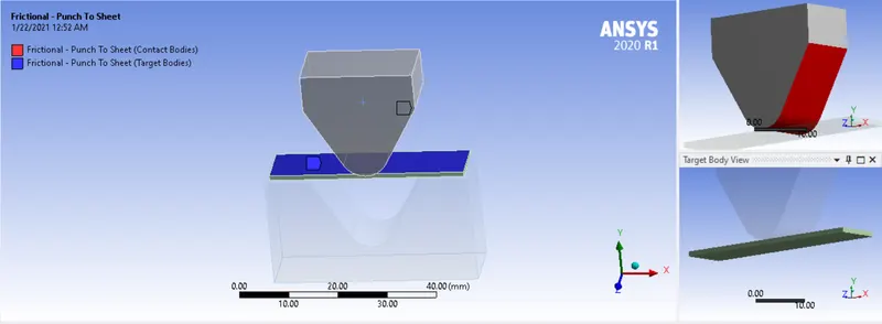
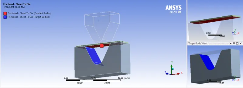
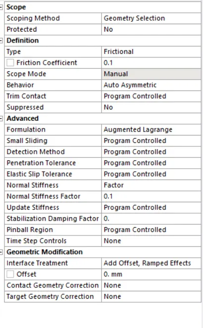
The automatic contacts are deleted and the contacts are given manually by selecting the contact and target bodies accordingly. The fictional coefficient is taken as 0.1.
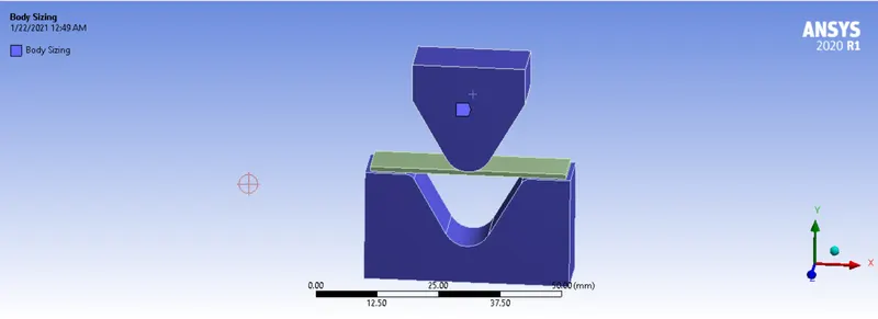
Mesh: For the die and punch by selecting body sizing, the mesh size is taken as 4mm, mesh size for sheet is taken as 1mm and for the area where there are contacts, the size is taken as 1mm. The element type for the sheet's mesh is taken as tetrahedron.
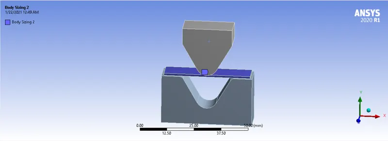
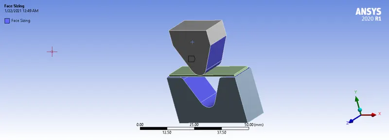
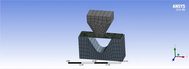
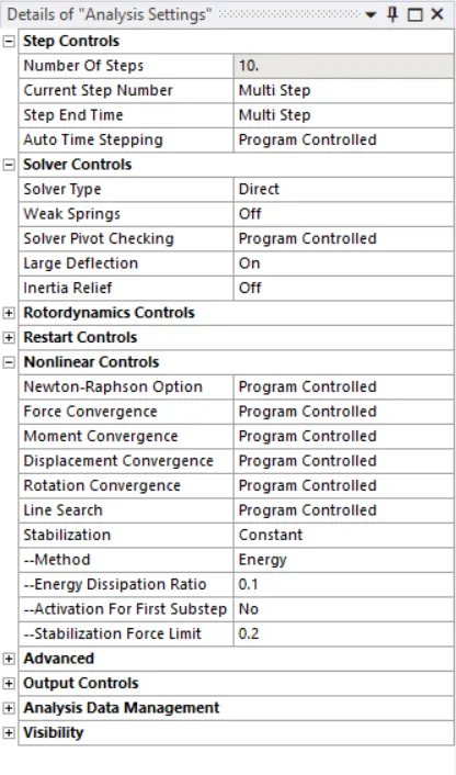
Boundary Conditions: The punch should displace in -y direction and should be constrained in other directions. The sheet should also be fixed in its postion only and the same goes with the die. 10 steps are taken and displacement is given to die.
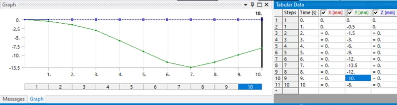
Analysis settings:
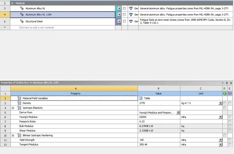
Case 1: Aluminium NL 1199
Properties
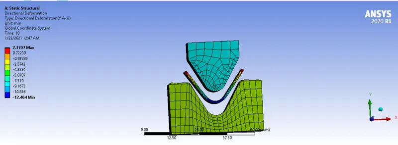
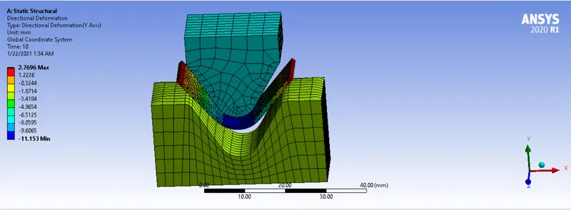
Total deformation (Y)
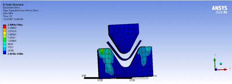
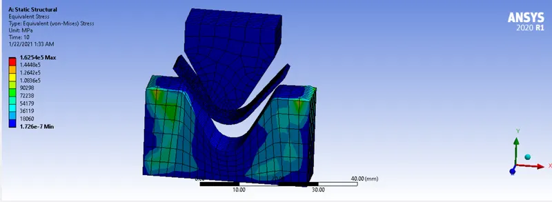
Equivalent stress
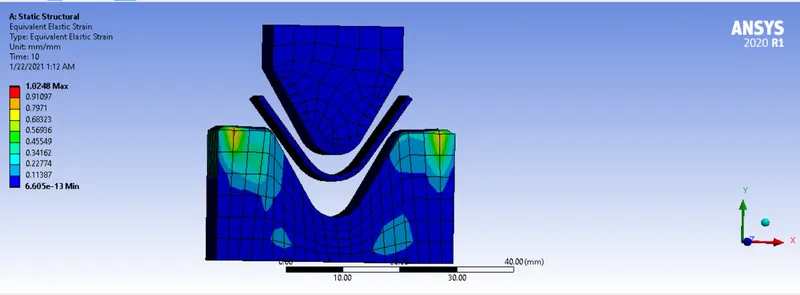
Equivalent strain
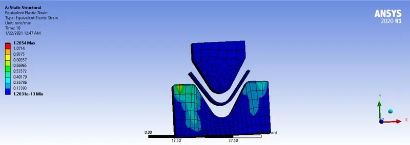
Copper alloy NL
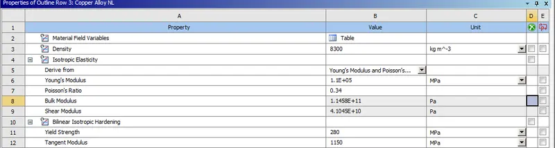
Properties
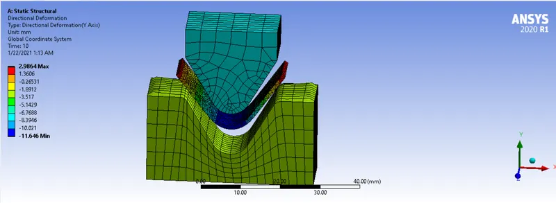
Total deformation (Y)
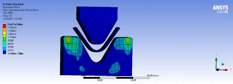
Equivalent stress
Equivalent strain
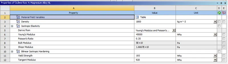
Magnesium alloy NL
Properties
Total deformation (Y)
Equivalent stress
Equivalent strain
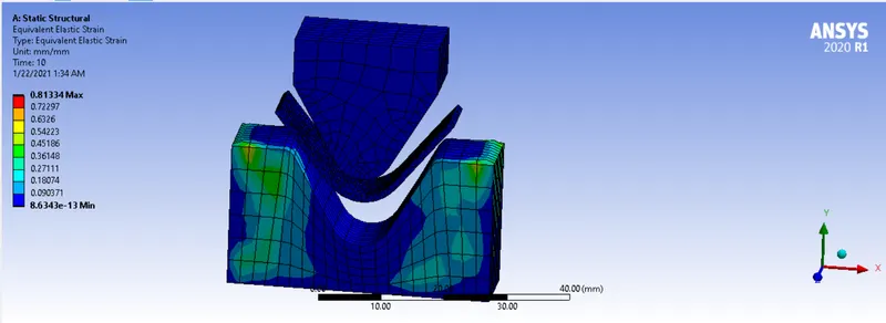
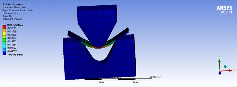
Case 2: Frictional coefficient 0.19
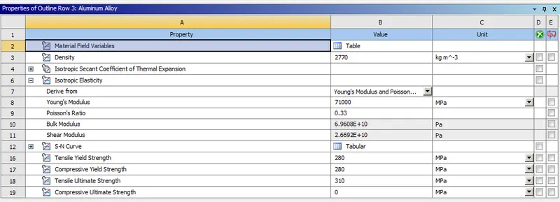
The following coefficient is taken and the analysis is performed with aluminium alloy as material
Properties
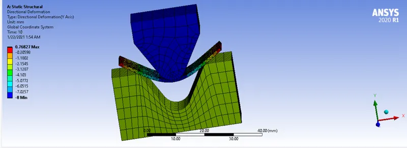
Total deformation (Y)
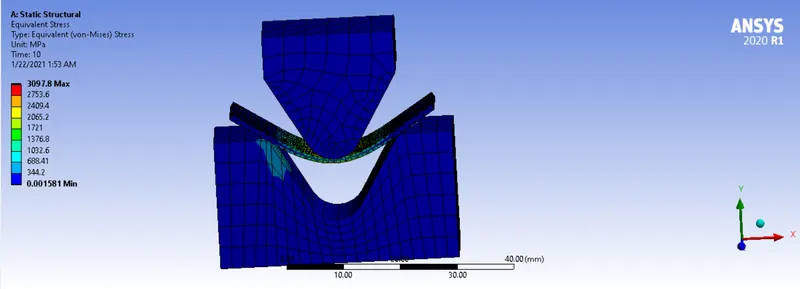
Equivalent stress
Equivalent strain
Case 3: Taking mesh size as 0.75mm for plate
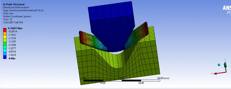
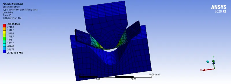
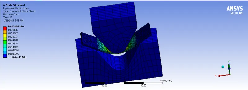
The mesh size for the plate is changed and taken as 0.75mm, we could go for even further lesser value but need to make changes in contact setings and load steps as it ccould not run the simulation with the existing settings. For this size, the time steps taken are increased to 15 so that no errors(convergence and element distortion) would occur while solving.
Total deformation (Y)
Equivalent stress
Equivalent strain
Results: The results are tabulated below for all the cases accordingly
Case 1
| Materials | Deformation Y direction (mm) | Equivalent stress (MPa) | Equivalent strain (mm/mm) |
| Aluminium alloy NL 1199 | 12.46 | 240000 | 1.2 |
| Copper alloy NL | 11.6 | 200000 | 1 |
| Magnesium alloy NL | 11.1 | 160000 | 0.8 |
Case 2:
| Materials | Deformation Y direction (mm) | Equivalent stress (MPa) | Equivalent strain (mm/mm) |
| Aluminium alloy | 8 | 3097 | 0.043 |
Case 3:
| Materials | Deformation Y direction (mm) | Equivalent stress (MPa) | Equivalent strain (mm/mm) |
| Aluminium alloy | 8 | 3084 | 0.043 |
Conclusion:
Case 1:
The maximum values for all the 3 solution parameters is observed when Aluminium alloy NL 1199 is used and the least values are identified for Magnesium alloy NL. So Magnesium alloy is preferable for sheet while undergone bending. Properties like Yield strength, Young's Modulus, Shear Modulus and Bulk Modulus all have their influence on the stresses and deformations of a particular component.
Case2:
When compared to results of case1, increasing frictional coefficient and changing the material to Aluminium alloy has given very least values which is highly suitable for our sheet
Case 3:
As the mesh size used was not significantly different than the one used for above cases, we could not see much of a difference, but with the decrease in mesh size, the accuracy of solution increases but one has to be careful with the errors which might occur if mesh size is changed.