Week 3 Sheet metal Bending challenge
AIM:
To simulate the sheet metal bending for their total deformation,stress and strain using ansys workbench.
SHEET METAL BENDING PROCESSES:
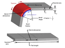
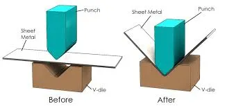
Sheet metal bending is a process by which metal can be deformed when applying force to the subject, which causes it to bend at an angle and form the anticipated shape, which often results in it being in a ‘V’ or a ‘U’ shape.
A press brake is a tool used in order to bend sheet metal and uses a punch and die to do this. Although press braking may seem straight forward, it can be quite difficult to remain accurate throughout the process. There are several types of press brakes which deliver different levels of force applied, such as mechanical, pneumatic, hydraulic and CNC to name a few examples.
Bending of sheet metal is a common and vital process in manufacturing industry. Sheet metal bending is the plastic deformation of the work over an axis, creating a change in the part's geometry. Similar to other metal forming processes, bending changes the shape of the work piece, while the volume of material will remain the same. In some cases bending may produce a small change in sheet thickness. For most operations, however, bending will produce essentially no change in the thickness of the sheet metal. In addition to creating a desired geometric form, bending is also used to impart strength and stiffness to sheet metal, to change a part's moment of inertia, for cosmetic appearance and to eliminate sharp edges.
OBJECTIVES:
csae: 1
In this proceses using three major materials, thats are
Aluminium Alloy 1199
Density = 2700 kg/m^3
Young's modulus = 62000 MPa
poisson ratio = 0.33
yield Strength = 140 MPa
Tangent Modulus = 209.46 MPa
Copper Alloy NL
Density = 8300 kg/m^3
Young's modulus = 1.1E+05
poisson ratio = 0.34
yield Strength = 280 MPa
Tangent Modulus = 209.46 MPa
Magnesium Alloy
Density = 1800 kg/m^3
Young's modulus = 45000 Mpa
poisson ratio = 0.35
yield Strength = 193 MPa
Tangent Modulus = 920 MPa
case : 2
With the material as Aluminium Alloy, change the friction coefficient to 0.19 and run the analysis as mentioned in Case 1. Compare the results with that in case 1.
Case : 3
Refine the mesh on the plate such that it doesn't cross the academic limit. With Aluminium alloy as material, run the analysis as in Case 1 and compare the results.
PROCEDURES:
- First drop the static structural from the tool box.
- Then assign the required material from the engineering data.
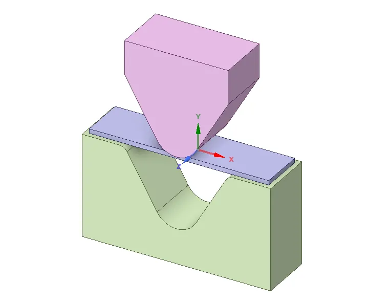
- A next one is the geometry, we can import the geomatry file, named as ''Skill_lync_Al_Sheet_Bending.x_t''
geometry
- Now open the model.
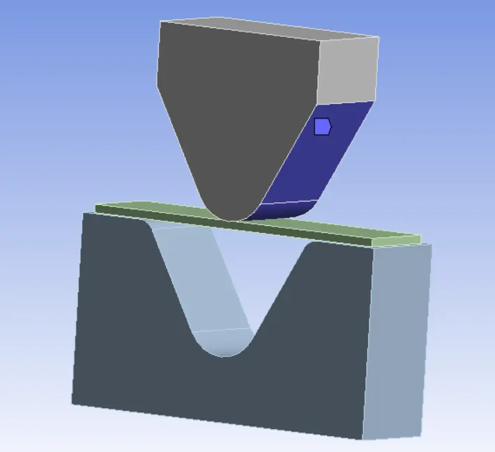
- Open a geometry, change the name as PUNCH,DIE,SHEET.
- First assign the required material for the components, like SHEET-ALUMINIUM ALLOY 1199.
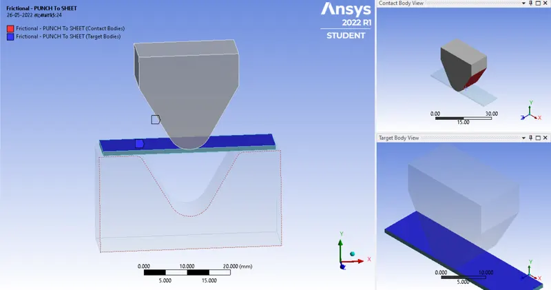
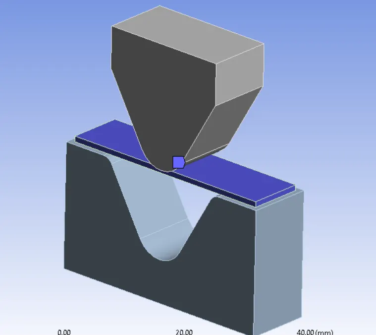
- Then delete a default connection, next insert the manual contact region.
Contact 1
contact body = punch
Target body = Sheet
Contact 2
contact body = Sheet
Target body = Die
CONTACT:1
CONTACT:2
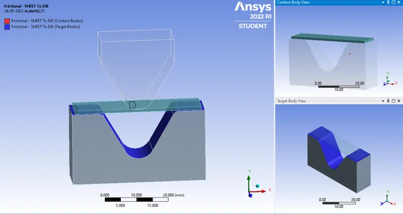
Type = Frictional
Frictional coefficient = 0.1
Behavior = Auto symetric
Formulation = Augmended legrange
Normal stiffness = Factor
Normal stiffness factor = 0.1
Interface Treatment = Add off set Ramped effects
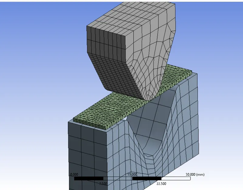
MESH :
- Now insert the sizing for the mesh
- Body Sizing = 4mm (For punch & Die)
- Body Sizing = 1mm (For Sheet)
- Body Sizing = 1mm (For All contact Faces)
- Then insert method
- Path conforming method = Tetrahedrons
Boundary conditions:
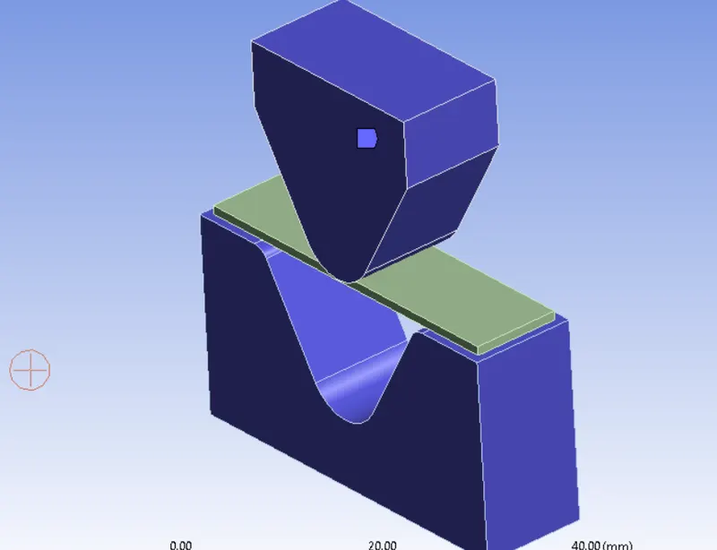
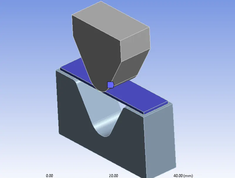
- After finishing mesh, open the analysis setting then creating boundary conditions
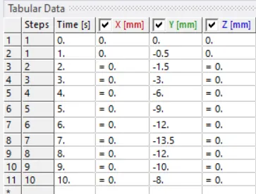
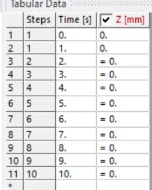
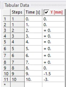
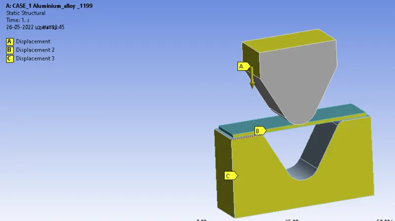
- Now insert a displacement
No of steps = 10
Large Deflection = ON
Stabilization = Contact
Energy Dissipation ratio = 0.1
Displacement=1 Displacement=2 Displacement=3
Solution:
- After giving proper boundary conditions,create desired solutions for output results,create solutions for Directional deformation, stress and strain. slove evaluate for solutions.
RESULTS:
case:1
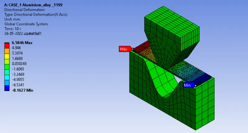
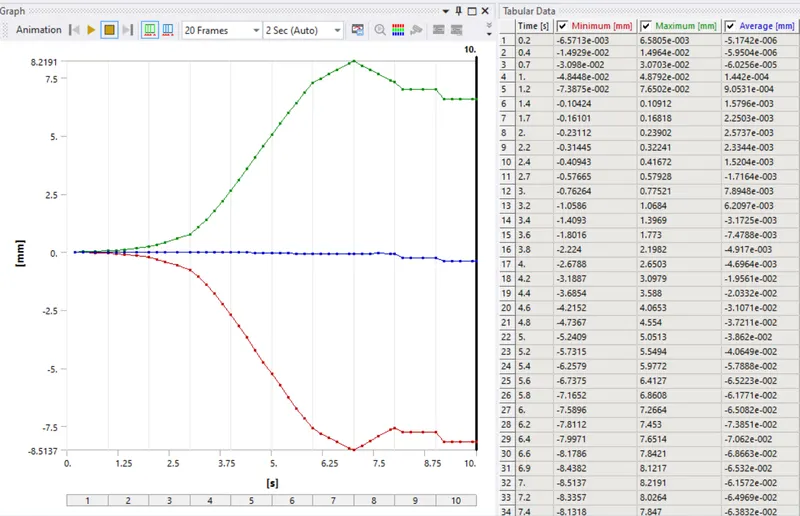
Directional deformation and graph for Aluminium Alloy 1199
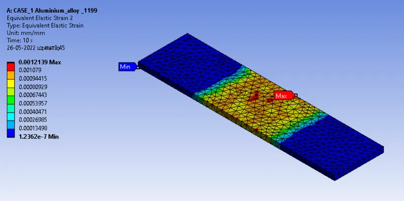
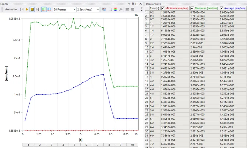
Equivalent strain and graph for Aluminium alloy 1199
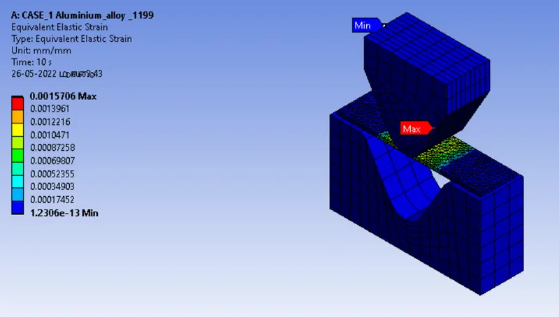
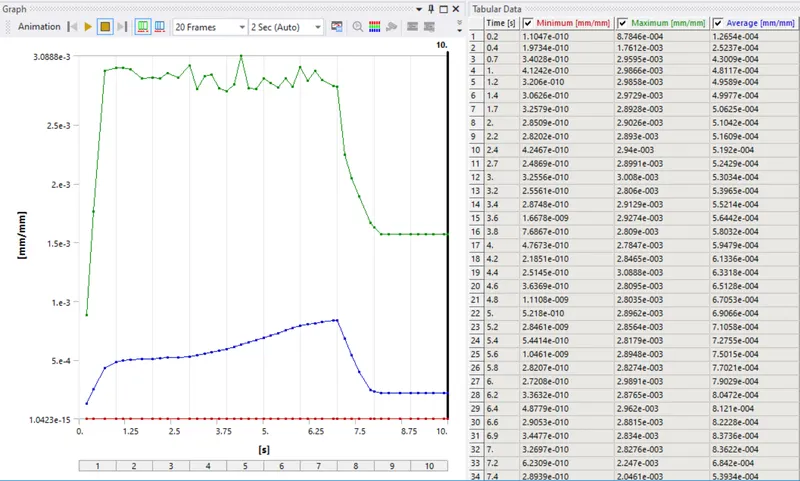
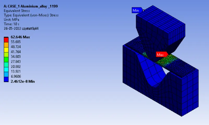
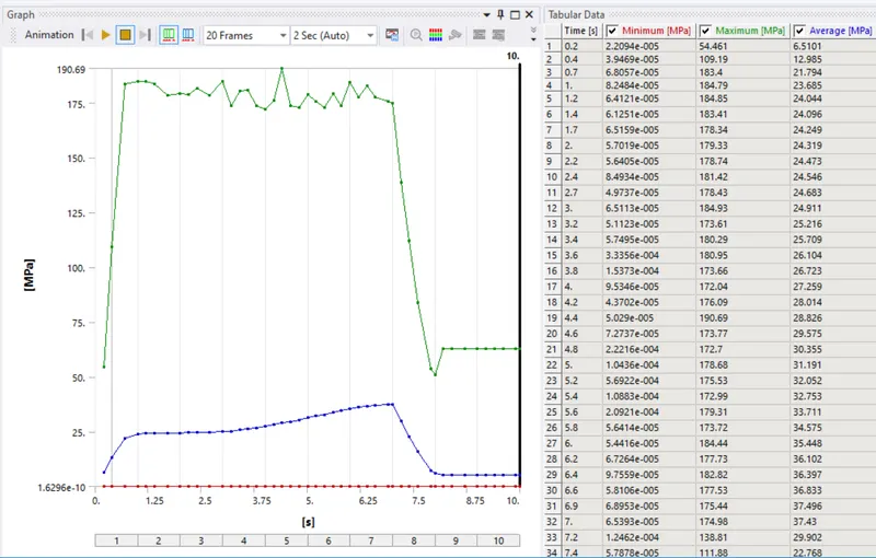
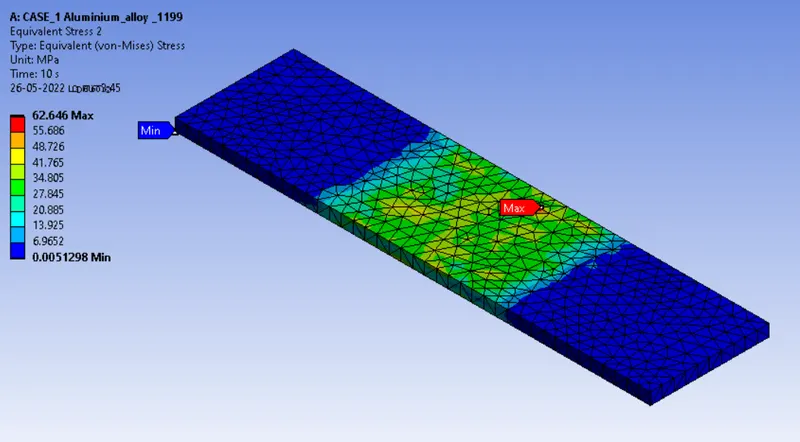
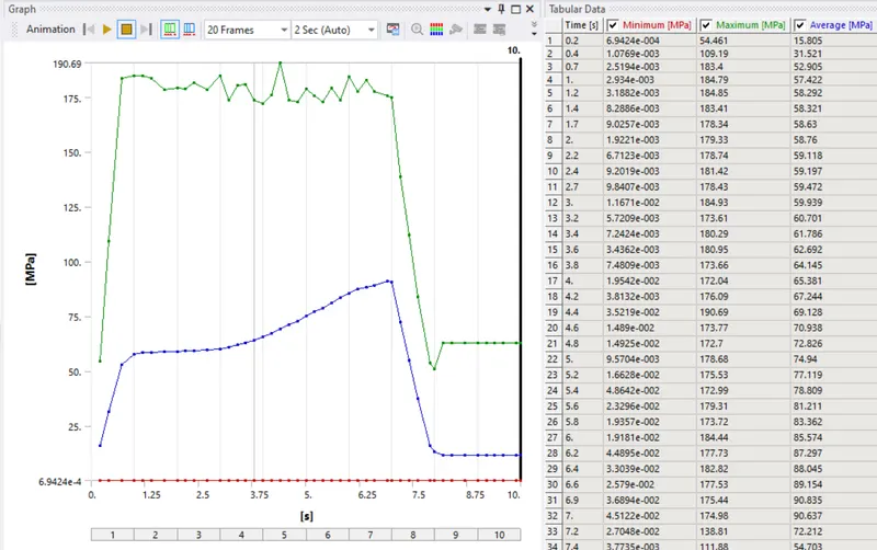
Equivalent stress and graph for Aluminium Alloy 1199
Equivalent strain and graph for Aluminium Alloy 1199
Equivalent stress and graph for Aluminium Alloy 1199
case : 2
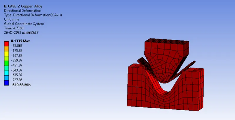
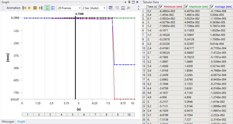
Directional derformation and graph for Copper Alloy NL
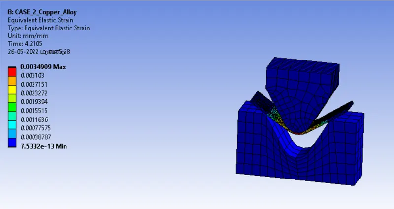
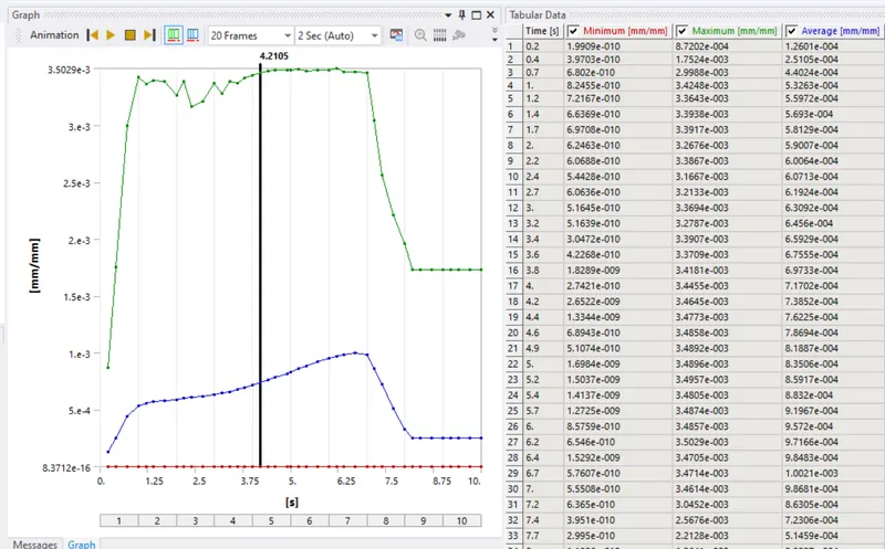
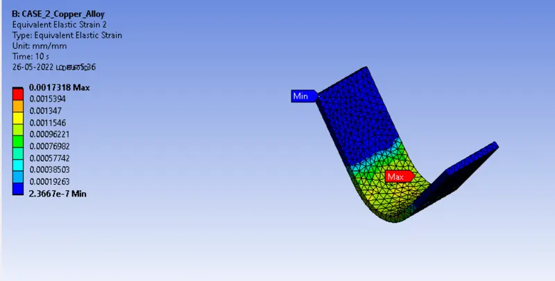
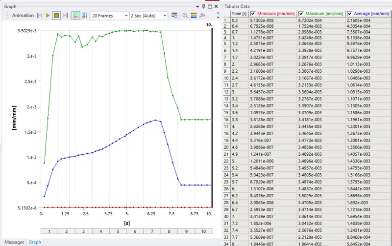
Equivalent strain and graph for Copper Alloy NL
Equivalent stress and graph for Copper Alloy NL
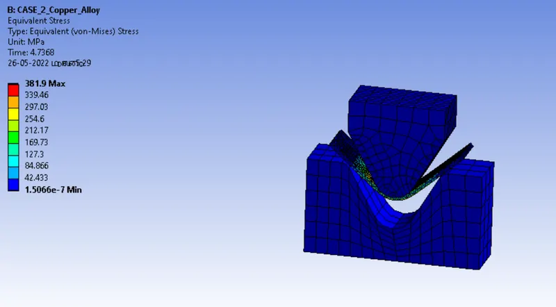
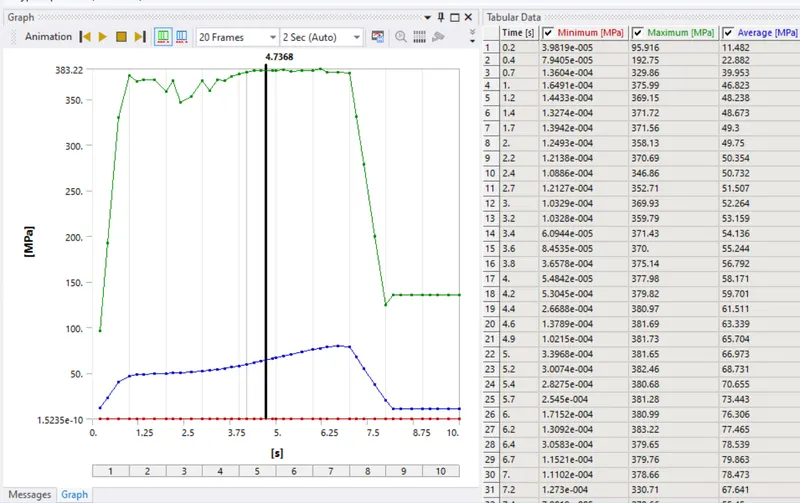
Equivalent strain and graph for Copper Alloy NL
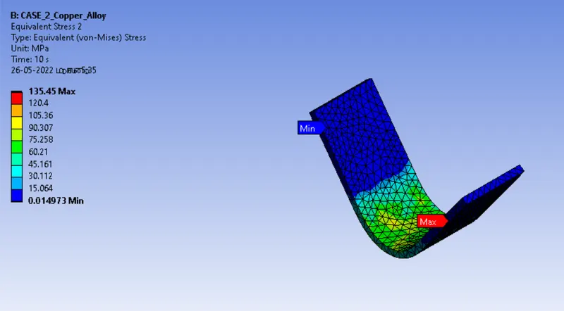
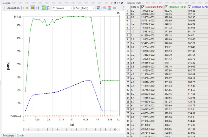
Equivalent stress and graph for Copper Alloy NL
case : 3
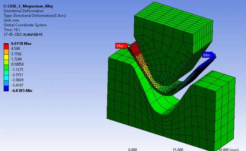
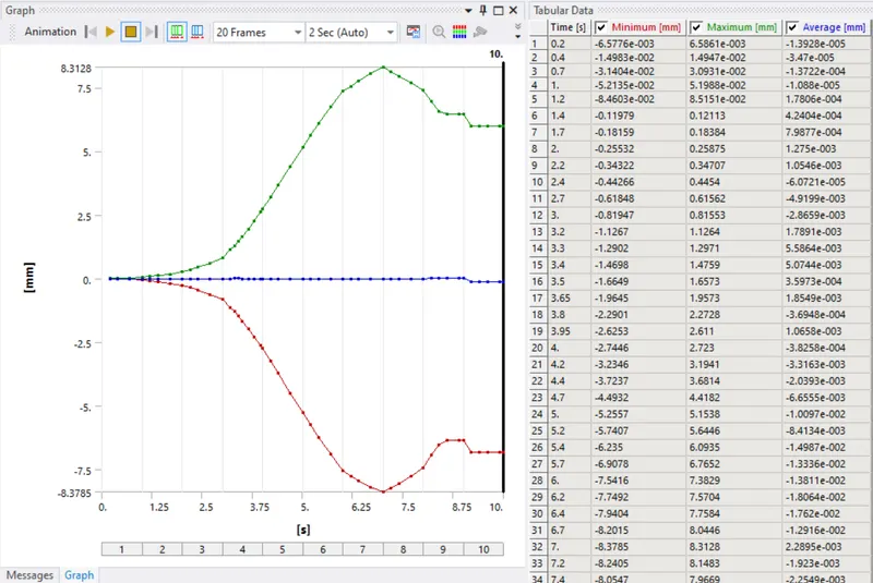
Directional derformation and graph for Magnesium Alloy NL
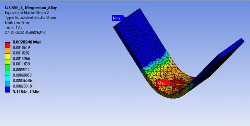
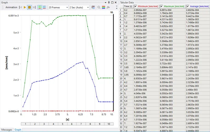
Equivalent strain and graph for Magnesium Alloy NL
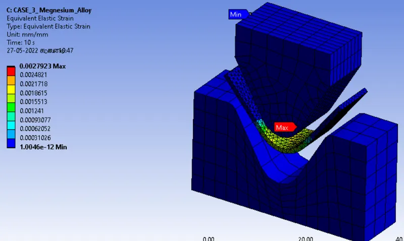
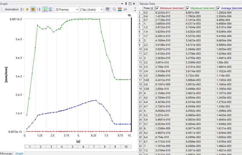
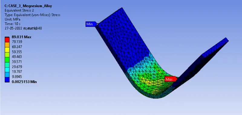
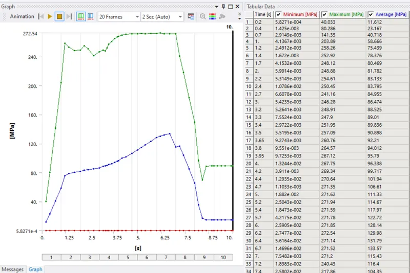
Equivalent stress and graph for Magnesium Alloy NL
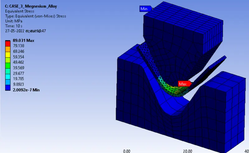
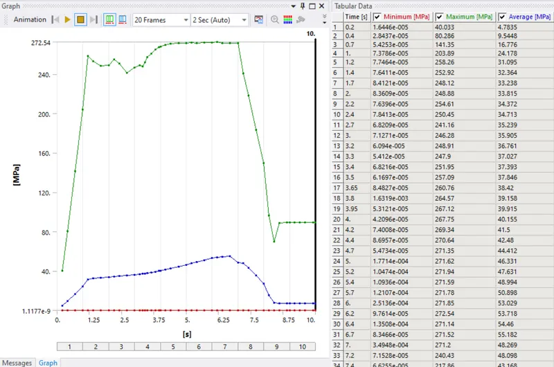
Equivalent strain and graph for Magnesium Alloy NL
Equivalent stress and graph for Magnesium Alloy NL
Comparession
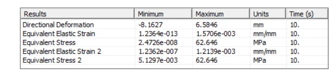
Al alloy 1199
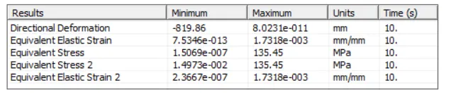
copper alloy
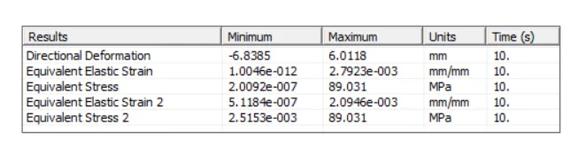
Magnesium Alloy
conclusion:
According to the above Result, a directioal deformation of copper alloy is higher then the aluminium alloy and magnesium alloy. In magnesium alloy, strain for sheet is more then the copper and magnesium alloy. Most of the result is lower then the magnesium alloy and aluminoium alloy. Due to the non linear material the stress in the sheet is lower compare to die.
case : 4
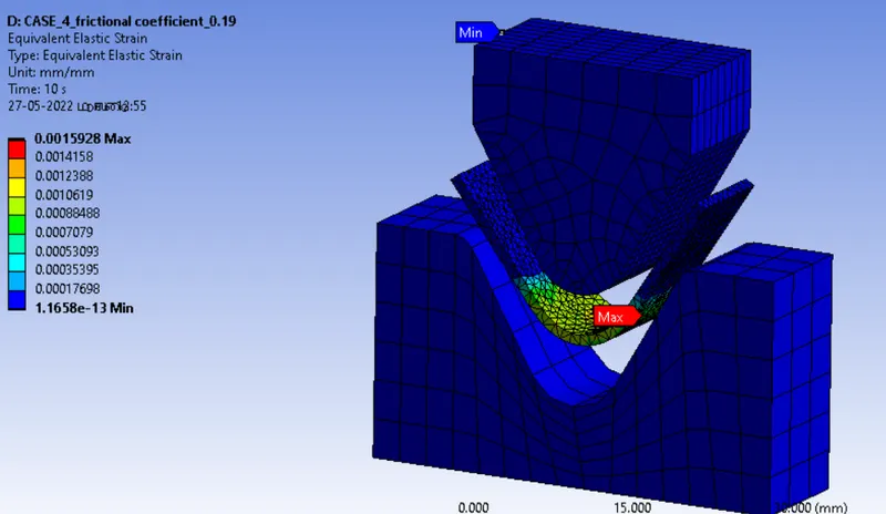
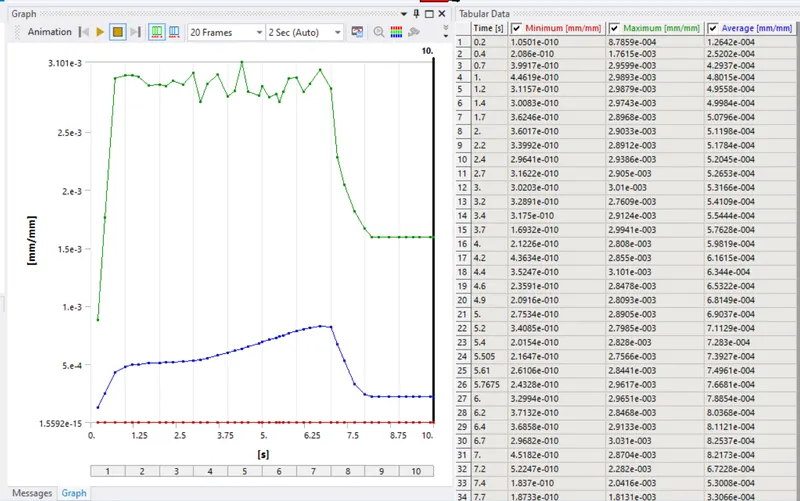
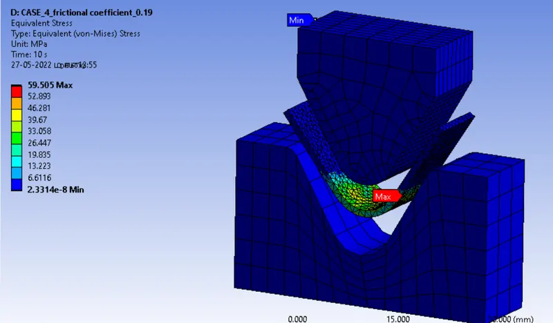
Change the friectionl coefficient to 0.19
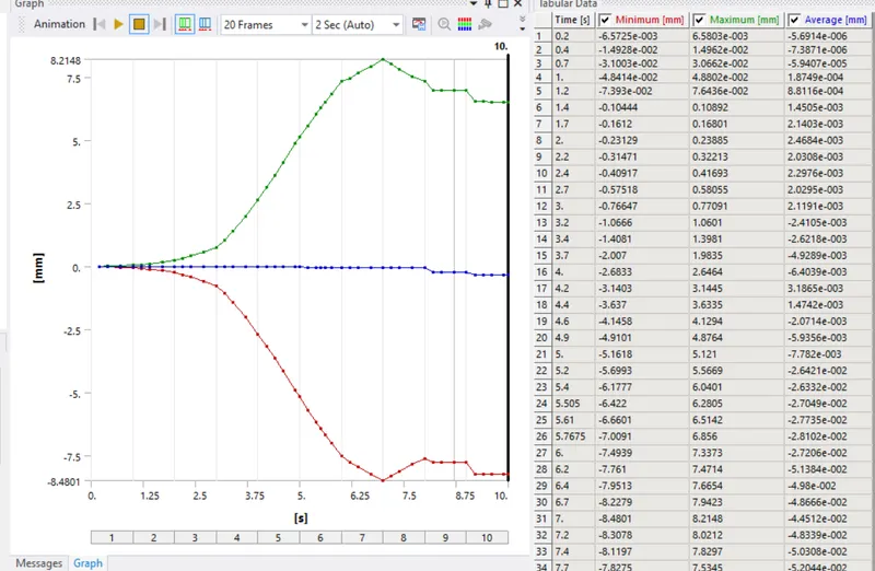
Directional derformation and graph for Aluminium Alloy 1199
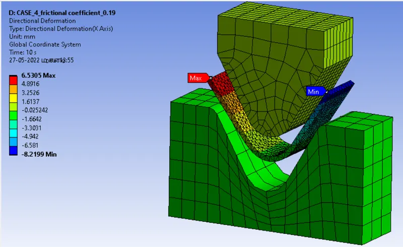
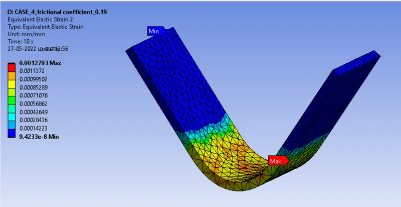
Equivalent strain and graph for Aluminium Alloy 1199
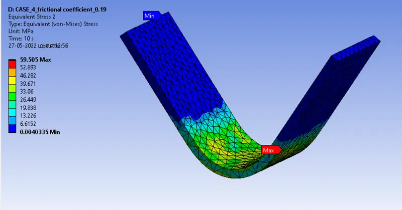
Equivalent stress and graph for Aluminium Alloy 1199
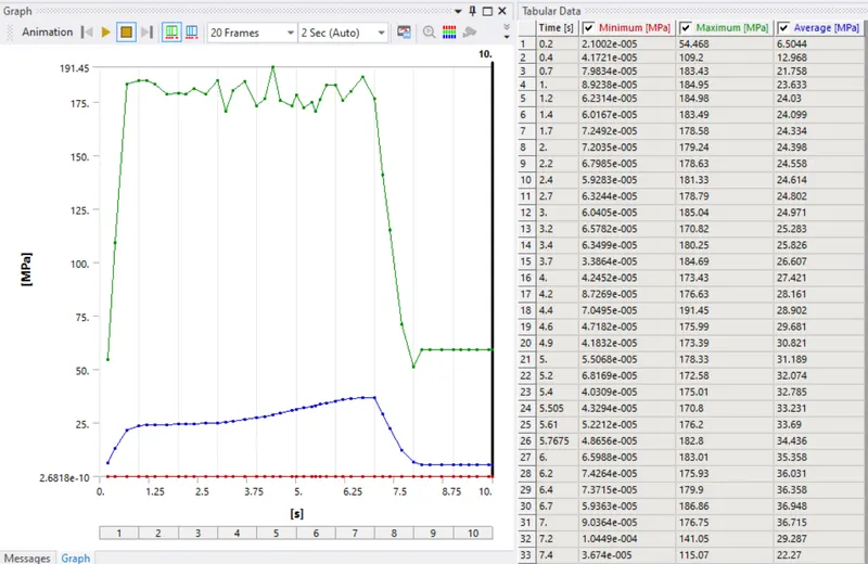
Equivalent strain and graph for Aluminium Alloy 1199
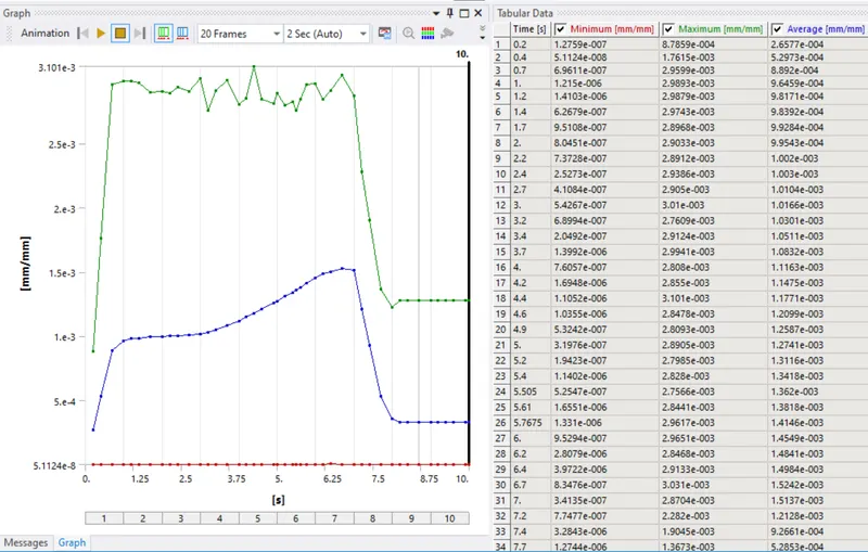
Equivalent stress and graph for Aluminium Alloy 1199
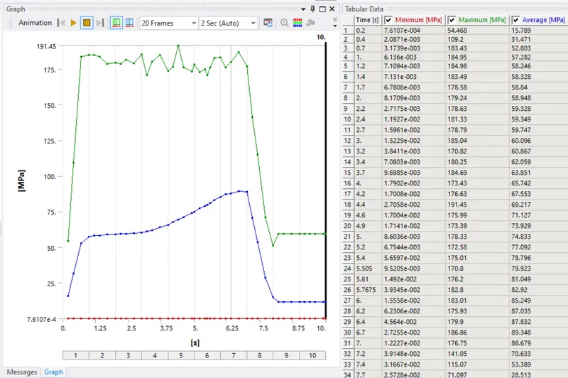
Comparession:
case 4
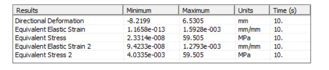
case 1
case :5
Refine the mesh value = 0.7
Directional derformation and graph for Aluminium Alloy 1199
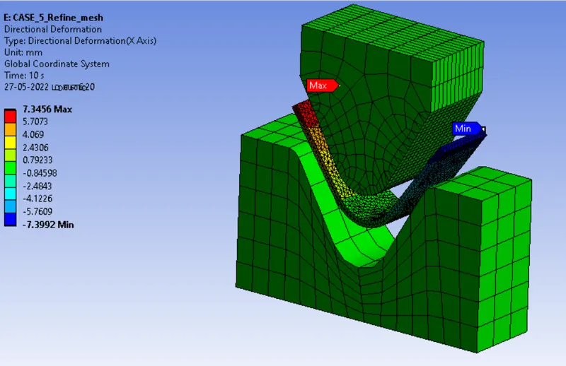
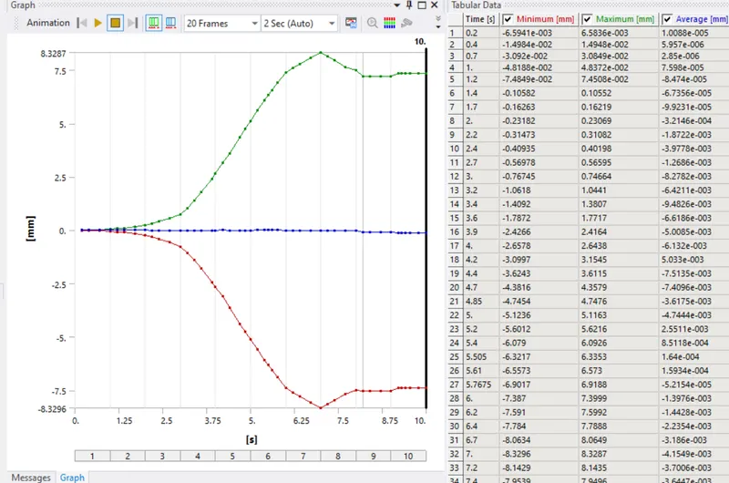
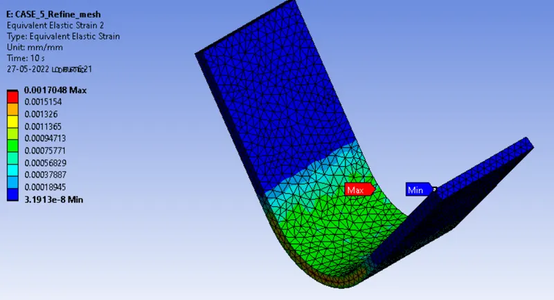
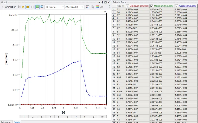
Equivalent strain and graph for Aluminium Alloy 1199
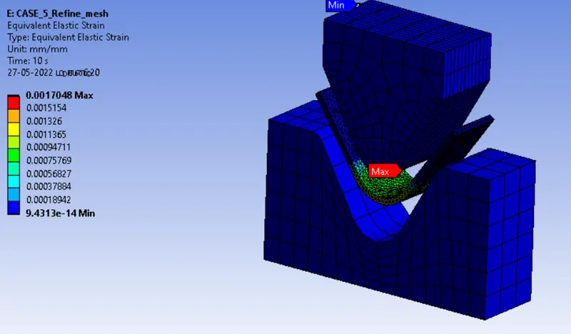
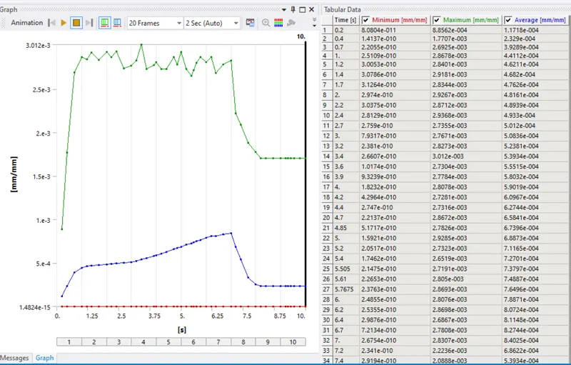
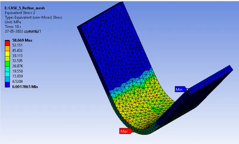
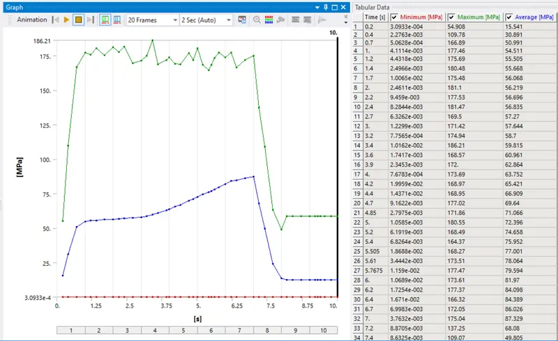
Equivalent stress and graph for Aluminium Alloy 1199
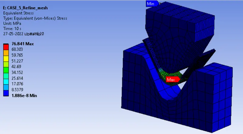
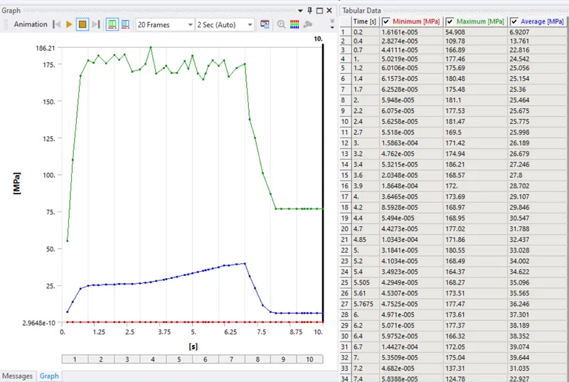
Equivalent strain and graph for Aluminium Alloy 1199
Equivalent stress and graph for Aluminium Alloy 1199
case 5
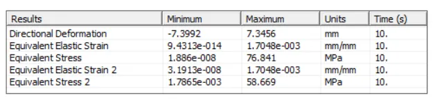
case 1