Week 3 Sheet metal Bending challenge
Sheet Metal Bending Challenge
OBJECTIVE:-
To perform a sheet metal bending simulation as per the cases given below and compared the output results for equivalent stress, equivalent elastic strain, and directional deformation.
Case 1
Modeling the sheet with Aluminium Alloy 1199, Copper Alloy NL, and Magnesium Alloy NL.
Case 2
With the material as Aluminium Alloy, change the friction coefficient to 0.19 and run the analysis as mentioned in Case 1. Compare the results with that in case 1.
Case 3
Refine the mesh on the plate such that it doesn't cross the academic limit. With Aluminium alloy as material, run the analysis as in Case 1 and compare the results.
INTRODUCTION:-
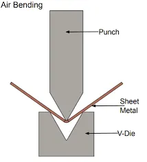
Sheet bending is a metal forming process in which a force is applied to a piece of sheet metal, causing it to bend at an angle and form the desired shape. A bending operation causes deformation along one axis, but a sequence of several different operations can be performed to create a complex part. Bent parts can be quite small, such as a bracket, or up to 20 feet in length, such as a large enclosure or chassis. A bend can be characterized by several different parameters.
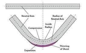
The act of bending results in both tension and compression in the sheet metal. The outside portion of the sheet will undergo tension and stretch to a greater length, while the inside portion experiences compression and shortens. The neutral axis is the boundary line inside the sheet metal, along which no tension or compression forces are present. As a result, the length of this axis remains constant.
PROCEDURE:-
Case 1
Modeling the sheet with Aluminium Alloy 1199, Copper Alloy NL, and Magnesium Alloy NL.
1) Open Ansys workbench and drop down the static structure onto the project window from the analysis systems.
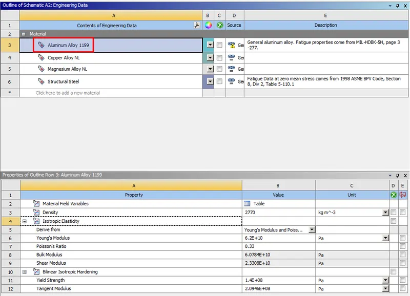
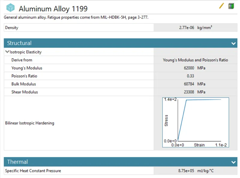
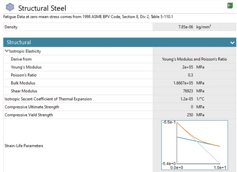
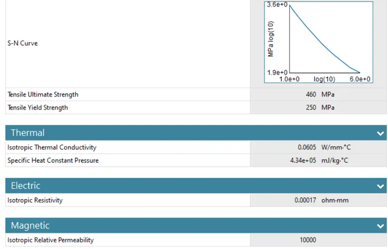
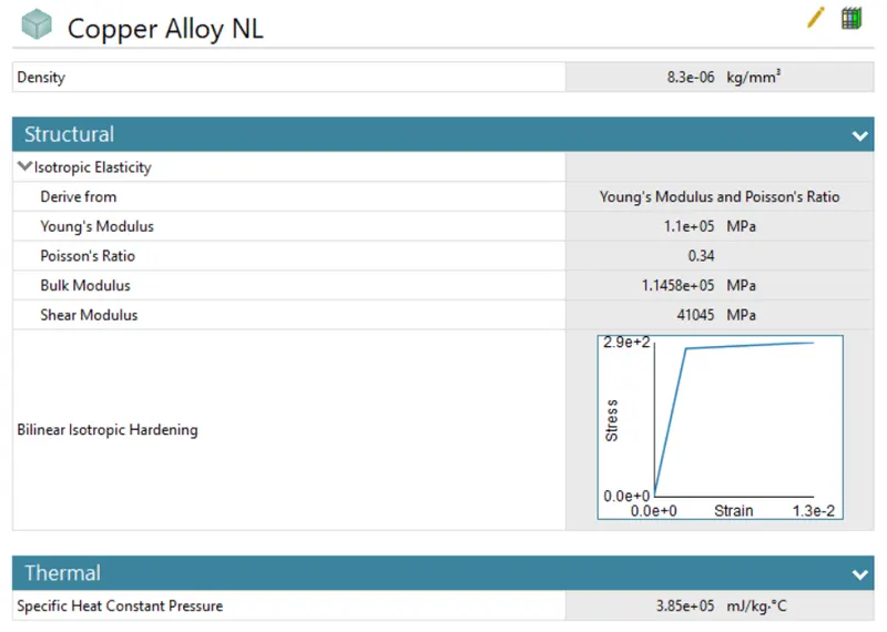
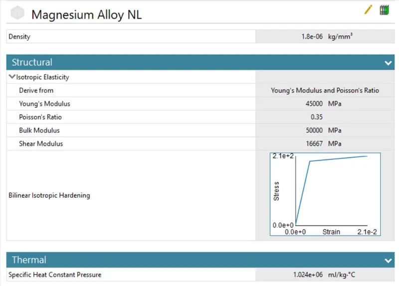
2) The material used for this project are Aluminium Alloy 1199, Copper Alloy NL, and Magnesium Alloy NL (General Non-linear materials) and its has been added from the engineering data. If any change is done to a material cad, check whether our unit systems are consistent.
3) Import the geometry and open it in the pace claim. The model was checked if any abnormality was present and the correction was made if needed. Click on the update and proceed to the next step.
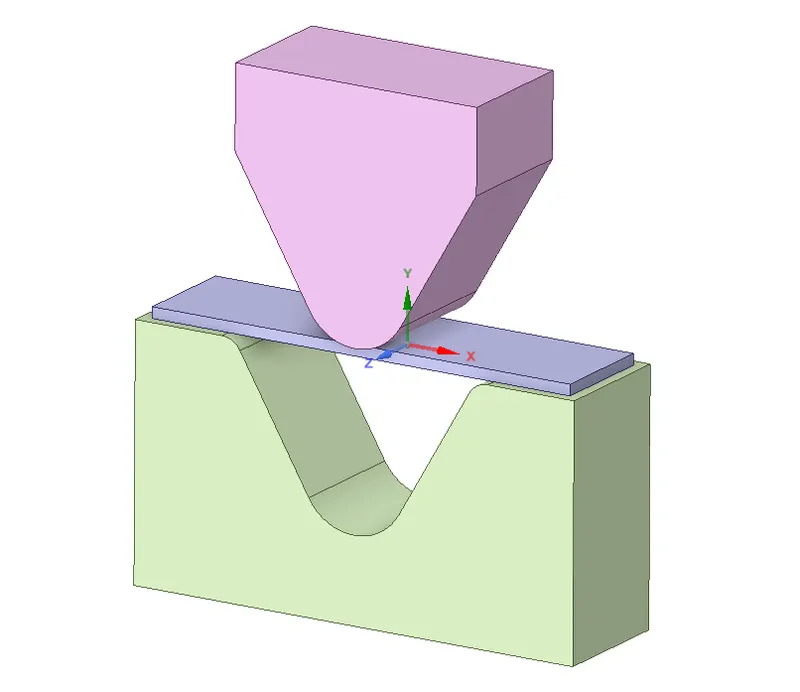
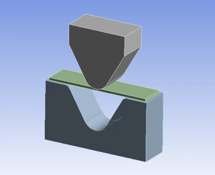
4) Right-click module and click edit to open up the mechanical module. The geometry tab is expanded and renamed accordingly.
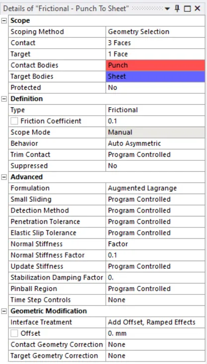
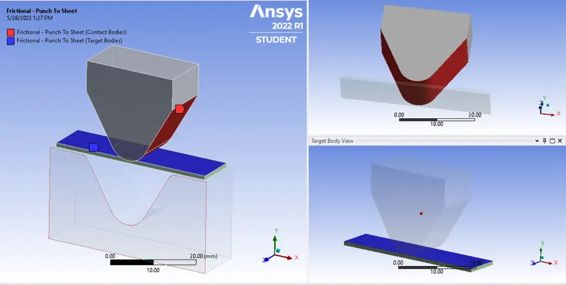
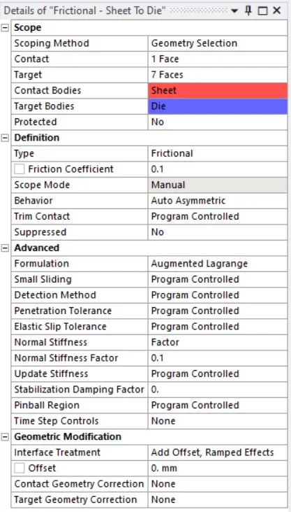
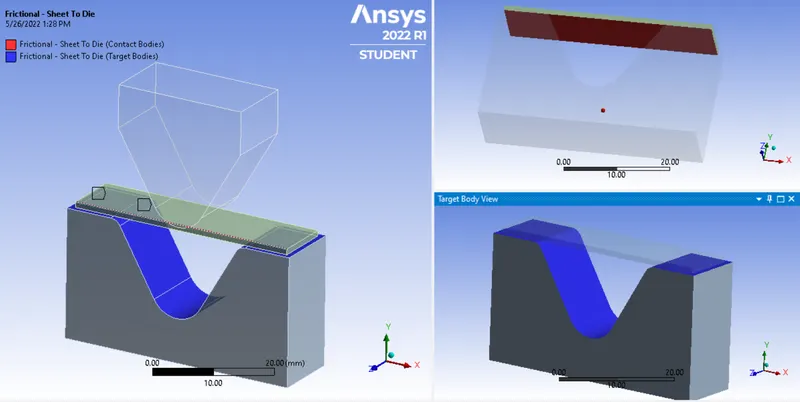
5) Expand the connection and from contact delete all the default contacts that have been generated. After that right-click contacts > insert > manual contact region. There will be contact between the punch and the sheet and selection were made. Select both the contact at once using control keys and change the type to frictional and assign a frictional coefficient of 0.1 with the behavior of Auto Asymmetric type. Other changes were made as shown below.
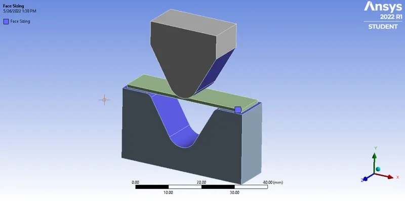
6) From the mesh, a mesh sizing was done for the die and the punch part using 4mm element size and an element size of 1mm for the sheet part. For the faces in contact, the mesh was refined by sizing to 1mm by selecting the corresponding faces as shown below.
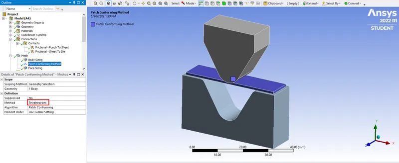
7) Before generating the mesh, right-click > insert > method, select the sheet and choose tetrahedron as the element type.
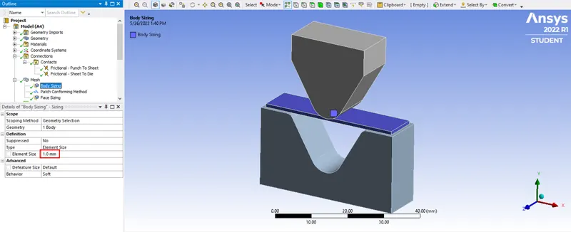
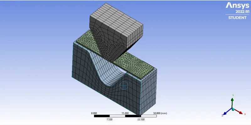
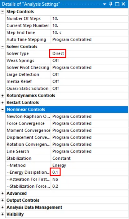
8) Now from the analysis set up, the total step was assigned as ten, and select all the time steps using the shift key and changes were done as per the image shown below.
9) Now the loads can be defined. During the bending process, the punch will advance downward and hits the sheet and after that, it will impact the die, it needs to be removed and the punch should move backward after the bending process is complete.
Static structural > insert > displacement, and select the three faces shown below. Also change the x,y,z components to tabular data.
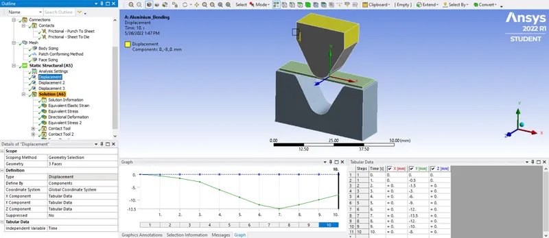
From the plot, it can be observed that the plot is moving forward up to a maximum displacement of 13.5mm, and then it's withdrawn back.
10) Now displacement for the sheet is defined. The motion in z-direction was fixed and after motion along x and y direction since sheet metal deform while bending. To fix the sheet in z-direction , right-click static structural > insert > displacement. Select the two faces shown below.
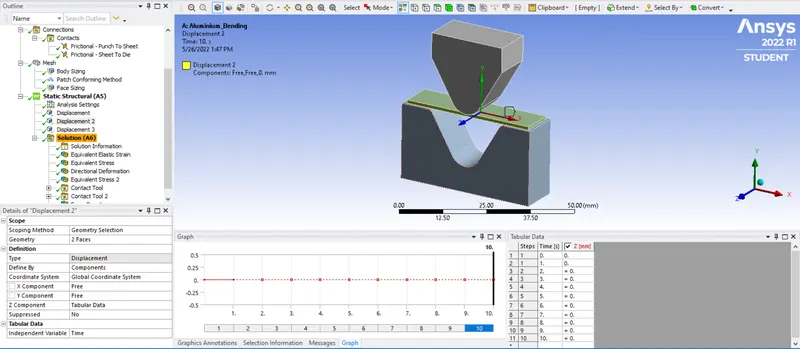
From definition>z-component>tabular data. With this, the movement will be constrained along the z direction.
11) For the die, select the five faces as shown below > right-click static structural > insert > displacement.
Here the all x,y, and z components are inserted from the tabular data. Since it needs to stay at this place until the punch advances and once the punch is withdrawn this die should be also withdrawn. So we change the last step as shown below.
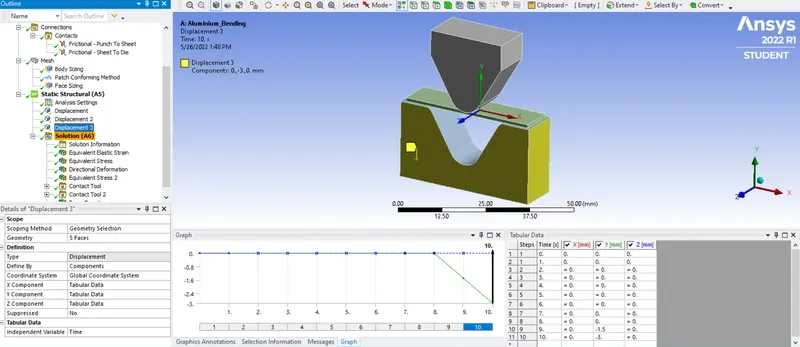
The data has been inserted along the y-direction and made sure that the die stays in place and after the punch is withdrawn, the die is also withdrawn with a 3mm displacement.
12) Finally, the output parameters such as the Equivalent stress, Equivalent elastic strain, and Total Deformation in the Y direction have been requested and run the simulation.
NOTE:- Same procedure is adopted for simulation setup and run for other 2 materials.
RESULTS:-
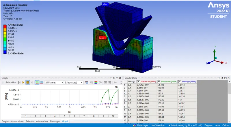
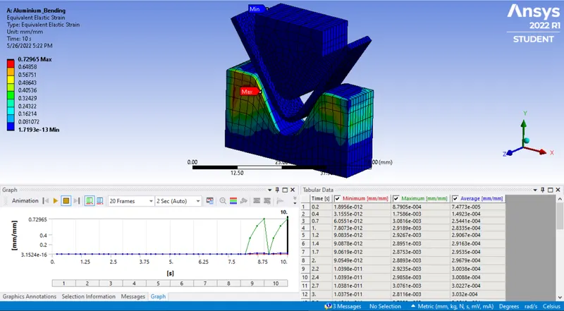
The simulation for sheet metal bending has been performed using three different materials and compared the results. The results got from the simulation are discussed below.
Aluminium Alloy 1199 -
Equivalent stress
Equivalent elastic strain
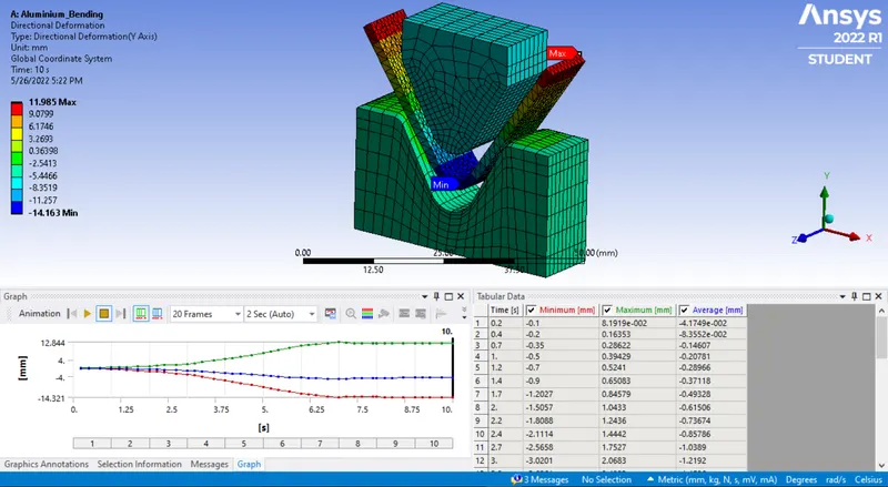
Directional deformation along Y-axis
Copper Alloy NL -
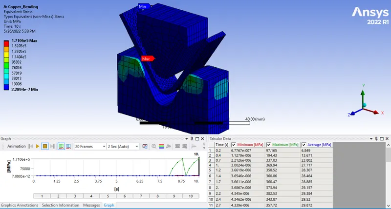
Equivalent stress
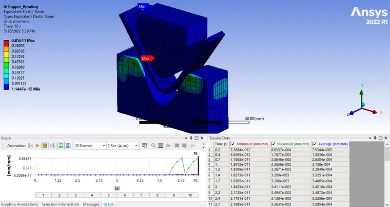
Equivalent elastic strain
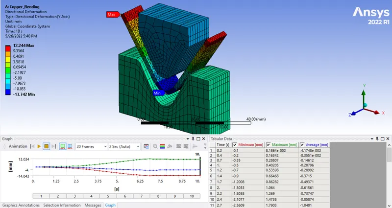
Directional deformation along Y-axis
Magnesium Alloy NL -
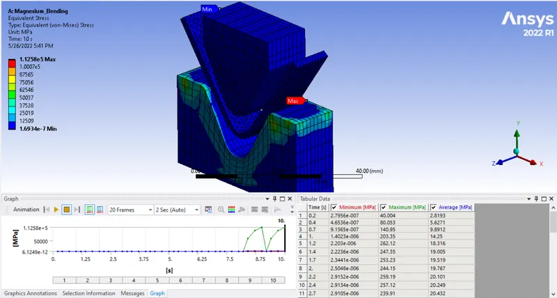
Equivalent stress
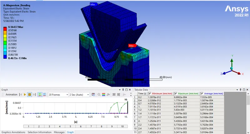
Equivalent elastic strain
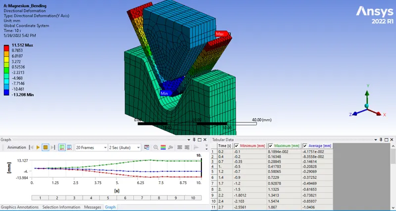
Directional deformation along Y-axis
COMPARISION:-
| Material | Coefficient of Friction | Max. Equivalent stress | Max. Equivalent elastic strain | Max. Directional Deformation(in Y-dir) |
| Aluminium Alloy 1199 | 0.10 | 1.4587E+05Mpa | 0.72965 | 11.985mm |
| Copper Alloy NL | 0.10 | 1.7106E+05Mpa | 0.85611 | 12.244mm |
| Magnesium Alloy NL | 0.10 | 1.1258E+05Mpa | 0.56437 | 11.512mm |
From the table, it's been observed that the sheet modeled with Copper Alloy NL gave the highest value for the equivalent stress and the Magnesium Alloy NL gave the minimum stress value. Therefore the sheet with Aluminum Alloy 1199 will be having maximum strength to withstand the failure compared to others in the list.
The equivalent strain was found to be more for Copper Alloy NL and least for Magnesium Alloy NL.
The directional deformation along Y-direction is highest for Copper Alloy NL and least for Magnesium Alloy NL and the sheet with Copper Alloy NL will bend more.
Case 2
With the material as Aluminium Alloy, change the friction coefficient to 0.19 and run the analysis as mentioned in Case 1. Compare the results with that in case 1.
For case 2 the Coefficient of friction was compared for the values for 0.1 and 0.19 using the Aluminum Alloy 1199 sheet material.
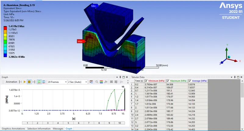
Aluminium Alloy 1199(Friction Coefficient=0.19)
Equivalent stress
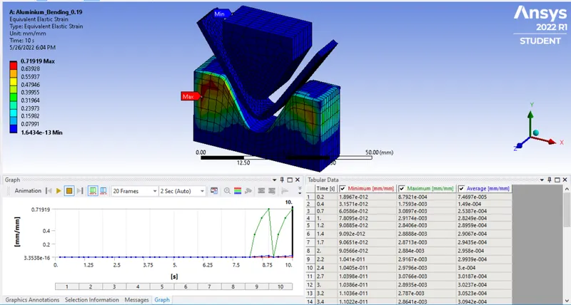
Equivalent elastic strain
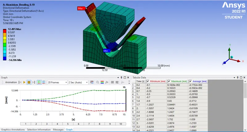
Directional deformation along Y-axis
COMPARISION:-
| Material | Coefficient of Friction | Max. Equivalent stress | Max. Equivalent elastic strain | Max. Directional Deformation(in Y-dir) |
| Aluminium Alloy 1199 | 0.10 | 1.4587E+05Mpa | 0.72965 | 11.985mm |
| Aluminium Alloy 1199(Friction Coefficient=0.19) | 0.19 |
1.43785E+05Mpa |
0.71919 |
12.495mm |
The maximum equivalent stress with a coefficient of 0.19 is less compared to 0.1. So when the frictional coefficient is increased the equivalent stress value also decreases.
The equivalent elastic strain is more for co-efficient with 0.1.
The directional deformation with 0.19 is found to be the highest.
Case 3
Refine the mesh on the plate such that it doesn't cross the academic limit. With Aluminium alloy as material, run the analysis as in Case 1 and compare the results.
For case 3 simulation was performed by decreasing the mesh size for the sheet modeled with Aluminium Alloy 1199 sheet material with a frictional coefficient of 0.1.
Aluminium Alloy 1199(Refined)
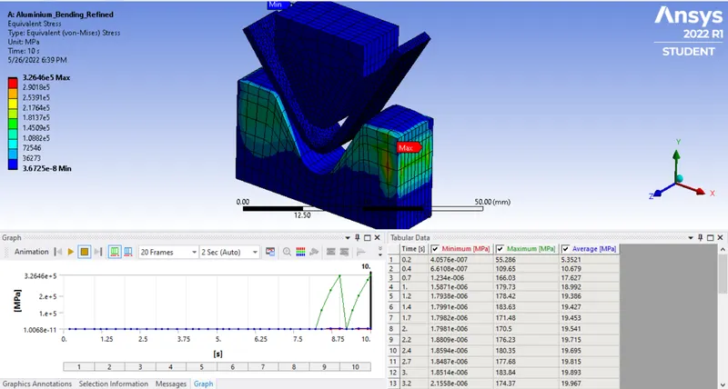
Equivalent stress
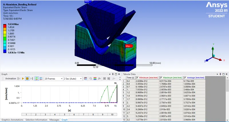
Equivalent elastic strain
Directional deformation along Y-axis
COMPARISION:-
| Material | Coefficient of Friction | Mesh Body Sizing | Max. Equivalent stress | Max. Equivalent elastic strain | Max. Directional Deformation(in Y-dir) |
| Aluminium Alloy 1199 | 0.10 | 1mm | 1.4587E+05Mpa | 0.72965 | 11.985mm |
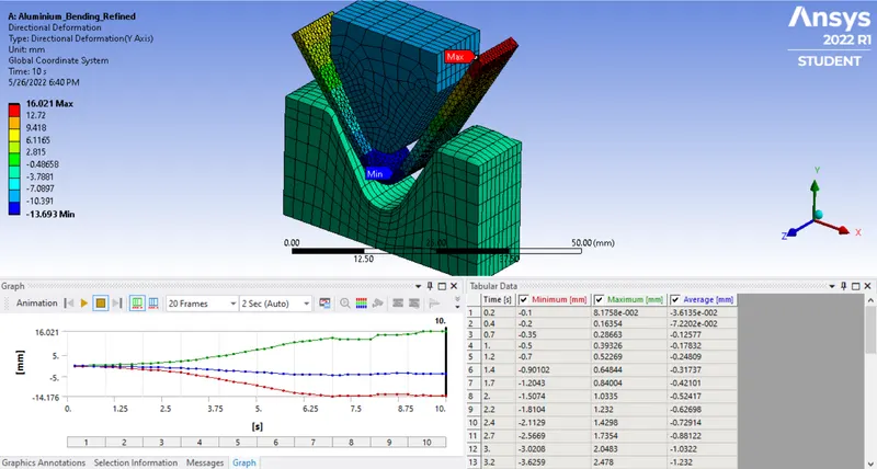
| Aluminium Alloy 1199(Refined) | 0.10 | 0.75mm | 3.2646E+05Mpa | 1.634 | 16.021mm |
From the table, it's observed that when the mesh size changes the value for the stress and strain changes. Here we can find that equivalent stress, equivalent elastic strain and Directional Deformation(in Y-dir) is more for 0.75mm mesh size.
Meshing is one of the key components to obtaining accurate results from an FEA model. Typically, the smaller the mesh size, the more accurate the solution as the designs are better sampled across the physical domains. The trade-off is that the higher the accuracy, the larger the simulations become, and thus solving time is extended. There is no point in spending extra hours running a simulation with a dense mesh If a coarser mesh will give you the results you need. Engineers often perform convergence studies to obtain the optimal balance between accuracy and solve time.