Week- 5 - Solid meshing
Solid meshing
AIM:
For the given Rear view mirror component, check for the geometrical errors and mesh the Surfaces with the given 2D element Quality criterias given below.
|
S.No |
Quality Criteria |
Value |
|
1 |
Target/Average length |
1 |
|
2 |
Minimum Length |
0.5 |
|
3 |
Maximum Length |
2 |
To use tetra elements to mesh the Volumes defined in the model and check for the below quality after Volume meshing.
|
S.No |
Quality Criteria |
Value |
|
1 |
Tet collapse |
0.2 |
PREPROCESSOR USED: ANSA Preprocessor
PROCEDURE:
Solid meshing or volume meshing is a 3D meshing type in which mesh is generated throughout the whole volume of the model rather than just generating it on the model's surface which is exactly what is done in 2D meshing. Solid mashing covers the entire volume of the model with 3D elements connected with the help of hot points, usually Tetra elements which is an unstructured mesh type because elements are randomly connected with each other without following any specific structure in unstructured meshing whereas Hexa meshing is a type of structured meshing.
- Surface meshing or 2D meshing is used to be done on components having thickness less than 5 mm.
- Solid meshing is preferred for components having thickness greater than 5 mm.
Procedure adopted for solid meshing somewhat differs as compared to 2D meshing which can be explained with the help of following steps.
- Importing the CAD model
- Topology or Geometry cleanup
- Quality criteria setup for shell/surface meshing
- Surface meshing
- Quality criteria setup for solid/volume meshing
- Volume defining and Property ID setup
- Solid meshing
- Releasing the elements from the CAD
1. Importing the CAD Model:
Following commands can be used for importing CAD file of the model.
ANSA.File>Open>File Name
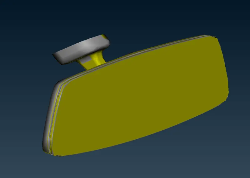
Fig: CAD Model
2. Topology or Geometry Cleanup:
Geometry checks are performed on the model using checks manager to ensure if the CAD model is proper and it is not having any defects and errors. If errors occur then they are eliminated whether using Autofix or by fixing them manually but before that topo is performed and length between hot points is adjusted to 1 to get a proper view of the model.
Tools>Checks>Geometry>All entities>Execute
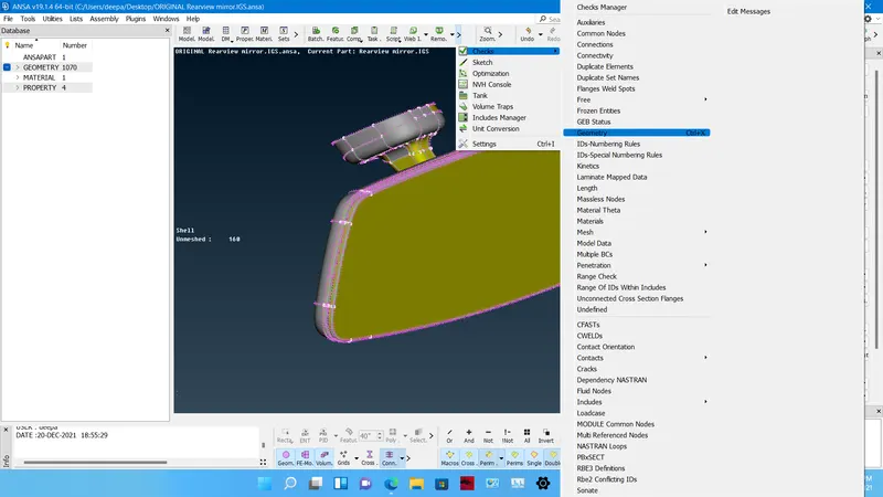
Fig: Checks Manager
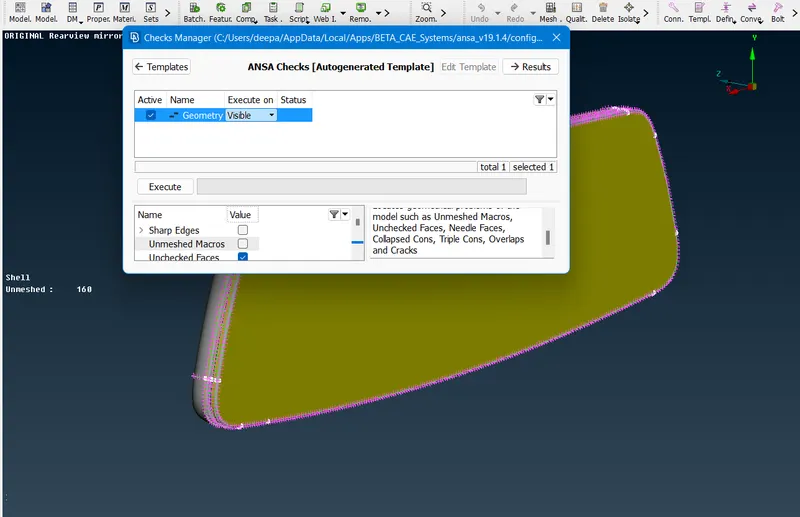
Fig: Geometry Checks
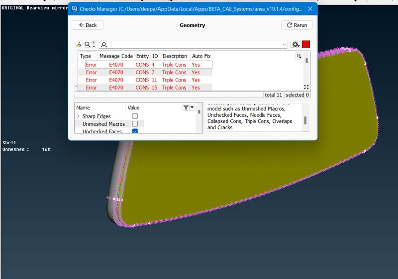
Fig: Before Applying Fix
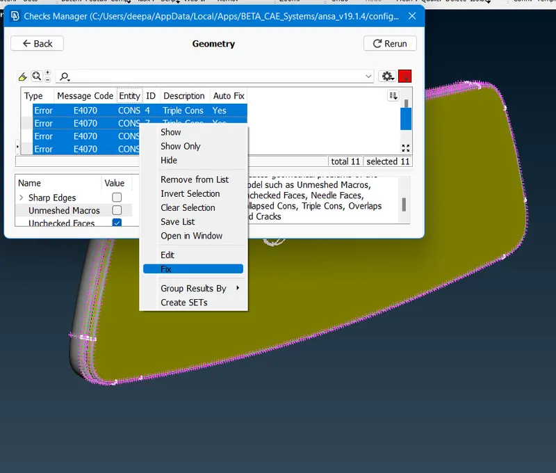
Fig: Applying Autofix
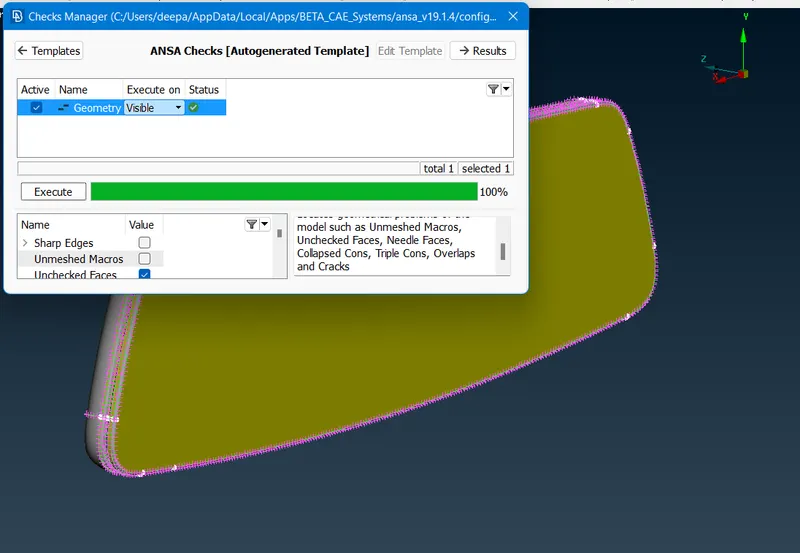
Fig: After Applying Fix
After performing the fixes, measurements are taken at various places of the model having features like fillets to ensure that elements would not fail for minimum length quality criteria at those places and unnecessary cuts are removed while new cuts and faces are introduced if required.
3. Quality Criteria Setup for Shell/Surface Meshing:
Hot points are set up according to target or average length decided and Quality criteria is set up for shell meshing or 2D meshing after geometry cleanup of the model as per given quality criteria. Element type is changed to Ortho Tria from mixed element type.
Utilities>Mesh Parameters
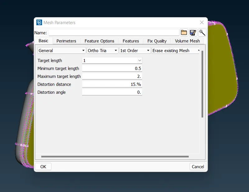
Fig: Mesh Parameters
Utilities>Quality Criteria
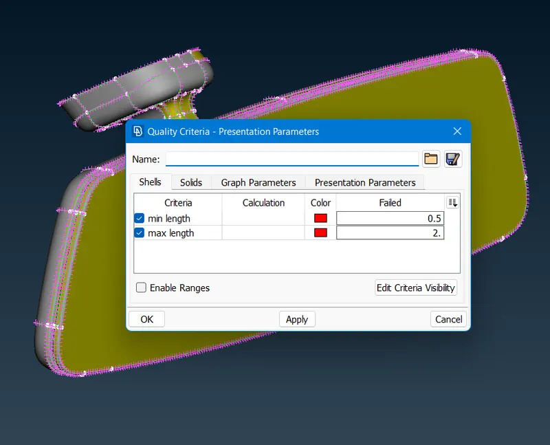
Fig: Shell Mesh Quality Criteria
4. Surface Meshing:
Now the model surface is meshed starting from fillet regions and curvy areas which are meshed with ortho tria element type using spot mesh option and then remaining flat regions of the model is meshed with tria elements using spot mesh option.
Mesh>Mesh Generation>Spot Mesh
- Reconstruct option can be used to alter the mesh flow.
Mesh>Shell Mesh>Reconstruct
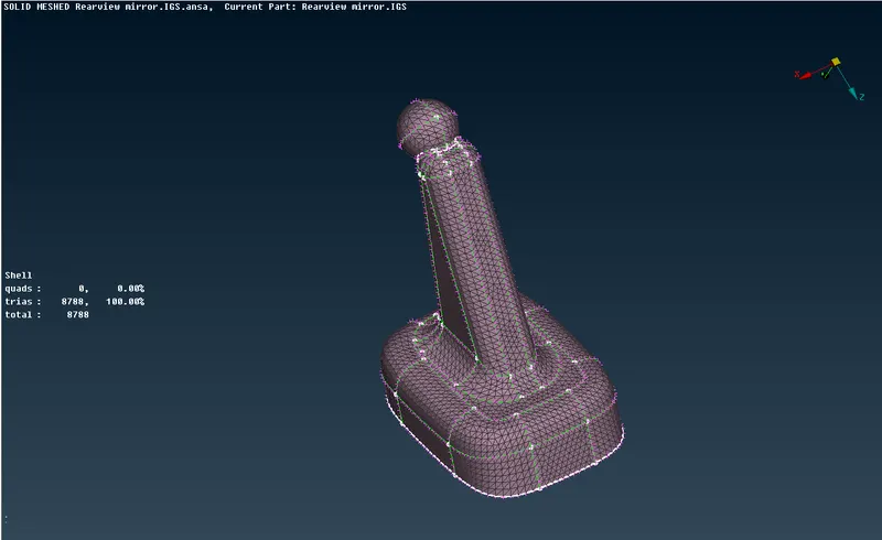
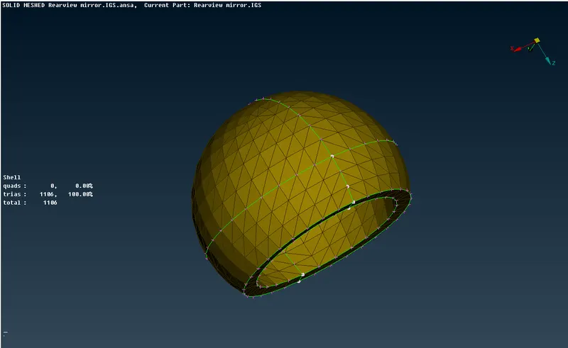
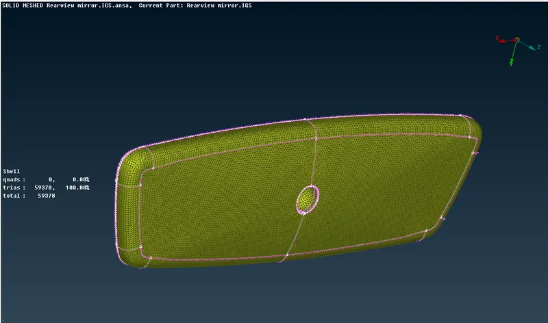
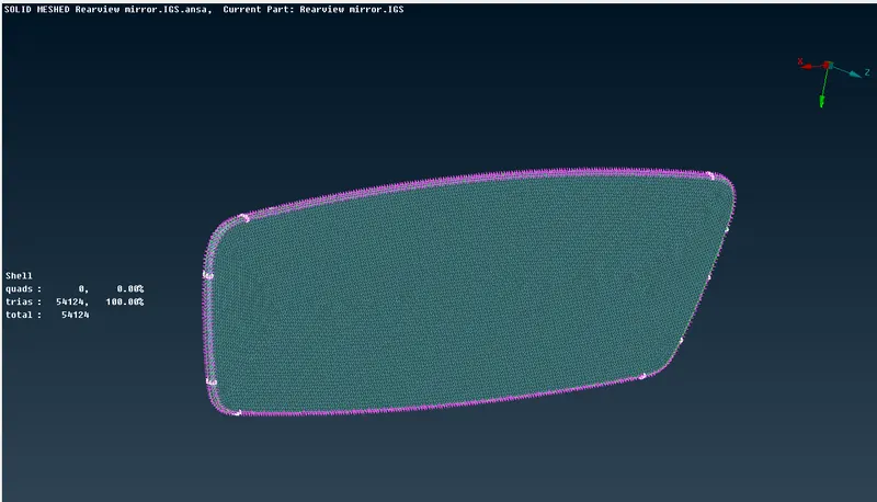
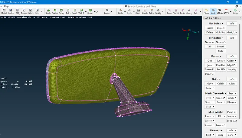
Fig: Shell Meshed Rear view Mirror
5. Quality Criteria Setup for Solid/Volume Meshing:
Quality criteria is set up for solid meshing once after shell meshing is done. only one quality criteria is defined for solid meshing in this model which is called Tet Collapse having max allowable limit of 0.2.
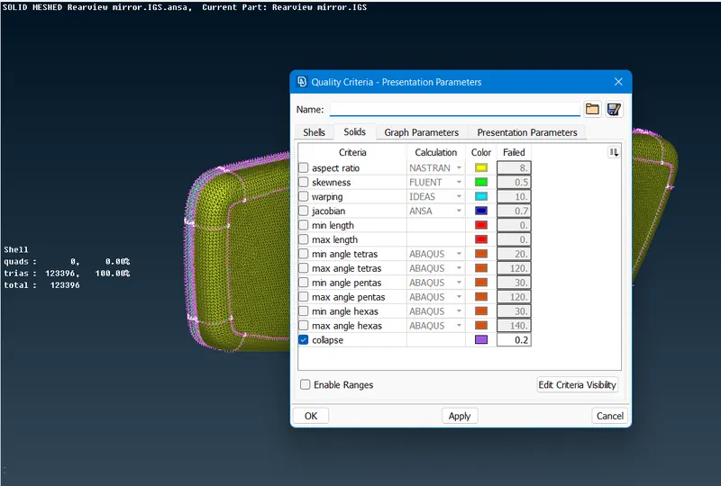
Fig: Volume Mesh Quality Criteria
6. Volume Defining and Property ID setup:
Before starting with volume meshing, defining the volume to be meshed is important so that ANSA can detect the component as a closed volume. Property ID setup is done after defining volume.
- For defining the volume, following procedure is adopted.
Volume Mesh>Volumes>Define>Manual>Select the component with box selection>Middle mouse click to confirm
- For Setting up the Property ID for volume defined, following procedure is adopted.
Volume Mesh>Volumes>List>New>PSOLID>Edit the PID name>Ok>Select the PID>Double left mouse click
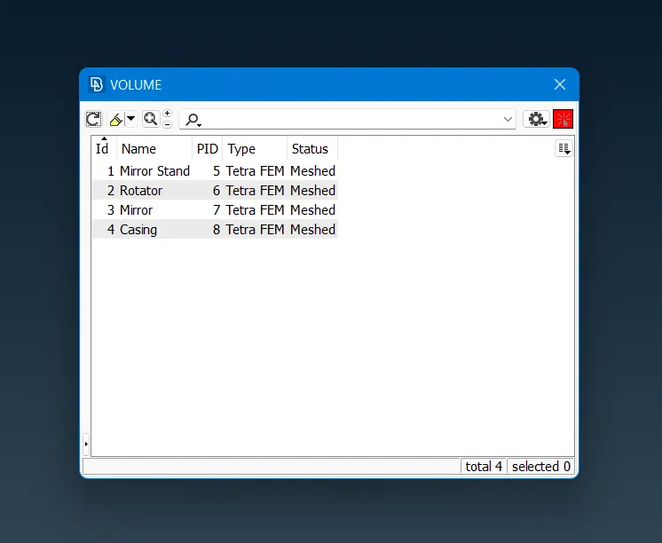
Fig: Property IDs Setup
7. Solid Meshing:
Solid Meshing can be performed with some of the meshing algorithms available in ANSA like Tetra Rapid, Tetra FEM etc. but here, Tetra FEM is used.
- For Tetra FEM-
Volume Mesh>Unstructured Mesh>Tetra FEM
- For Tetra Rapid-
Volume Mesh>Unstructured Mesh>Tetra Rapid
- After the volume meshing quality of the tet collapse failed elements is to be fixed by adjusting the position of the nodes of the failing element while moving the nodes in x,y or z directions. Similarly all other quality issues can be cleared.
Mesh>Grids>MV Free>Select the node and move
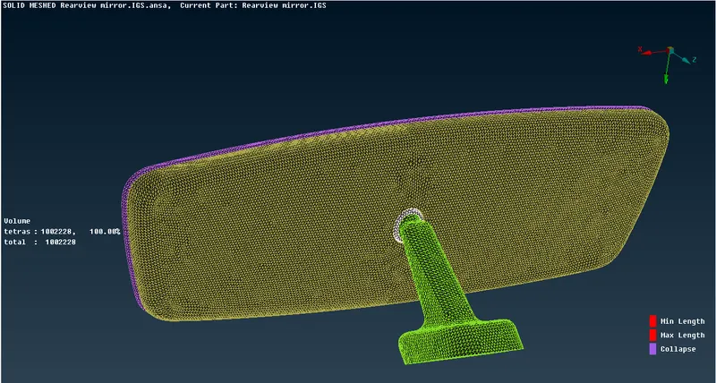
Fig: Solid Meshed Rear view Mirror
8. Releasing Elements from the CAD:
The final step of solid meshing is to release the meshed elements from the CAD and following process can be followed for the same.
Volume Mesh>Volumes>Release>Box select the component>middle mouse click to confirm
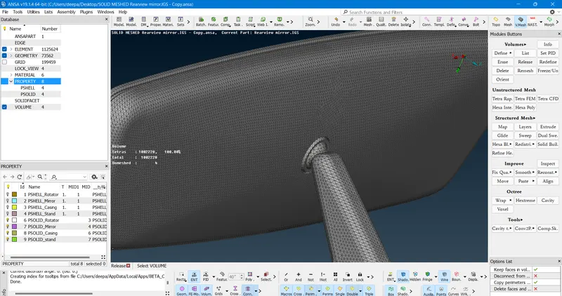
Fig: FE Model of Rear view Mirror
CONCLUSION:
Successfully worked on Rear view mirror model and generated solid mesh of the same under given quality criteria.
LEARNING OUTCOMES:
- Got Aware of shell meshing using tria and ortho tria element types.
- Learned about unstructured tetra meshing.
- Learned to setup quality criteria for solid meshing.
- Worked with V.Mesh Module and solid meshing.
- Learned to use Tetra FEM and Tetra Rapid meshing algorithms.