Week - 4 - 2D meshing for Plastic components
2D meshing for Plastic components
AIM:
For the given Plastic Bottle Cap model, check for the geometrical errors and take the mid surface by suitable mid surfacing techniques. PID and Thickness assignment has to be done for all the mid surfaces. Mesh the same with given element Quality criteria. (Refer the table Below for the Quality criteria)
|
S.No |
Quality Criteria |
Value |
|
1 |
Target/Average length |
1 |
|
2 |
Minimum Length |
0.5 |
|
3 |
Maximum Length |
3 |
|
4 |
Aspect |
3 |
|
5 |
Warpage |
15 |
|
6 |
Skewness |
45 |
|
7 |
Jacobian |
0.7 |
|
8 |
Minimum Quad Angle |
45 |
|
9 |
Maximum Quad Angle |
135 |
|
10 |
Minimum Tria Angle |
30 |
|
11 |
Maximum Tria Angle |
120 |
|
10 |
Tria Percentage |
15 |
PROCEDURE:
Preprocessing of the Plastic Bottle Cap model includes various steps like Geometry cleanup, Mid surface extraction, Meshing etc. which are mentioned below.
1.Importing CAD file
2.Model geometry checks
3.Thickness measurement
4.Mid surface generation
5.Thickness and Property ID assigning
6.Setting up hot points and quality criteria
7.Meshing
Let us discuss the steps mentioned above one by one.
1.Importing CAD File:
Following commands can be used for importing CAD file of the model.
ANSA.File>Open>File Name
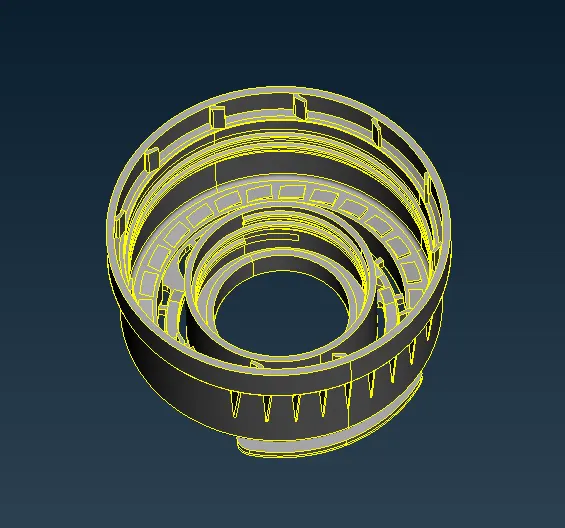
Fig:CAD File
2.Model Geometry Checks:
After importing the model in graphical display, measurements are taken on various regions of the model. If thickness of component is varying then it confirms that the component is made up of plastic and after that, geometry checks are performed on the CAD model. Geometry of features and surfaces should be proper which is checked using Checks Manager.
Tools>Checks>Geometry>All entities>Execute
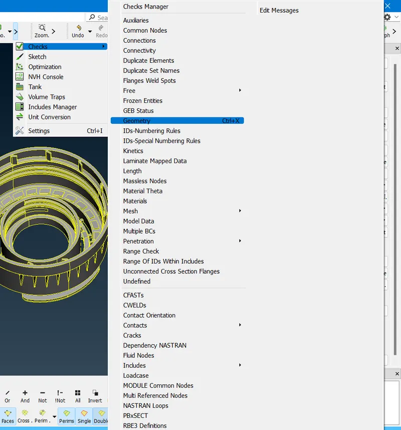
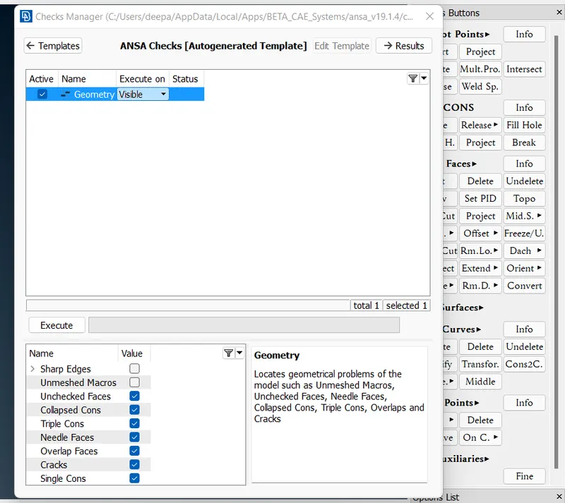
Fig:Geometry Checks
- If any error occurs then fixes are applied to remove them using autofix by selecting them all at once and applying fix to perform Autofix otherwise errors are manually fixed.
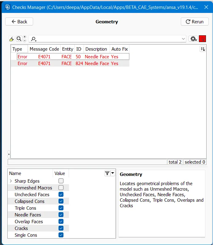
Fig:Before Fix
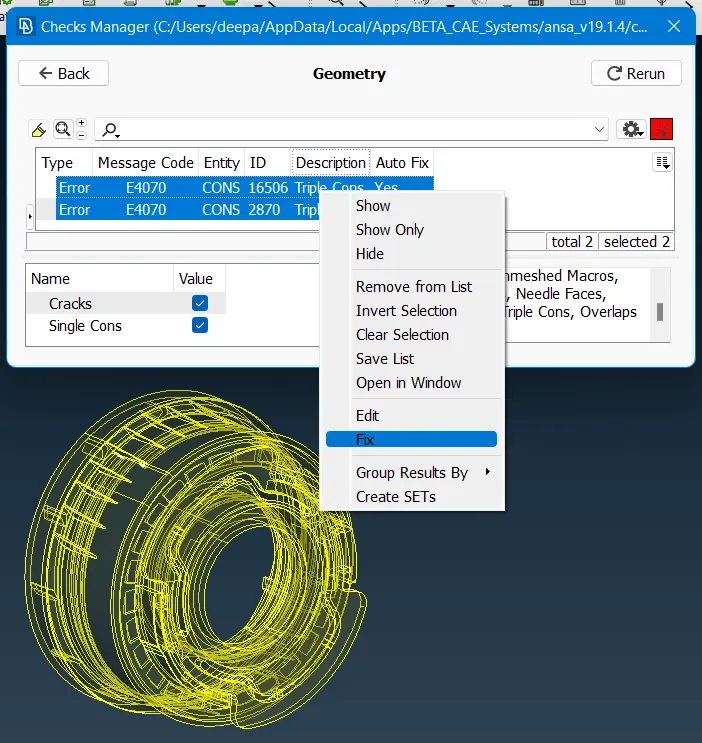
Fig:Applying Fix
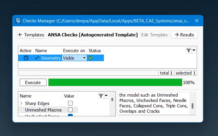
Fig:After Fix
3.Thickness Measurement:
Thickness is measured at different regions of the geometry and stored which helps in extracting the mid surface of the model as a whole.
Utilities>Measure
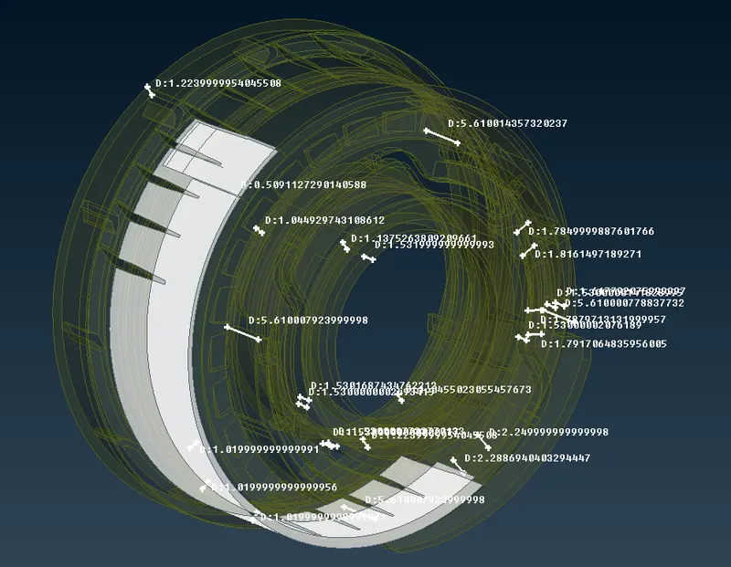
Fig:Thickness Measurement
4.Mid Surface Generation:
There are many different ways by which the mid surface can be extracted and it primarily depends upon shape and thickness of the component. I used different commands to extract the mid surface of various parts of the model.
- Mid surface of simply shaped parts with even thickness can easily be extracted using the offset command
Topo>Offset>Faces
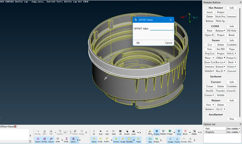
Fig:Offset Command
- Ribs portion having uneven thickness throughout can be captured by using middle single command.
Topo>Middle>Single
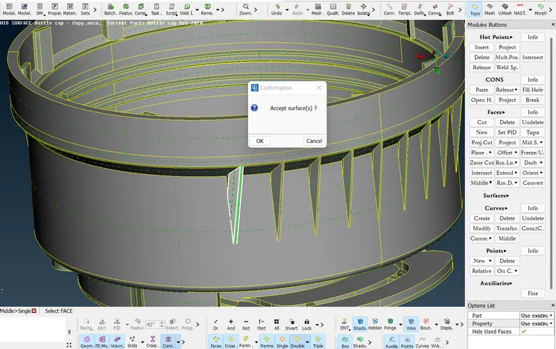
Fig:Middle Single Command
- An other command which is middle multi can also be used to capture ribs present in rotation.
Topo>Middle>Multi
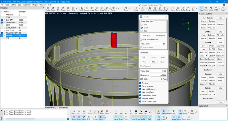
Fig:Middle Multi Command
- Capturing threads is somewhat tricky which is captured using curve middle and then new face is created between projected curve and middle curve in rectangular shape.Trapezoidal shape of threads cannot be captured as it is, so it is captured in rectangular shape.
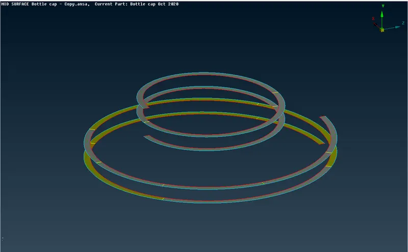
Fig:Mid Surface of Threads Portion
- Features which are repeated like teeths and ribs can be captured using different commands accordingly and then replicate around the circle according to their number with the help of copying a single rib or teeth in 360 degree using Utilities>Transform>copy>select entities>Rotate command while taking two or three points as reference.
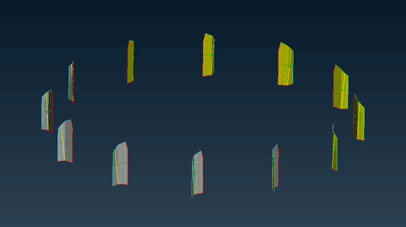
Fig:Mid Surface of Ribs Portion
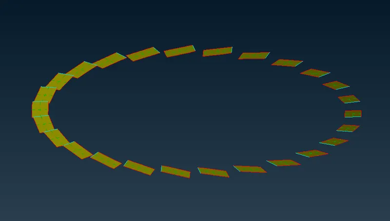
Fig:Mid surface of Teeth Portion
After mid surface generation, geometry is checked again to make sure that there is no error present and then orientation of mid surface is checked.
5.Thickness and Property ID Assigning:
Thickness and property IDs are assigned to different parts of the model. Thickness and property ID assigning helps in further analysis.
Topo>Faces>Set PID>select face>middle mouse click>New>PSHELL>rename>thickness>double right mouse click
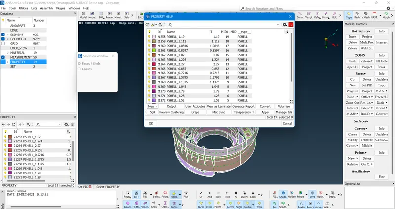
Fig:Thickness and Property ID Assigning
6.Setting Up Hot Points and Quality Criteria:
Hot points are set up according to target or average length decided and quality parameters are set up as per the predefined quality criteria.
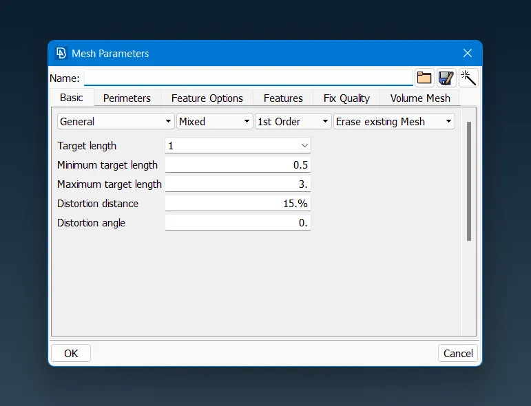
Fig:Mesh Parameters
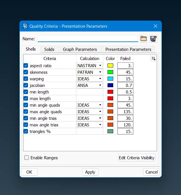
Fig:Quality criteria
7.Meshing:
After quality criteria set up meshing can be carried out as per the predefined quality criteria. For meshing following procedure can be adopted.
Mesh>Mesh Generation>Best>select the surface>middle mouse click
- Reconstruction, split, swap, smooth and paste options are used to improve the mesh quality.
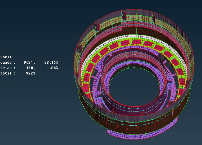
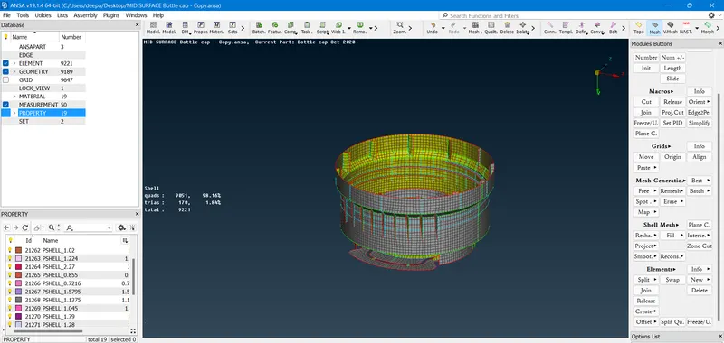
Fig:Meshed Plasic Bottle Cap model
- For Reconstruction and Smooth-
Mesh>Shell Mesh
- For Split and Swap-
Mesh>Elements
- For Paste-
Mesh>Grids
CONCLUSION:
- Successfully extracted the mid surface and meshed the Plastic Bottle Cap model with thickness assignment under given quality criteria.
LEARNING OUTCOMES:
- Learned about taking the mid surface of a plastic component.
- Performed topology clean up and set up quality criteria.
- Learned about using the Middle and rotate option.
- Aware of assigning thickness to plastic components.