Week 3 - Pitot tube
Aim-To simulates a Pitot Static tube and also establish a relationship between Total Pressure and Static Pressure.
Objective-
- To establish a relationship between Total Pressure and Static Pressure.
- For the values of velocity given below calculate the total and static pressures and find the error in percentage for velocity.
Velocity Pressure Density(air)
62m/s 65780 1.225
100m/s 33287 1.225
240m/s - 2817 1.225
Theory-
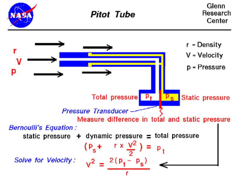
Pitot Tube a device that consists of a tube having a short right-angled bend which is placed vertically in a moving body of fluid (such as air) with the mouth of the bent part directed upstream and that is used with a manometer to measure the velocity of fluid flow.
Although the pitot tube is one of the simplest flow sensors, it is used in a wide range of flow measurement applications, such as air speed in racing cars and Air Force fighter jets. In industrial applications, pitot tubes are used for air flow measurement in pipes, ducts, and stacks, as well as for liquid flow measurement in pipes, weirs, and open channels. While accuracy and rangeability are relatively low, pitot tubes are simple, reliable, inexpensive, and suited for a variety of environmental conditions, including extremely high temperatures and a wide range of pressures.
Pitot tubes are used on aircraft as speedometers. The actual tube on the aircraft is around 10 inches (25 centimeters) long with a 1/2 inch (1 centimeter) diameter. Several small holes are drilled around the outside of the tube and a center hole is drilled down the axis of the tube. The outside holes are connected to one side of a device called a pressure transducer. The center hole in the tube is kept separate from the outside holes and is connected to the other side of the transducer. The transducer measures the difference in pressure in the two groups of tubes by measuring the strain in a thin element using an electronic strain gauge. The pitot tube is mounted on the aircraft so that the center tube is always pointed in the direction of travel and the outside holes are perpendicular to the center tube. (On some airplanes the pitot tube is put on a longer boom sticking out of the nose of the plane or the wing.)
Since the outside holes are perpendicular to the direction of travel, these tubes are pressurized by the local random component of the air velocity. The pressure in these tubes is the static pressure (ps) discussed in Bernoulli's equation. The center tube, however, is pointed in the direction of travel and is pressurized by both the random and the ordered air velocity. The pressure in this tube is the total pressure (pt) discussed in Bernoulli's equation. The pressure transducer measures the difference in total and static pressure.
Measurement =Pt-Ps
For velocity-
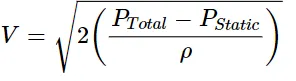
V ^2 = [2 * {pt - ps}] / r
V= velocity of the fluid
Pt = Total Pressure
Ps = Static Pressure
R = Density of the fluid
Procedure-
- Directly import the geometry into the ansys Fluent setup file and define the parameters for the simulation.
- We will conduct three cases of simulation i.e, Velocity= 62m/s, 100m/s, 240m/s and Pressure= 65780 pa, 33287pa, -2817pa.
- Let’s setup fluent parameters for the simulation-
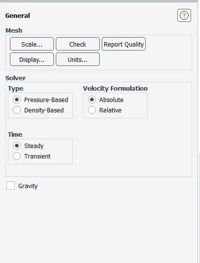
Solver – Steady State solver
Pressure Based
Velocity formulation – Absolute
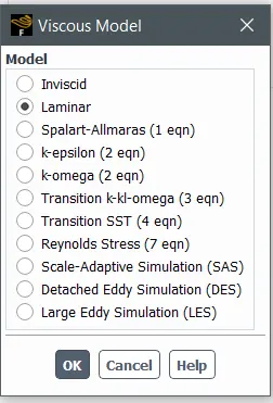
Viscous model – Laminar
Case-1
Boundary conditions-
Velocity Pressure
Inlet—Velocity Inlet – 62m/s 65780 Pa
Outlet—Pressure Outlet – 65780 Pa
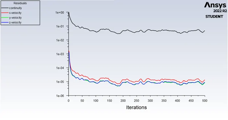
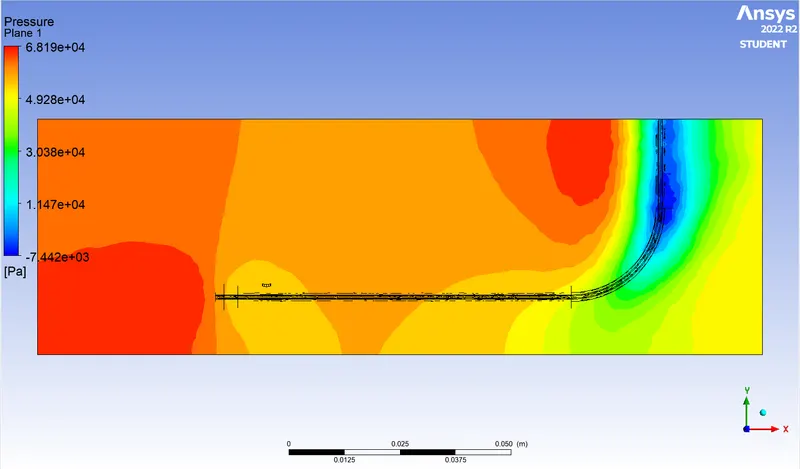

Static Pressure(Pstatic)= 62796.5
Total Pressure(Ptotal) =64744.8
V = 56.39 m/s
Error Percentage = Analytical velocity/Actual Velocity * 100
= 90.5%
Case-2
Boundary conditions-
Velocity Pressure
Inlet—Velocity Inlet – 100m/s 33287 Pa
Outlet—Pressure Outlet – 33287 Pa
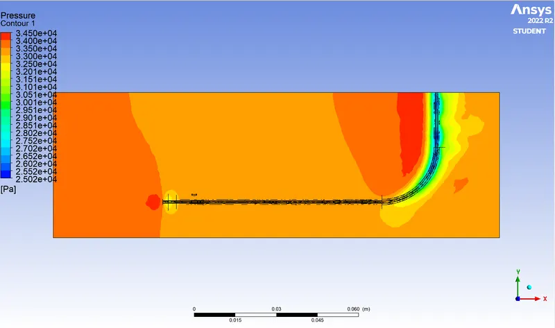

Static Pressure(Pstatic)= 25727.9
Total Pressure(Ptotal) = 30815.2
V= 91.13 m/s
Error Percentage = Analytical velocity/Actual Velocity * 100
= 91%
Case-3
Boundary conditions-
Velocity Pressure
Inlet—Velocity Inlet – 240m/s -2817 Pa
Outlet—Pressure Outlet – -2817 Pa
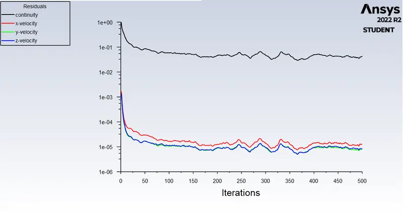
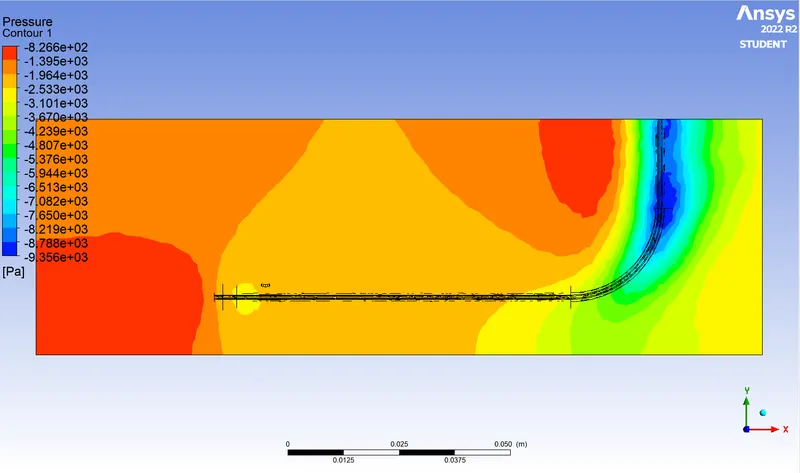

Static Pressure(Pstatic)= -63670.867
Total Pressure(Ptotal) =-34231.526
V=219.23m/s
Error Percentage = Analytical velocity/Actual Velocity * 100
= 91.25%
Data Table
| Actual Velocity | Analytical Velocity | Static Pressure(Pa) | Total Pressure(Pa) | Error% |
| 62 m/s | 56.39 m/s | 62796.5 | 64744.8 |
90.5% |
| 100 m/s | 91.13 m/s | 25727.9 | 30815.2 | 91% |
| 240 m/s | 219.23 m/s | 63670.8 | 34231.5 | 91.25% |
Conclusion-
The pitot tube simulation is carried out with different velocities to predict the static and total pressure at the outlet. The variation of error is marginal and lies within the acceptable region.