Week 3-Meshing of Hood Challenge
Objective
For the given CAD model of an automobile hood -
- Extract the mid-surface
- 2D mesh
- Apply thickness
Follow the below-mentioned quality criteria, mesh the component given below and assign thickness:
Target Element Length = 5 Units
| S.No. | Criteria | Value |
|---|---|---|
| 1 | Aspect Ratio | 5 |
| 2 | Skewness | 45 |
| 3 | Warping | 15 |
| 4 | Taper | 0.5 |
| 5 | Min. Length | 2 Units |
| 6 | Max. Length | 8 Units |
| 7 | Min angle Quad | 45 |
| 8 | Max angle Quad | 135 |
| 9 | Min angle Tria | 20 |
| 10 | Max angle Tria | 120 |
| 10 | Tria % | 10 |
CAD Model
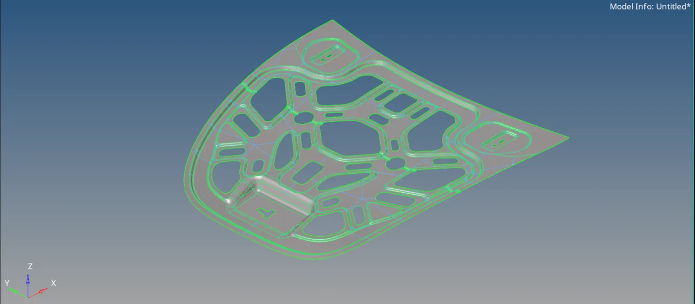
Procedure
1. Perform geometry check
a. Go to appearance → uncheck shared and suppressed box → Change appearance to wireframe
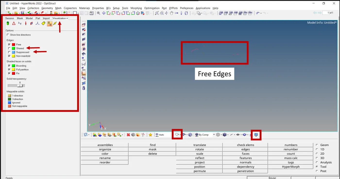
Clearly we can see that there are free edges
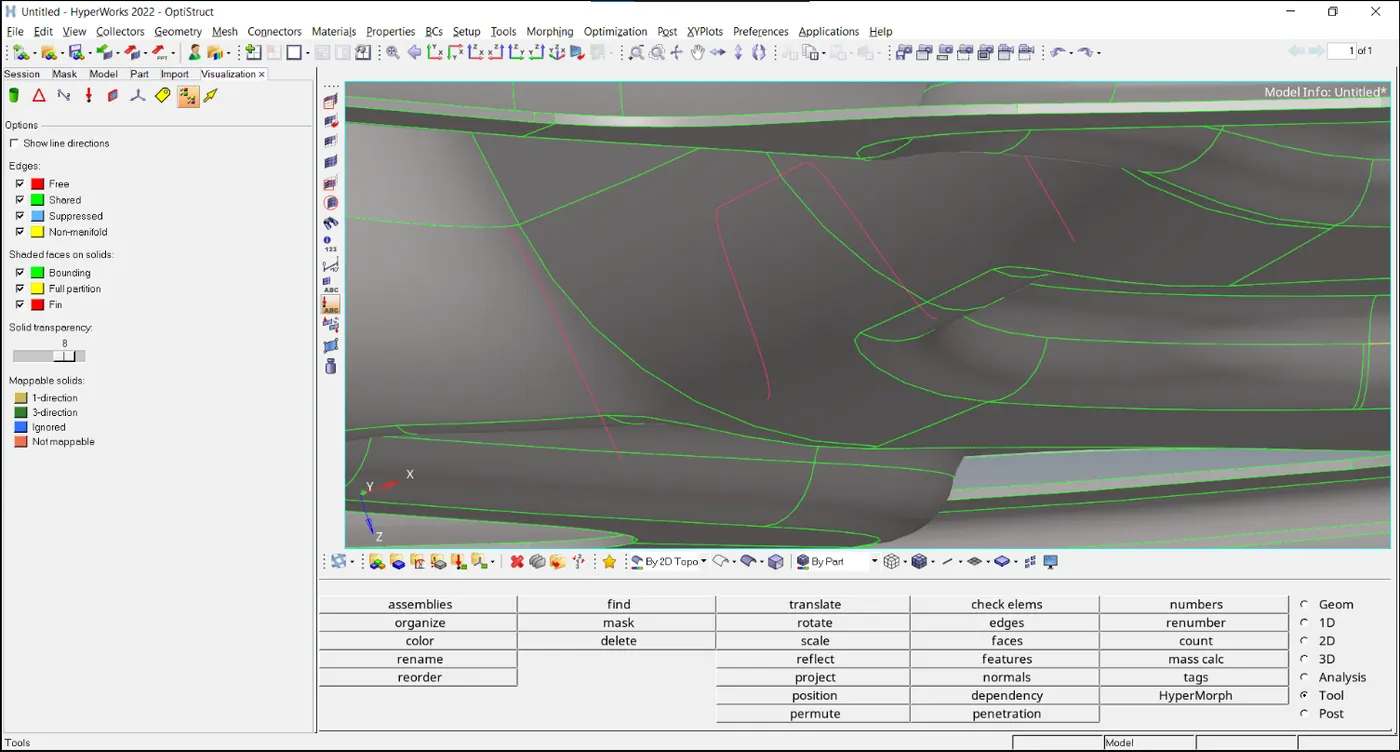
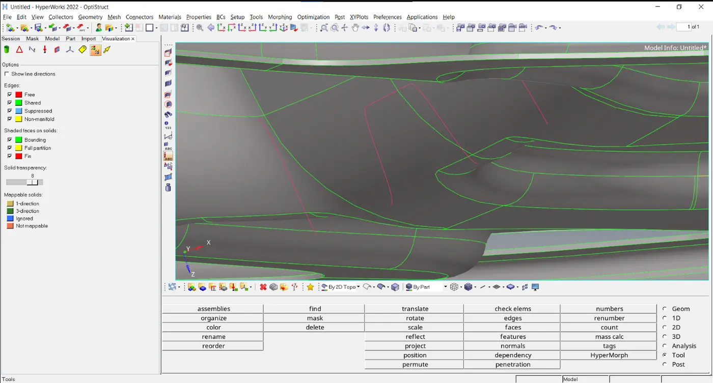 Red lines indicate free lines ⇒ delete the lines
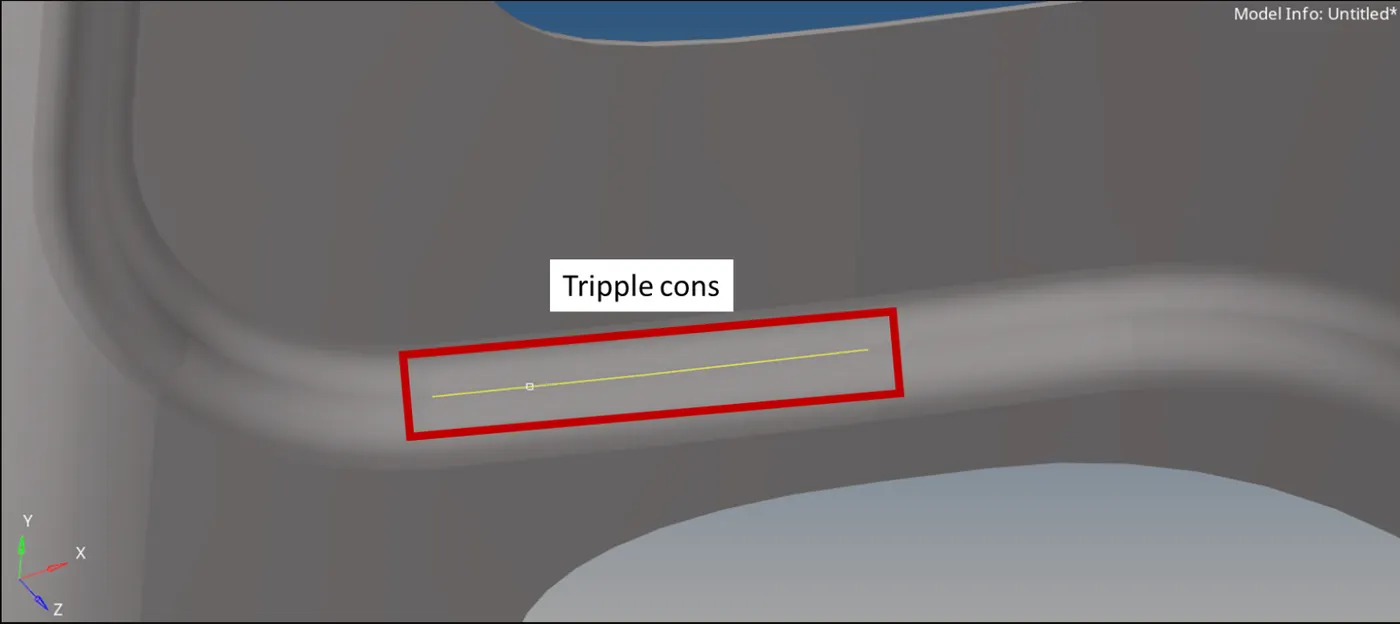
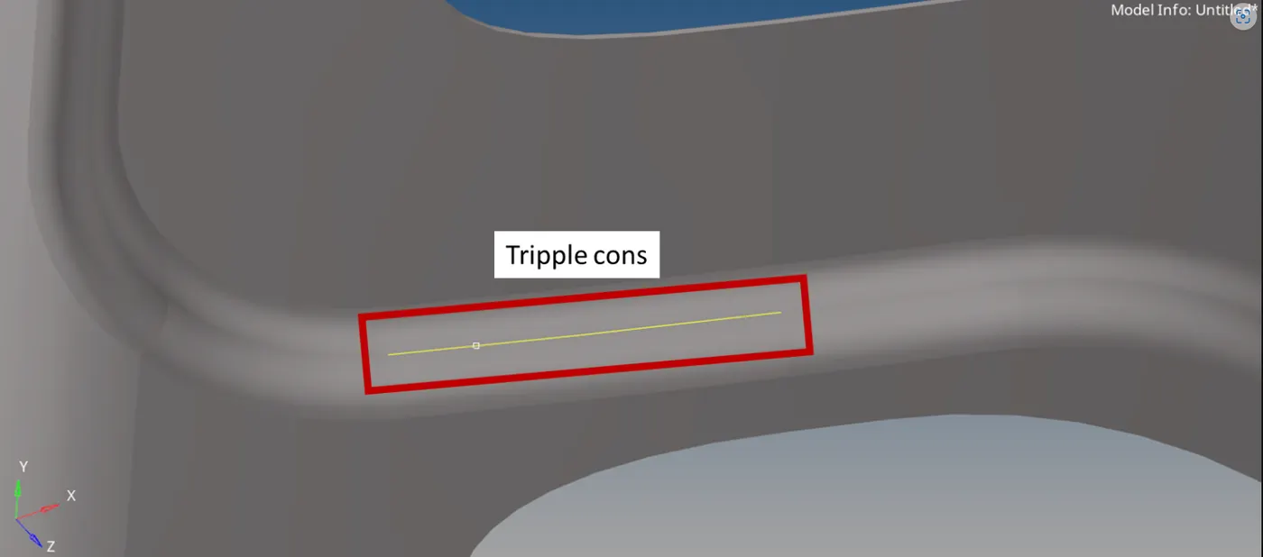 Triple cons means, there are multiple faces ⇒ delete the faces/ toggle the edges
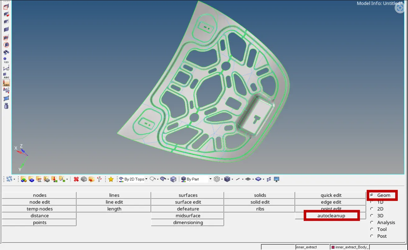
b. Autocleanup ⇒ Geom>autocleanup

2. Perform mid-surface
a. Geom→midsurface ⇒ go for automid-surface
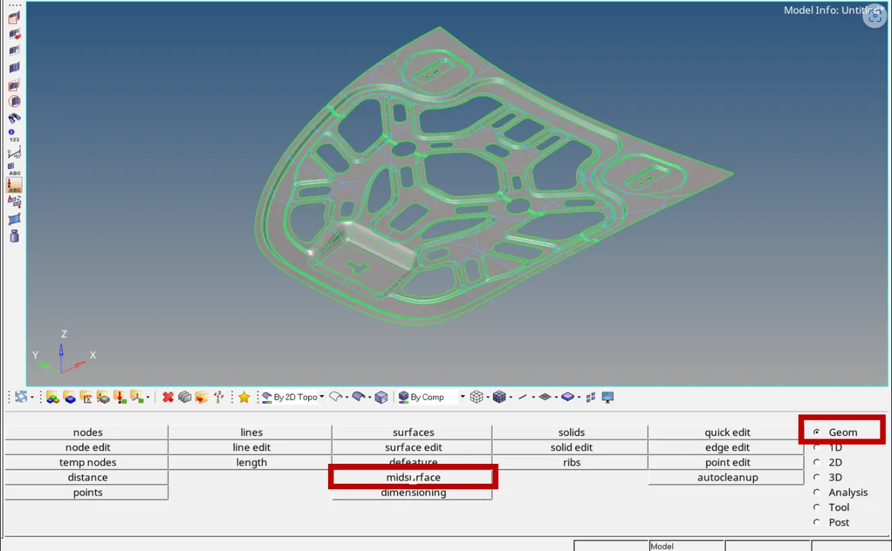

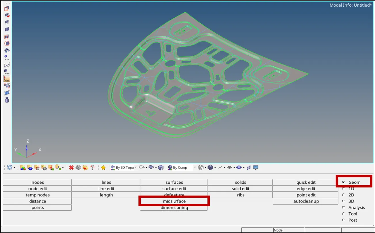 b. A new component as Middle surface will be created
3. Check whether the mid-surface is symmetric, if yes spit the model in two half and we can reflect the FE in other half
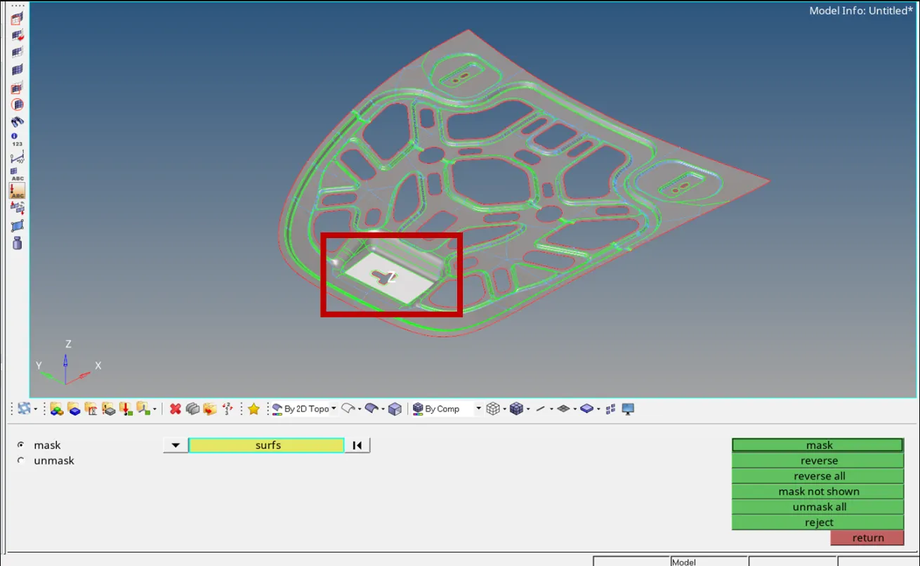 Mask the highlighted face such that model becomes symmmetric.
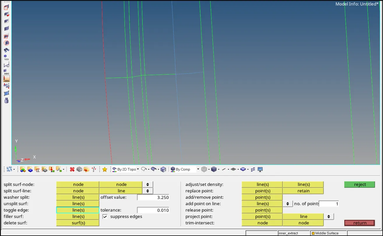 Toggle the edges such that half of the geometry can be masked
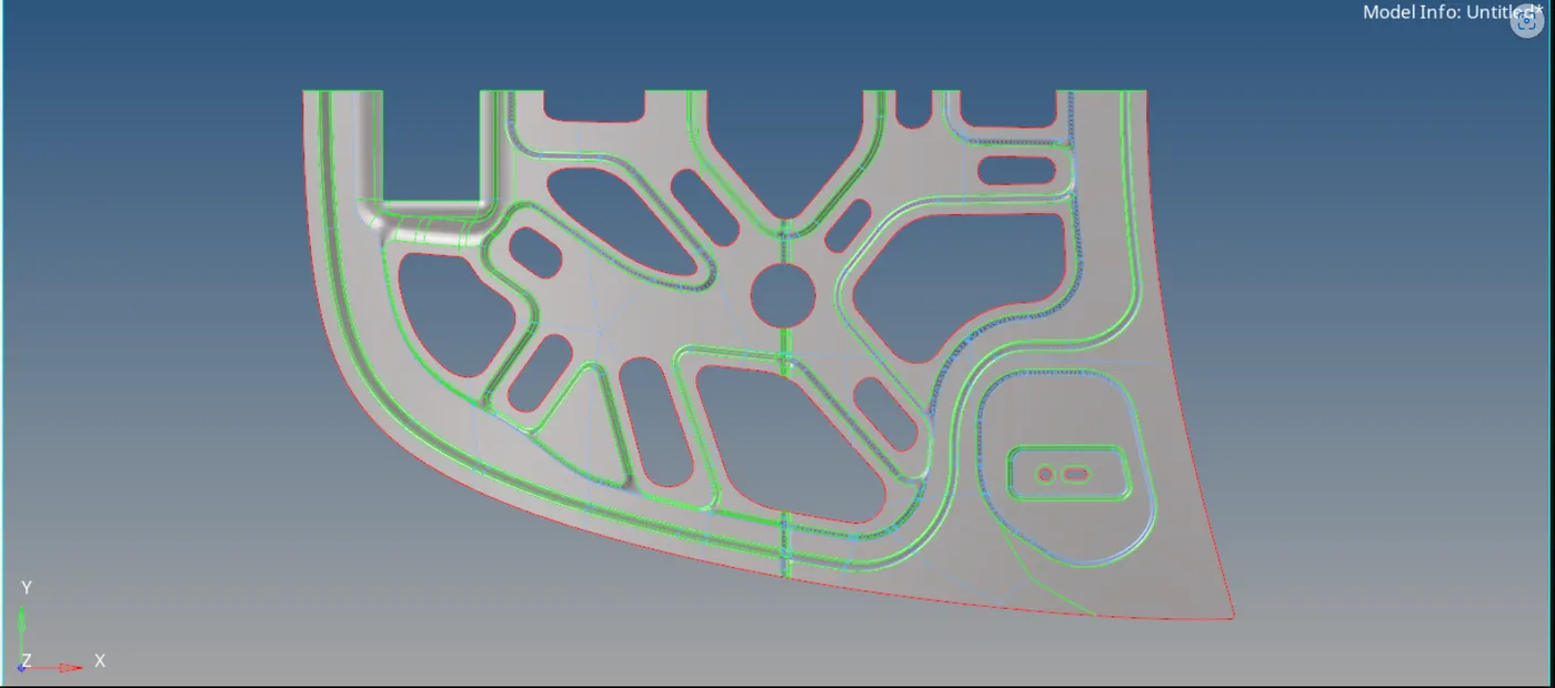
4. 2D shell meshing
a. F12 is the 2D mesh panel

b. Create a new component “Mesh_2D” this will store all the shell mesh
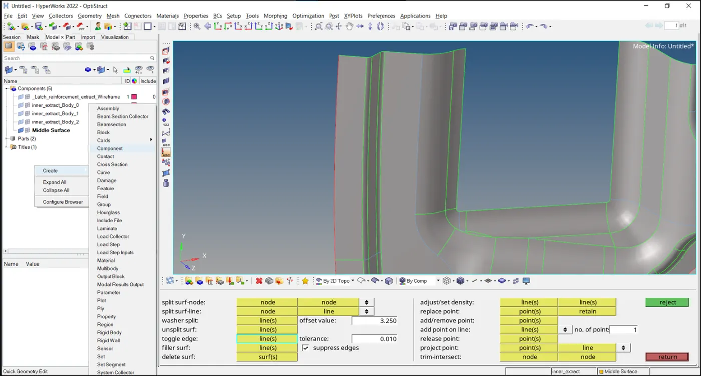
c. Start by meshing the outside surface
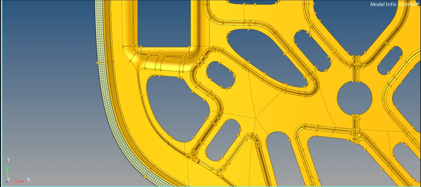
d. It is important to mesh the difficult features first and then proceed for the simple plane surfaces
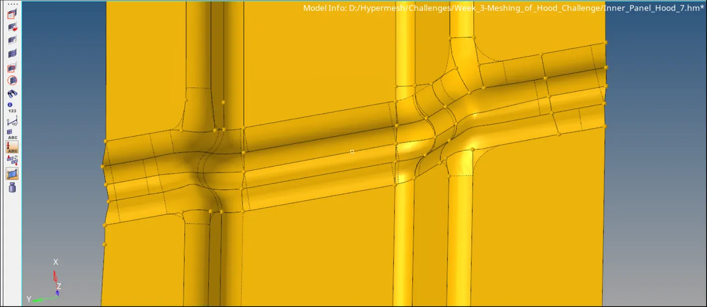
e. Split the feature surface in such a way that it can be covered easily with quads also avoiding the fillet areas with trias
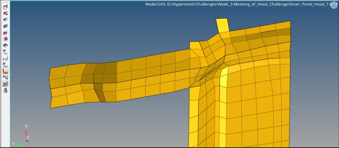
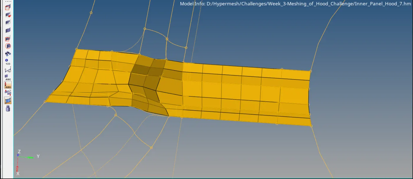
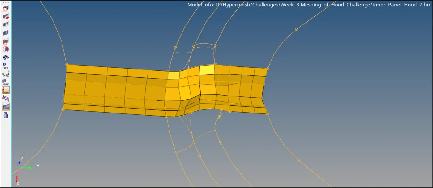
f. Capture all the fillets first
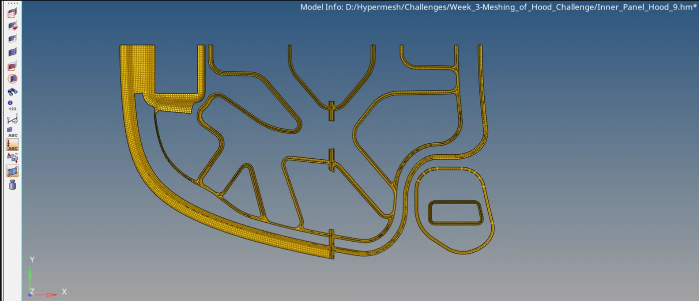
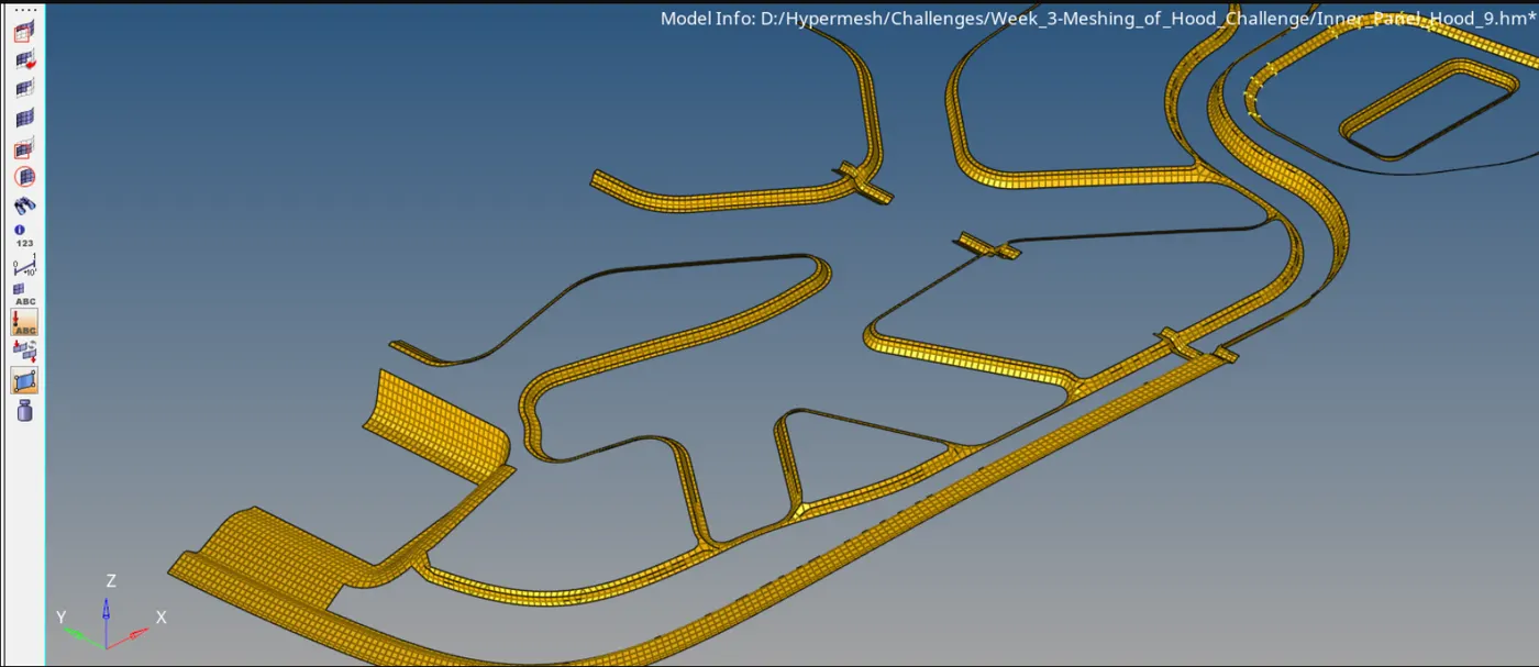
g. Remove the opposite trias
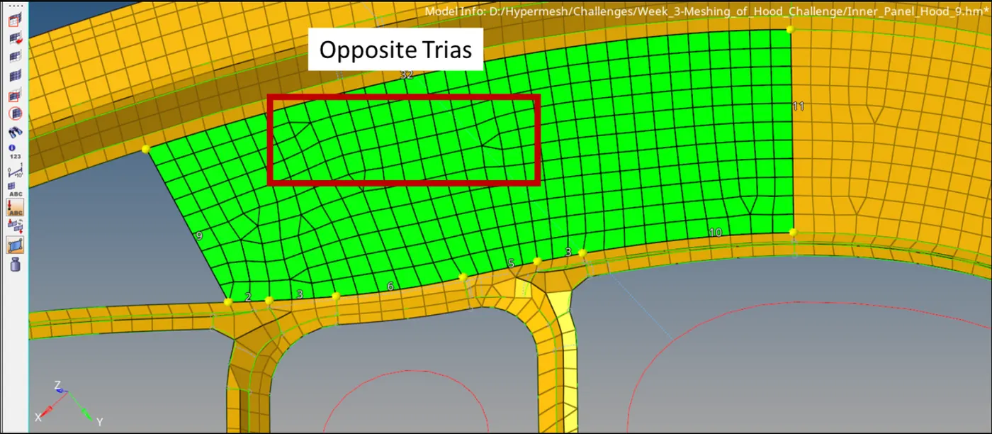
h. Below we can see the trias which are at the fillet location and also opposite trias
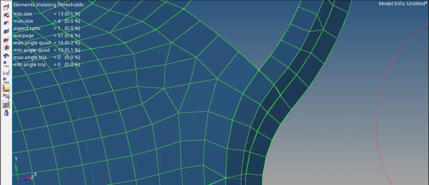
i. To remove this use the swap edge
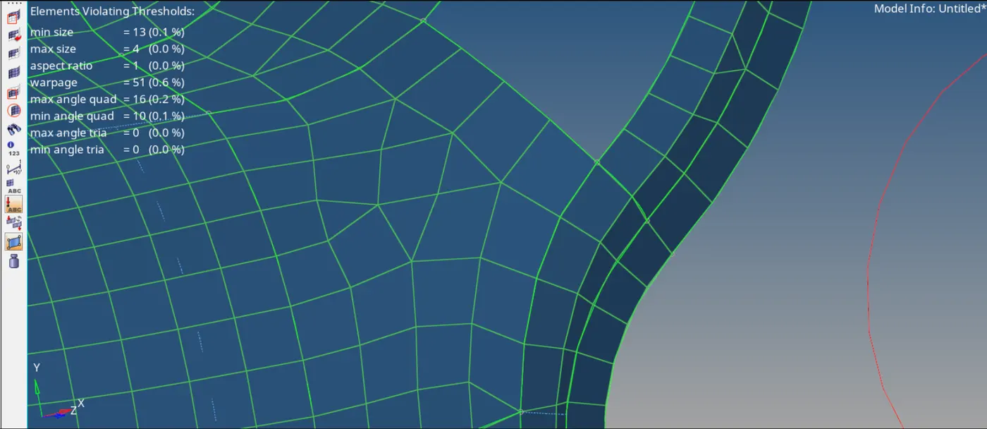
j. All tria has been removed and then use element optimization
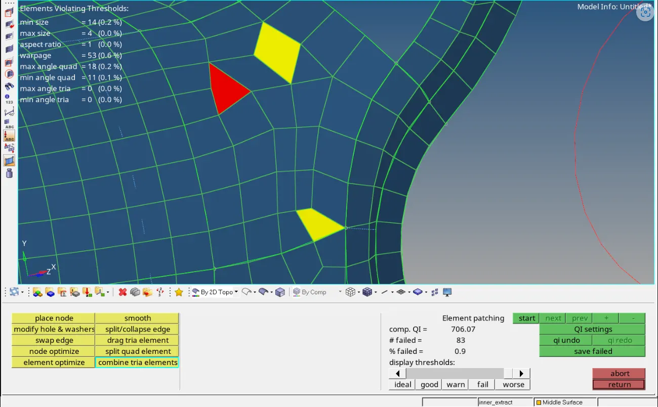
k. Below tria elements can be removed by drag tria option
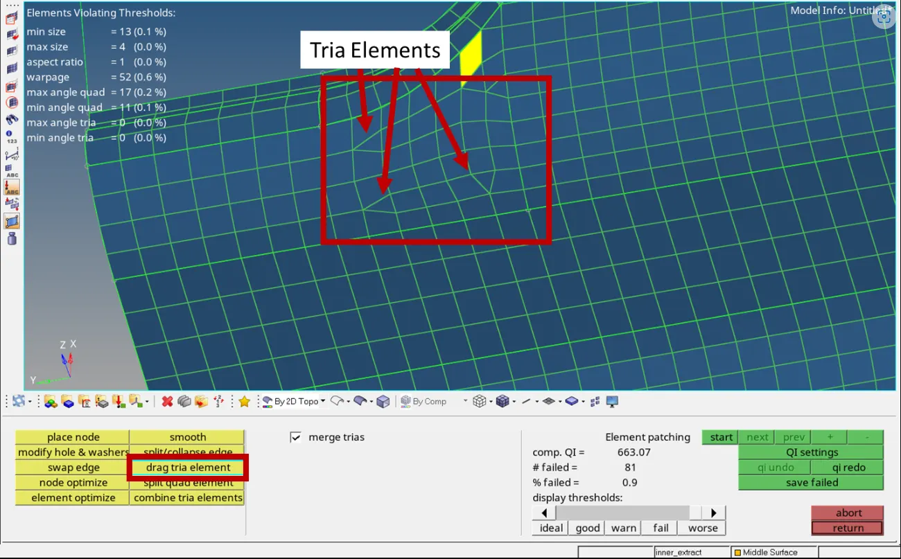
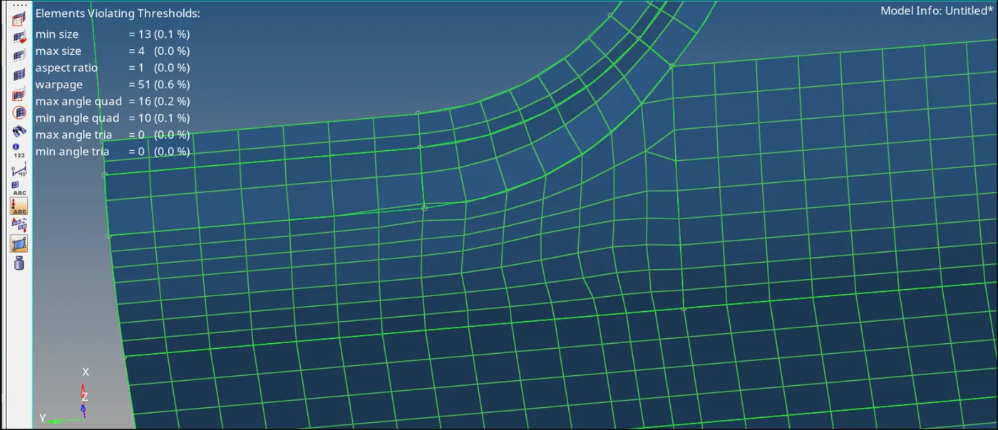
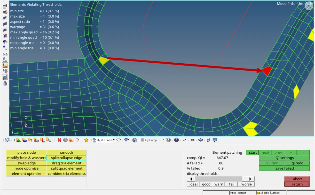
l. Drag this tria to the other annotated end
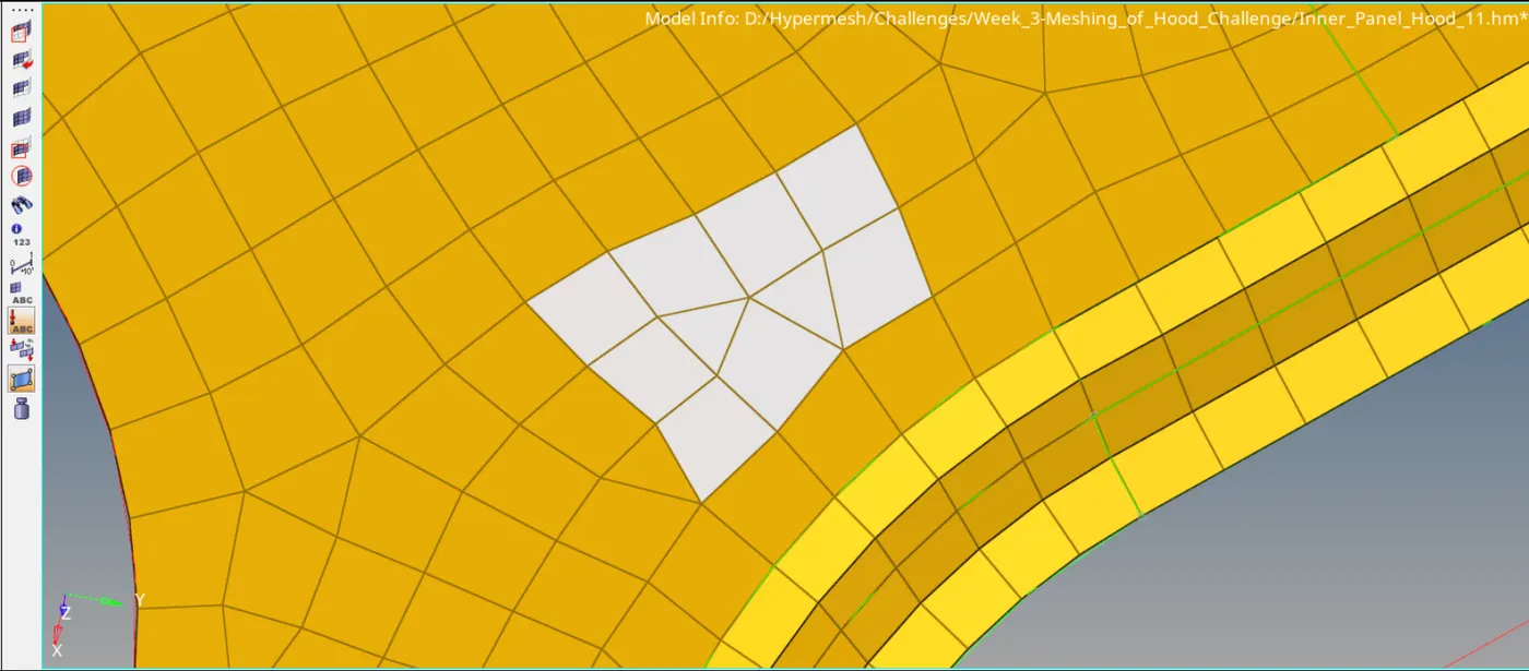
m. Adjacent trias has to be removed
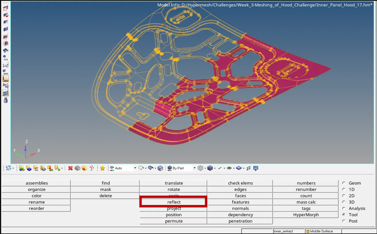
5. Reflect the completed mesh to the other half
a. Use Tool→Reflect→select the elements and define a plane with nodes N1, N2, N3

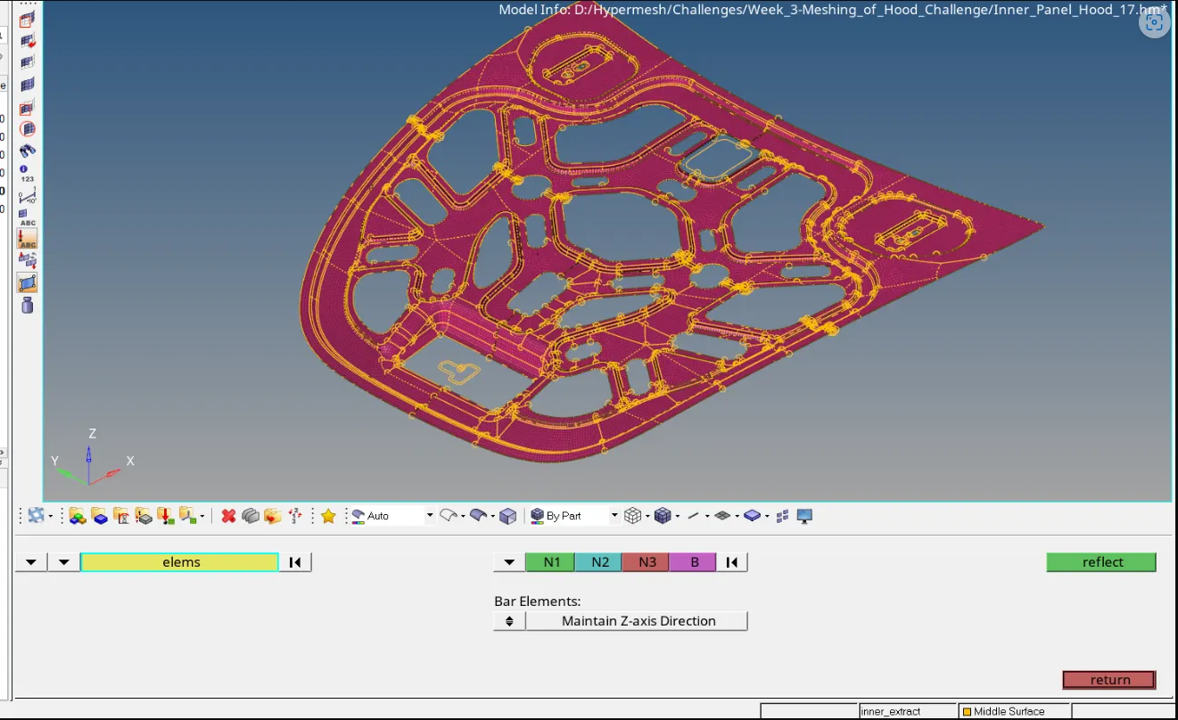
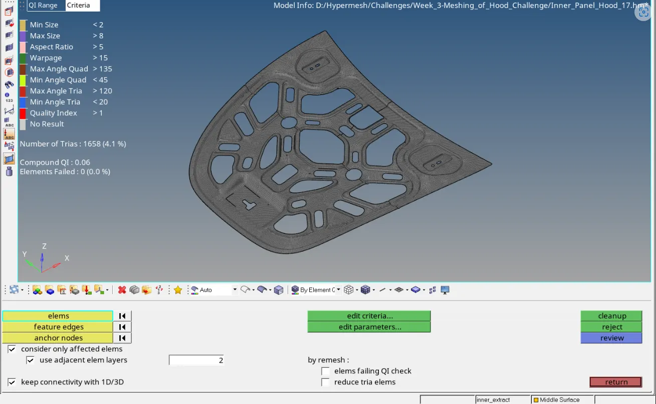
6. Element Quality Checks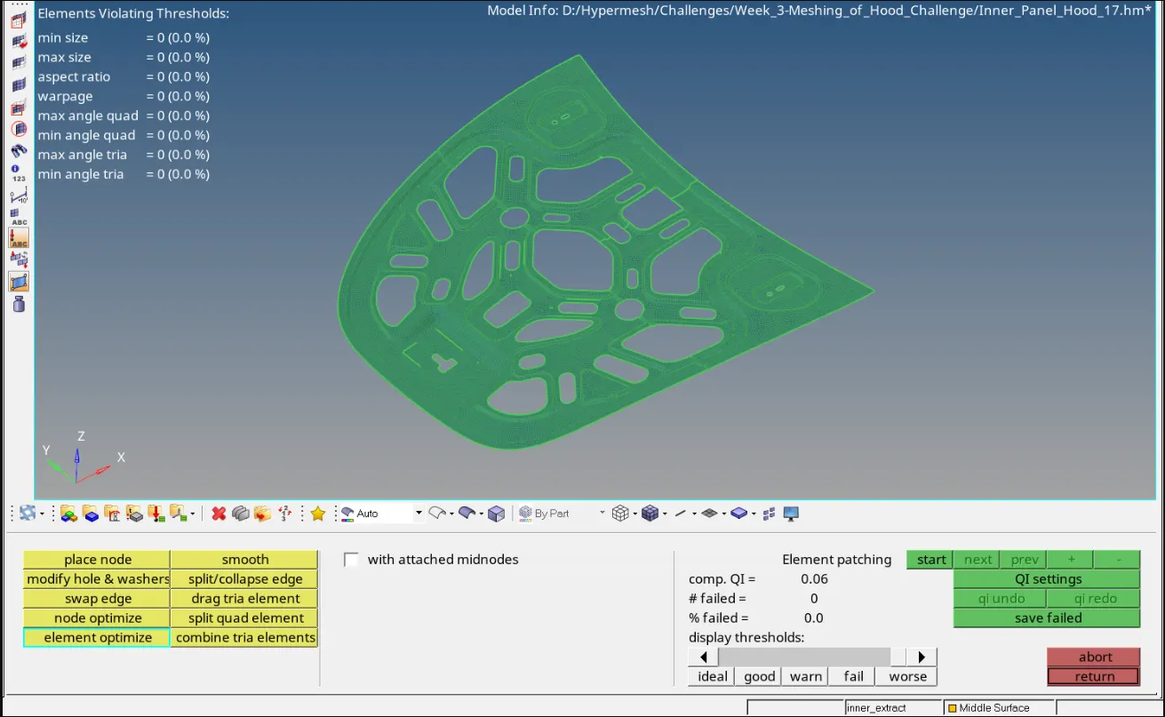 We can check that there are no elemental failure
7. Applying thickness
a. As a final step apply the thickness to the shell mesh
b. Create a new property
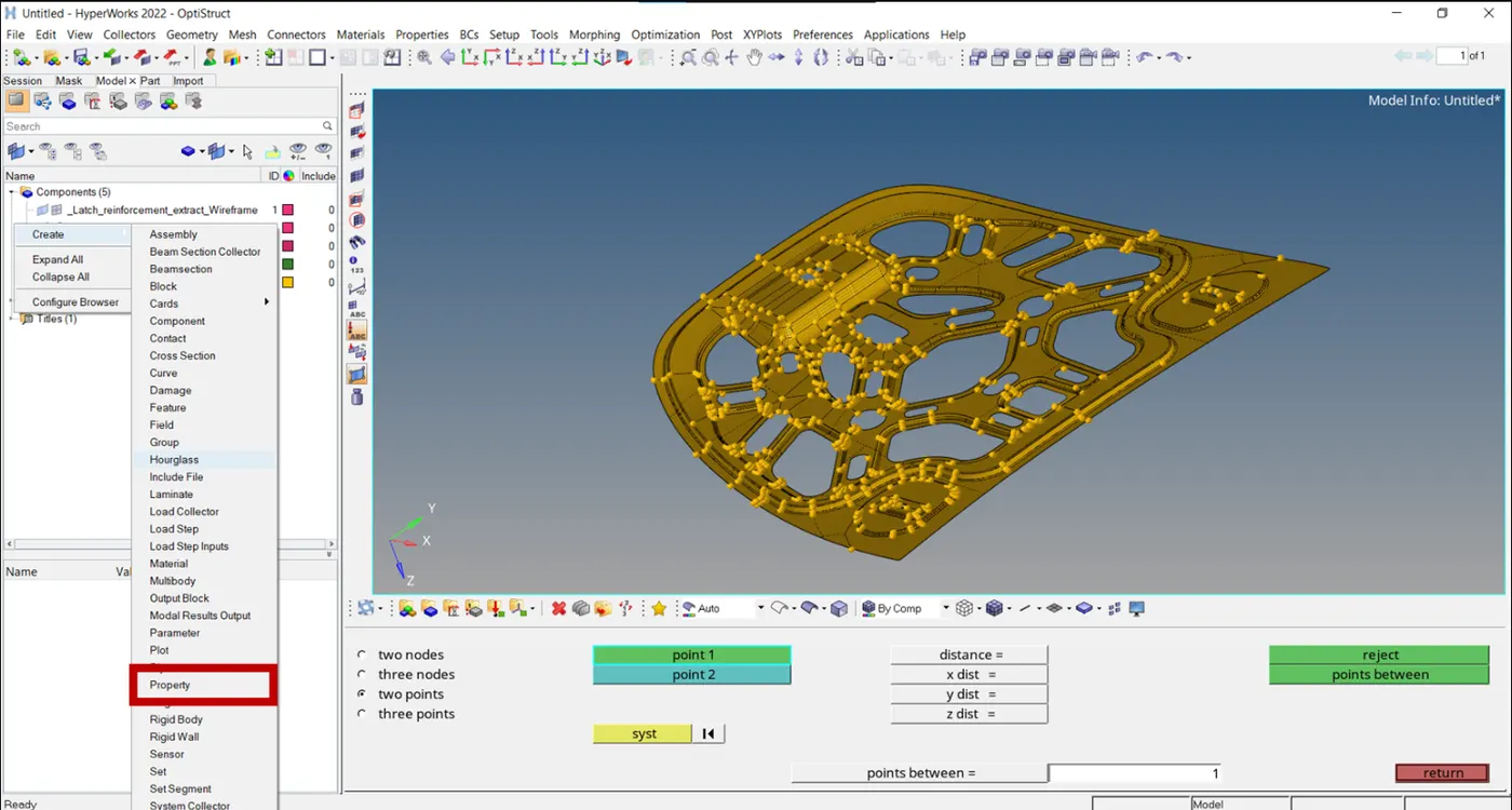
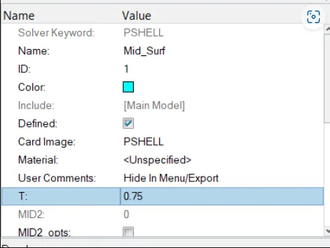
c. Double click on property and give the thickness value of 0.75
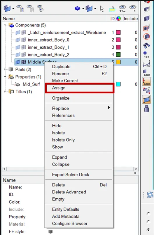
d. Right click on the middle surface component and assign
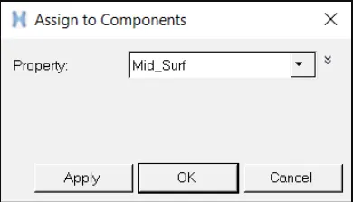
e. Select the mid_surf property and apply
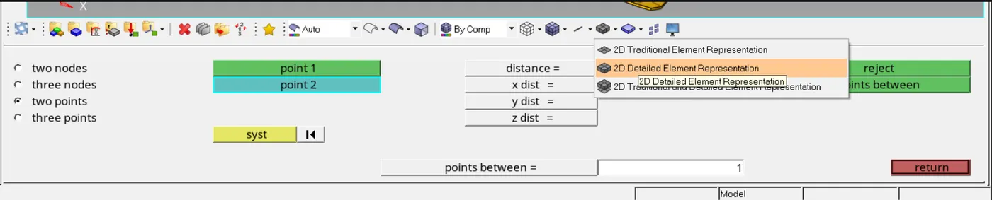
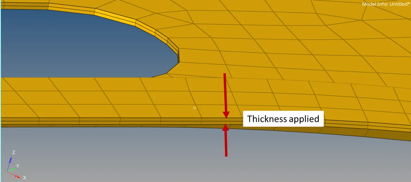
f. To check whether thicknes applied successfully turn on 2D detailed representation
8. Conclusion
- The CAD model was meshed with all the required element criteria
- % tria is less than 10%
...