Week 3 - Geometry simplification of an Electronic enclosure assembly
Geometry Simplification of an Electronic Enclosure Assembly
AIMS AND OBJECTIVES:
- The given model of an electronic enclosure assembly is to be simplified for converting it into icepack geometry. The CAD model is to be initially loaded into SpaceClaim in the created workflow of the Ansys workbench. The model is then simplified to be loaded into Icepack and checked for interference as well.
- The different levels of simplification are to be explained and the imported geometry has to be classified into focus, necessary, periphery, and dispensable bodies.
- In the simplification stage, SpaceClaim commands have to be used to defeature the enclosure and similarly the icepack commands to convert the CAD shapes into icepack primitive shapes.
Geometry Provided: Power Board Assembly
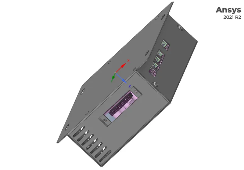
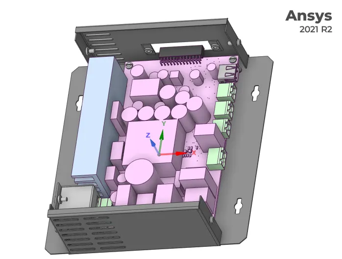
Levels of Simplifications:
There are 4 levels:
Level 0 - creates bounding box based on maximum and minimum coordinates of the geometry
Level 1 - non-polygonal shapes like cuboid and cylinder fit are used to capture and convert such shapes into icepack primitive shapes.
Level 2 - polygons are used here
Level 3 - CAD block is directly converted to icepack object.
Types of Bodies:
Focus bodies - bodies of greatest interest in analysis and that emit or dissipate some amount of heat.
Necessary bodies - they have some effect on focus bodies (eg: enclosure)
Peripheral bodies - their influence on the focus body is uncertain.
Dispensable bodies - they have no effect on focus bodies.
Procedures:
- In the analysis, we do not have to consider the whole geometry. Certain components do not take part in the analysis and hence can be omitted. Similarly, some features like fillet and chamfer can increase the complexity of the model in the analysis and makes it computationally expensive, and can hence be removed.
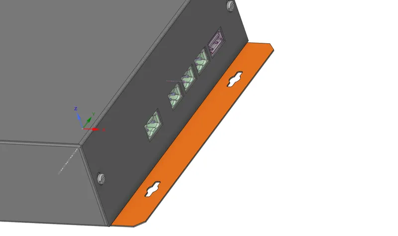
- The enclosure is a necessary body here. In the enclosure, the extended part as highlighted in the figure below can be removed as it has no importance in the analysis.
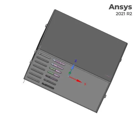
- Defeature fillets and other curvatures from the geometry to simplify it.
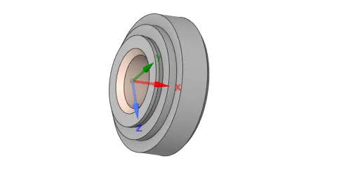
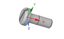
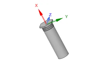
- The screws, washers, and nuts are dispensable bodies and can be eliminated from the model.
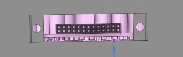
- The opening in the figure below is the provision through which the connector can be connected and hence there will not be any exchange of heat through the same. Hence, the opening can be filled using the fill/pull command.
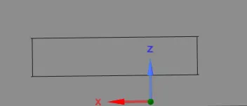
- Similarly, certain areas of the geometry can be observed with unwanted cuts/slots as in the figure below and can be closed using the fill command.
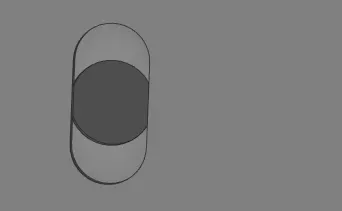

- The small components, seen beneath the PCB board as in the figure below dissipate only a negligible amount of heat and are therefore dispensable bodies. They can be removed from the geometry to make the meshing process less complex. Similarly, there are a few small parts on the upper surface of the PCB as well and those can also be deleted.
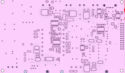

- The 'identify objects' command under the workbench tab of SpaceClaim can be used to convert the CAD shapes into icepack blocks. The components on the PCB are separated into individual blocks using the 'split body' command before being converted into icepack blocks.
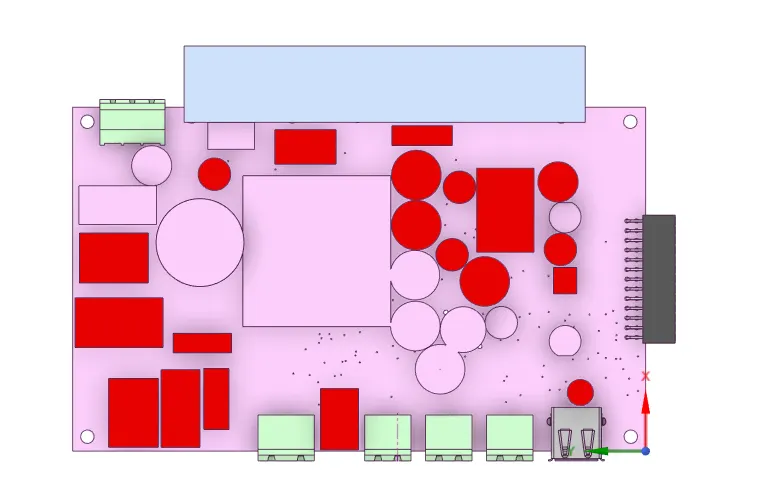
- In the figure above, it can be observed that certain parts could be identified as icepack objects by using the 'identify objects' command but the rest of the parts still remain as non-icepack bodies. The remaining parts can manually be converted into icepack objects using different levels of the 'Icepack Simplify' command. The figure below shows the PCB with its non-icepack bodies after the above step.
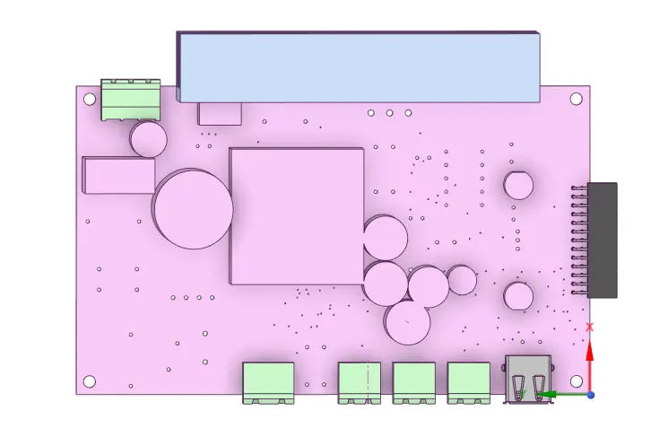
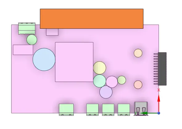
- The individual bodies in the above figure can be converted now using different levels of the 'Icepack Simplify' command. The shapes with interferences are separated by using the 'split body' command beforehand and suitable levels are applied. While simple box shapes are applied with Level 0 to create bounding boxes, Level 1 is applied to cuboidal or cylindrical shapes. Also, the PCB board is applied with Level 0 simplification. The figure below shows the bodies after the application of Level 0 and Level 1 icepack simplifications to cuboidal and cylindrical shapes.
- The heat sink is converted using Level 1 simplification as shown below:
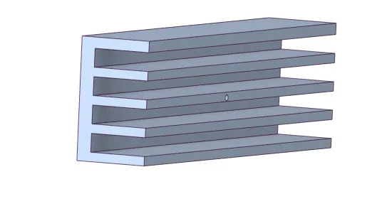
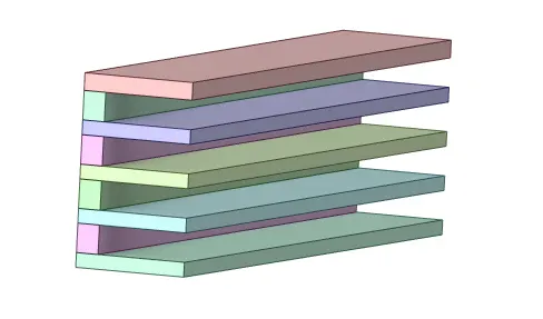
- The adaptor and USB pins as shown below are also simplified using Level 2 polygon fit.
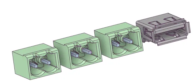
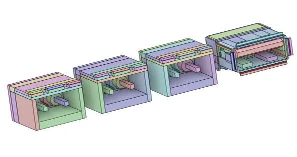
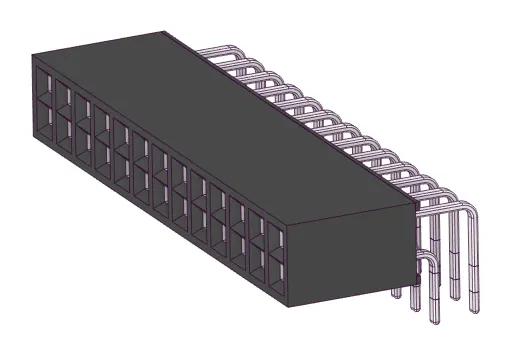
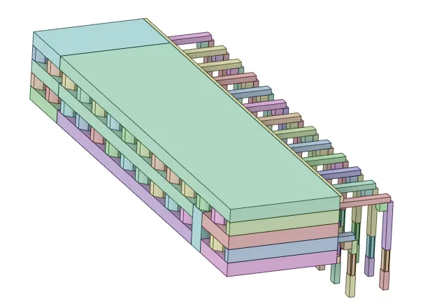
- Also, the connector as shown below is converted into an icepack object using Level 2 polygon fit.
- The figure below shows the converted icepack objects of PCB and its components:
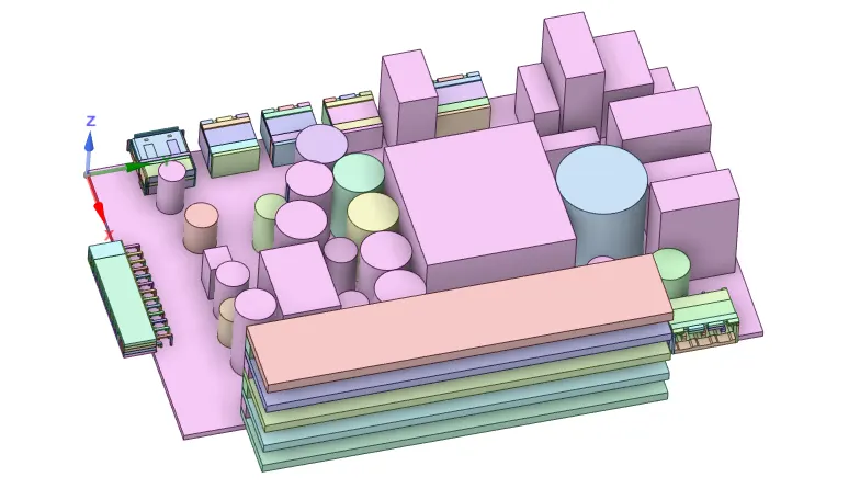
- Now the remaining bodies of the CAD geometry can be simplified. The enclosure part is now left to be converted into the icepack object. The top surface of the enclosure as seen in the figure below is converted using Level 2 simplification.
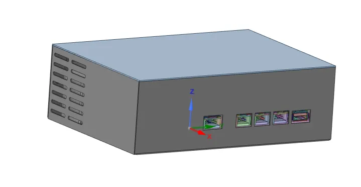
- Now using the grille command under the workbench tab can be created on the selected faces or the regions of interest.
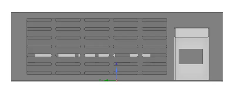
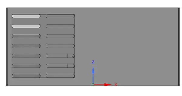
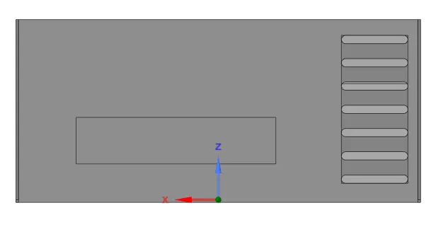
- Similarly, the openings can also be made using the opening command under the workbench tab.
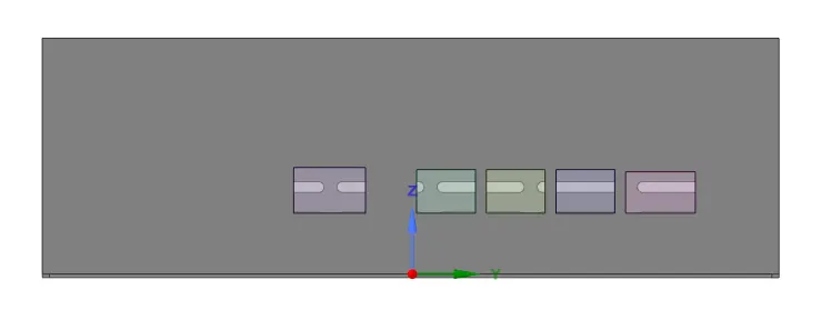
- The remaining non-icepack bodies of the enclosure assembly are simplified accordingly using the suitable levels and the final converted icepack object of the CAD geometry is shown in the figure below.
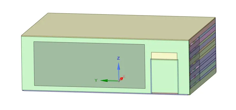
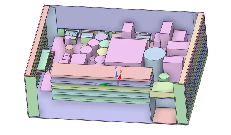
- The converted model can now be saved in a preferred directory as an icepack model which can later be opened using icepack.
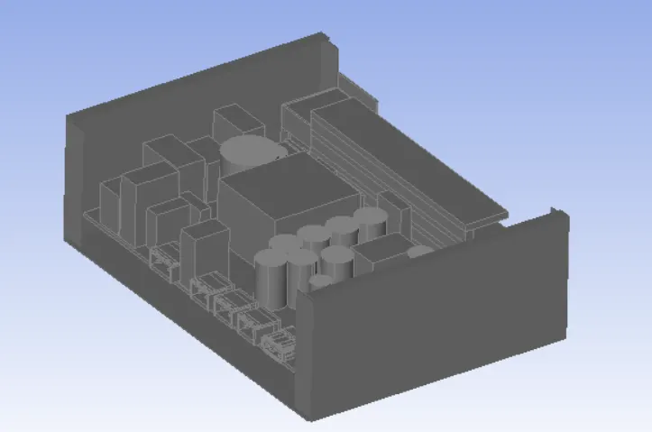
- The model simplified in SpaceClaim can now be shared with the icepack in the workbench flow. The solid shading view of the geometry opened in the icepack is shown in the figure below.
- The above model can be modified in the icepack to capture the correct physics.