Week 3 - External flow simulation over an Ahmed body.
Objective:
- To simulate the flow over an Ahmed body on fluent with a fluid velocity of 25 m/s and default air properties.
- To explain the reason for negative pressure in the wake region and the significance of the point of separation.
- To perform the grid independence test and to calculate the values of coefficient of lift and drag in each case.
Ahmed Body:
Ahmed body is a bluff body that represents a basic passenger car model. It is a simple model over which accurate flow simulation can be performed yet giving important flow features around a vehicle model. It is designed first by SR Ahmed in 1984. The length, breadth, and height of Ahmed body are 1044 mm, 3890mm, and 288 mm respectively. The body has four cylindrical legs underneath which are 50 mm off the ground. The slanted side is around 222 mm with an approximate angle of 40º.
The model helps in capturing and studying effectively the turbulent flow over an automobile with recirculations in the wake region, point of separations, and interaction with the boundary layer. This is majorly used in studying for the designing of a newer vehicle model for the market with a shape that can have optimum drag for effective fuel consumption, road stability.
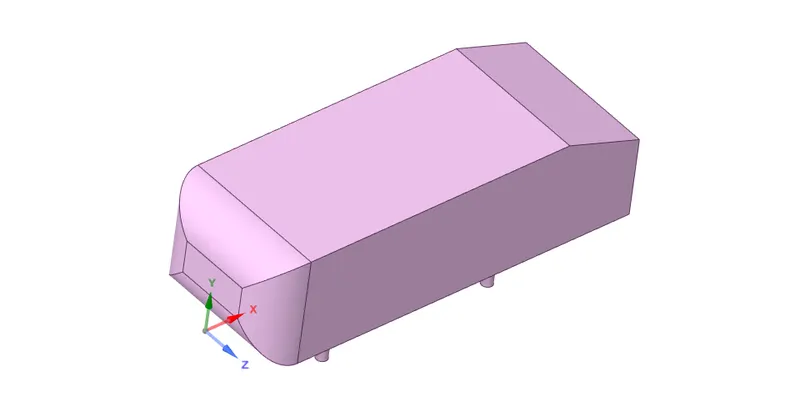
Geometry preparation
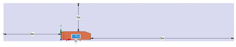
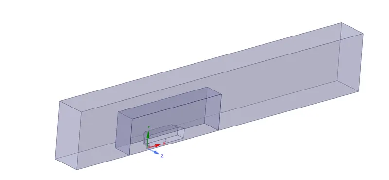
The length, breadth, and height of outer enclosure with respect to the Ahmed body:
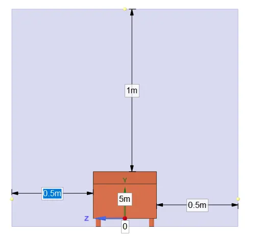
The length, breadth, and height of inner enclosure with respect to the Ahmed body:
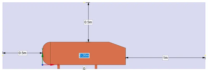
Using the split body tool in SpaceClaim, the whole body is made into half. Since the body is symmetrical, considering only half of the body will be helpful in reducing the simulation time but to give accurate results.
Meshing
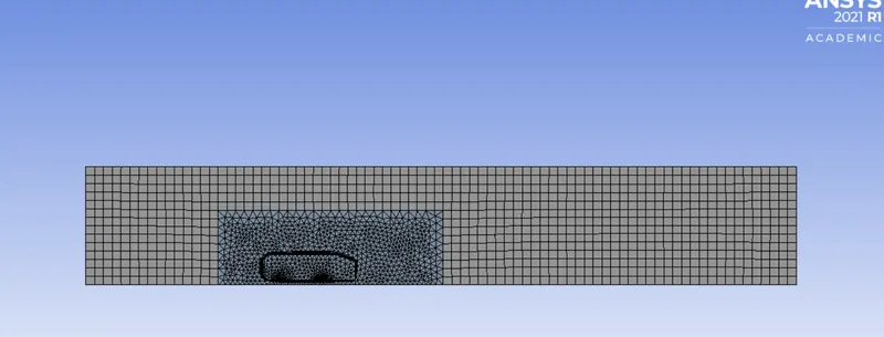
The outer enclosure is made of perfect boxes and is better to use multizone to make hexahedral meshes wherever possible. The inner mesh is more involved in the physics and refined mesh has to be considered. Hence tetrahedral meshes are used inside and also proper sizing is given to enclosures and Ahmed body supports underneath. The region where more refinement is needed is near the wall. Adequate inflation layers are given to the mesh near the wall to fit the surface perfectly so that proper physics can be captured.
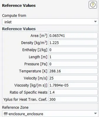
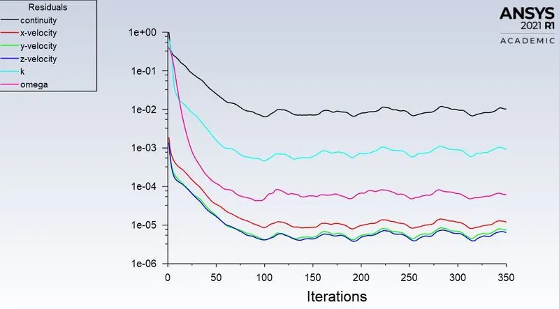
Here, a pressure-based solver is used because the inlet velocity is 25 m/s which is less than 0.3 Mach and the steady-state solver as we are interested to get the final result.
- Case 1 (Baseline): Mesh size of the outer enclosure = 100 mm and inner enclosure = 50 mm
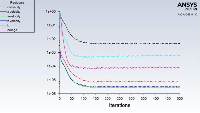
Convergence Plot:
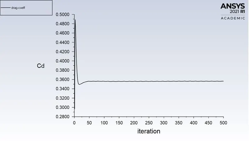
Coefficient of Drag:
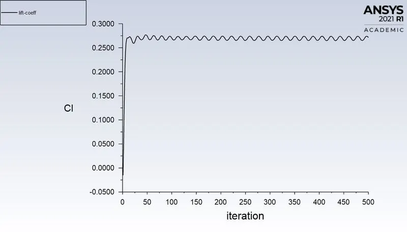
Coefficient of Lift:
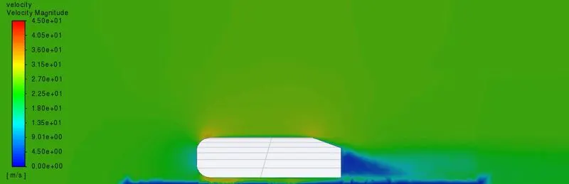
Velocity Contour:
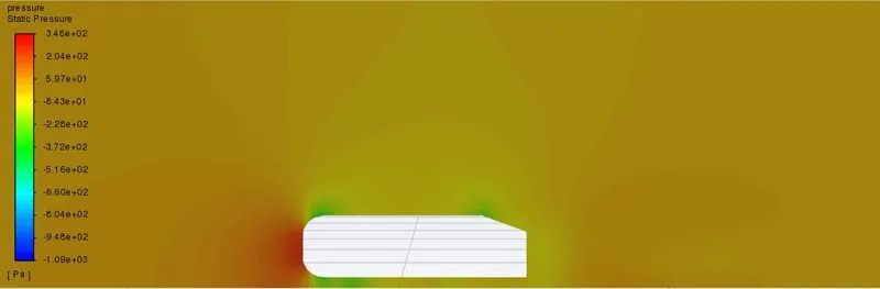
Pressure Contour:
Pressure gradient on Ahmed body:
Vector Plot
- Case 2: Mesh size of the outer enclosure = 80 mm and inner enclosure = 30 mm
Convergence Plot:
Coefficient of Drag:
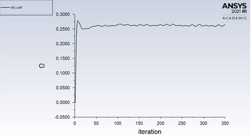
Coefficient of Lift:
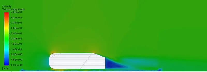
Velocity Contour:
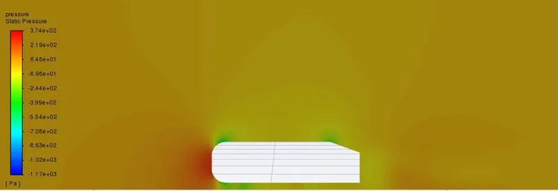
Pressure Contour:
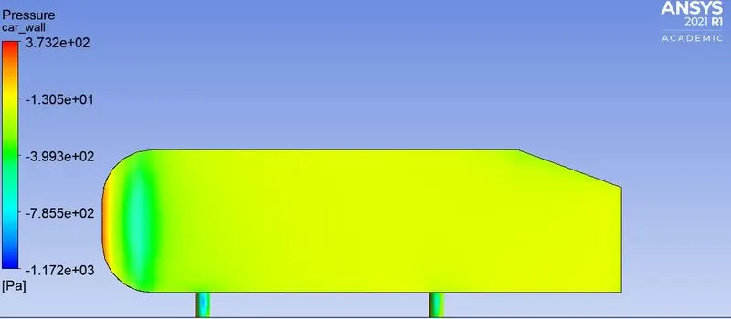
Pressure gradient on Ahmed body:
Vector Plot
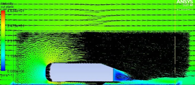
- Case 3: Mesh size of the outer enclosure = 70 mm and inner enclosure = 25 mm
Convergence Plot:
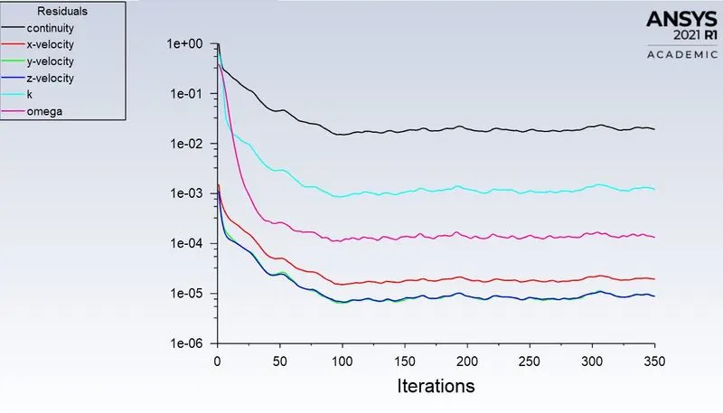
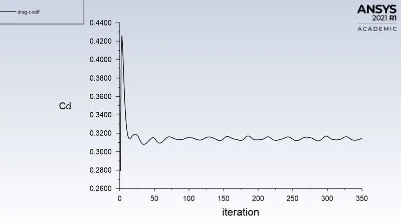
Coefficient of Drag:
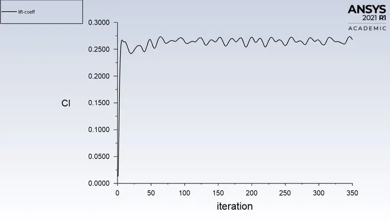
Coefficient of Lift:
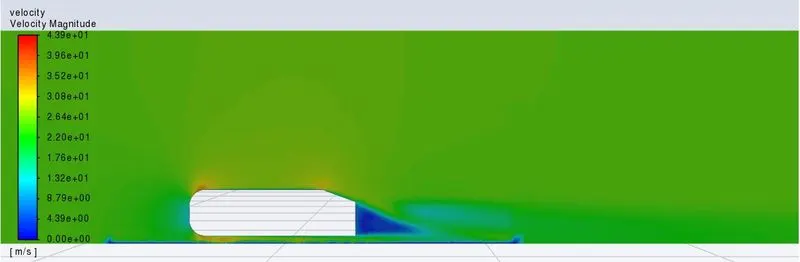
Velocity Contour:
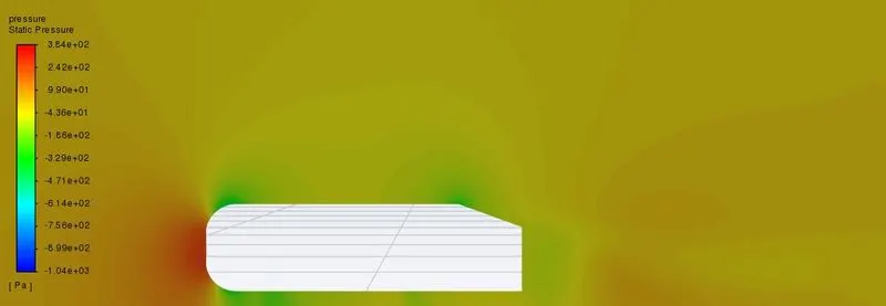
Pressure Contour:
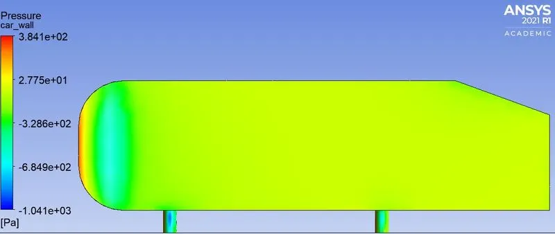
Pressure gradient on Ahmed body:
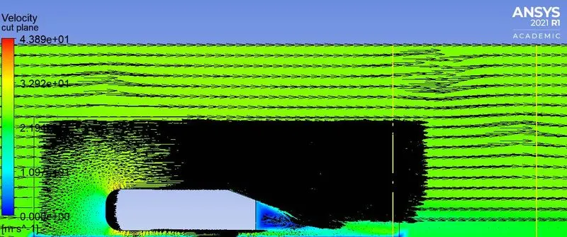
Vector Plot
| Case | Coefficient of Drag (approx) | Coefficient of Lift (approx) |
| 1 | 0.356 | 0.275 |
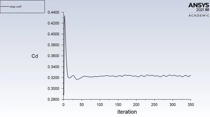
| 2 | 0.326 | 0.27 |
| 3 | 0.318 | 0.275 |
- Grid independent test is done with different mesh sizes in each case for outer as well as inner enclosures. The physics are more accurately captured in second and third cases. The total cell size in the third case is 479234 which is way more than the second case that took only 284793 cells. Hence computational time is more in the third case as compared to the second. Therefore, the second case is optimum and also gives a coefficient of drag value of 0.326 which comes on par with 0.33 as given for validation.
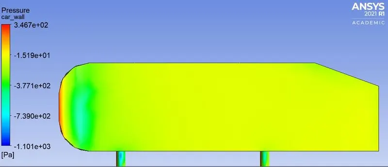
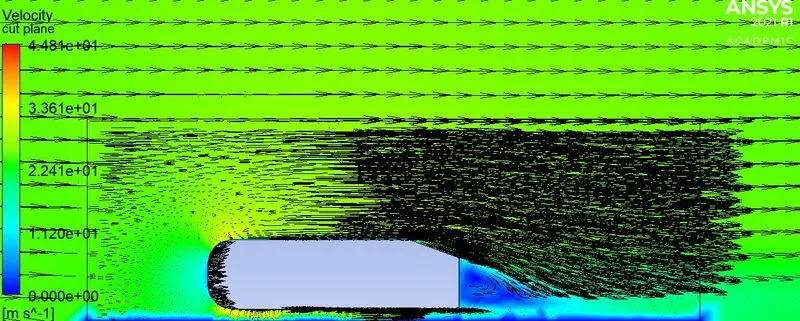
- The reason for the negative pressure gradient is the flow separation at the rear end of the body and the resulted wake region formed. The point of separation greatly depends on the real slant angle of the body. Based on the same, the separation could be delayed or early. In the vector plots, it can be seen clearly the formation of vortices at the rear end, and the same forms a recirculation region so as to make a wake region. The pressure at the recirculation region is so low as compared to the front and the same results in the pressure difference between the two to cause a pressure drag.