Week 3 - External flow simulation over an Ahmed body.
Objective :
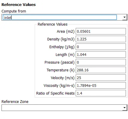
To run the simulation of Ahmed body for the velocity of 25 m/sec with the default air properties in fluent.
In this challenge, answers to the following questions needs to be provided
Q1. Describe Ahmed's body and its importance.
Q2. Explain the reason for the negative pressure in the wake region.
Q3. Explain the significance of the point of separation.
Expected Results:
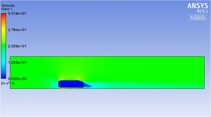
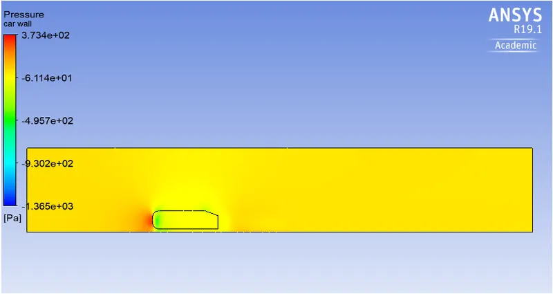
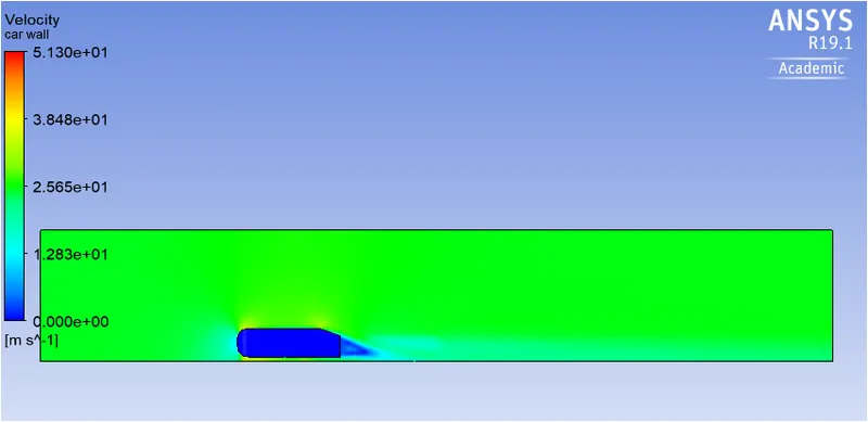
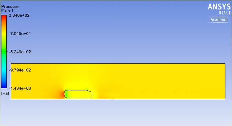
1. Velocity and pressure contours.
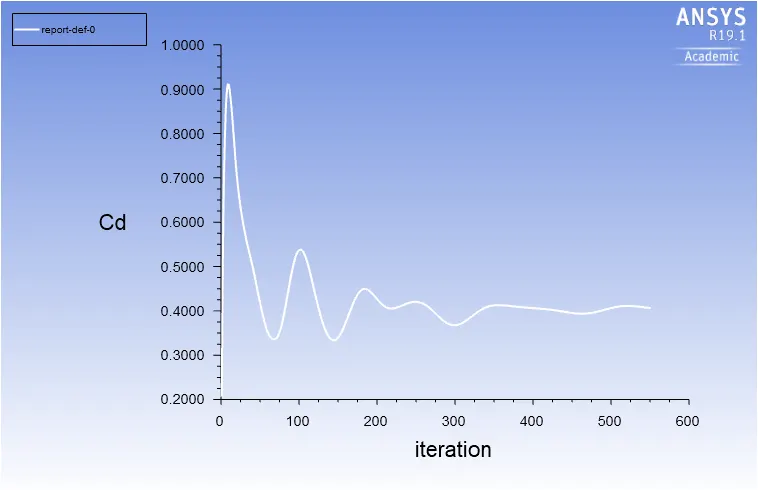
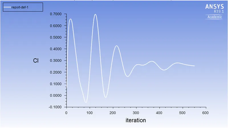
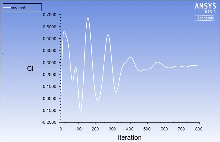
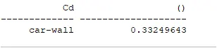
2. The drag coefficient plot for a refined case.
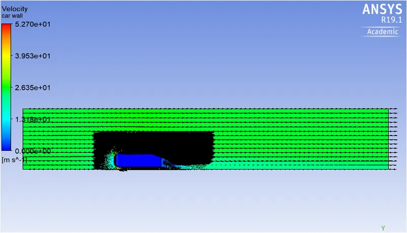
3. The vector plot clearly showing the wake region.
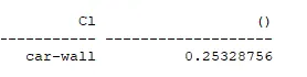
4. Perform the grid independency test and provide the values of drag and lift with each case.
Ahmed body and its significance
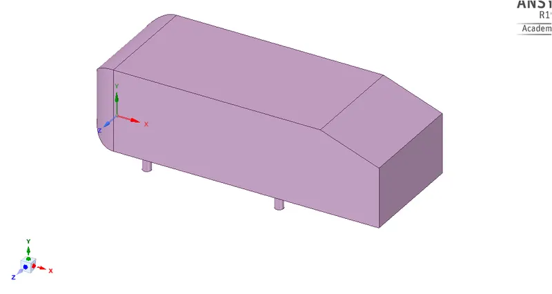
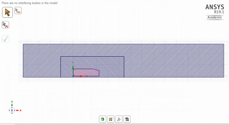
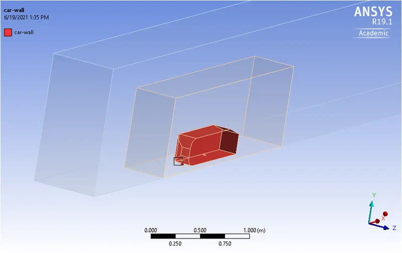
Ahmed body is simplified car model created by S.R. Ahmed in 1980’s to investigate the behaviour of newly developed turbulence models for complex geometry cases. The Ahmed body is made up of a round front part, a movable slant plane placed in the rear of the body to study the separation phenomena at different angles, and a rectangular box, which connects the front and rear slant plane as shown in figure below. The simple geometrical shape has a length of 1.044 meters, height of 0.288 meters, and a width of 0.389 meters. It also has 0.5-meter cylindrical legs attached to the bottom of the body.
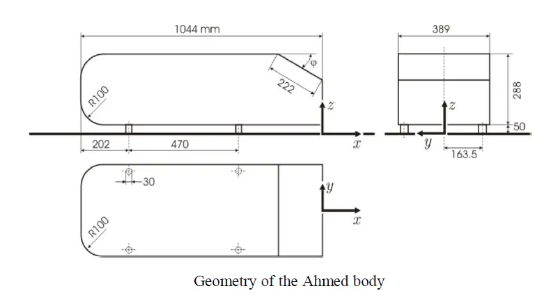
Ahmed body is simplified model of a car body, but it demonstrates all the flow features involved in an actual case of a moving car. Due to the considerable deviation of its geometry from normal vehicles, the body represents the basic aerodynamic properties of a vehicle, especially in the rear part. Its shape is simple enough for accurate simulation and retains some important features with respect to automobile body. This model helps to calculate turbulent flow field around a simple car model.
 .
.
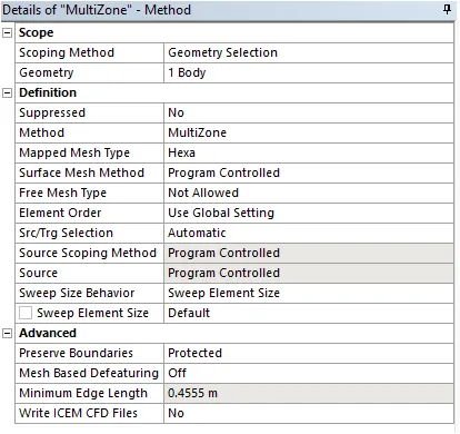
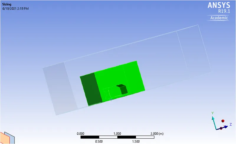
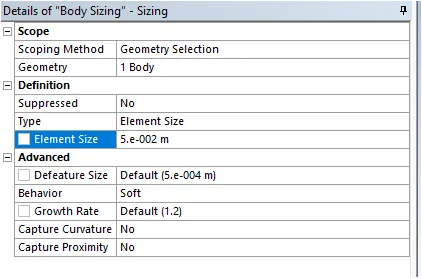
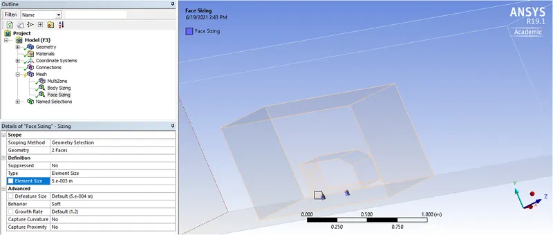
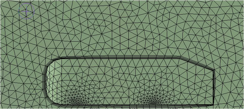
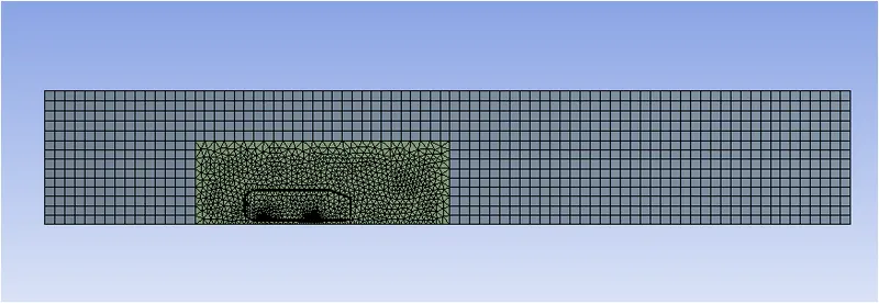
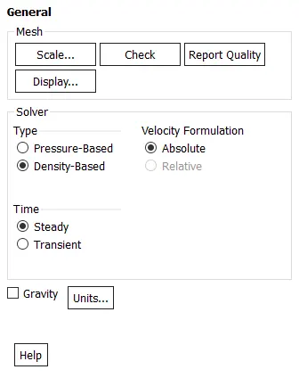
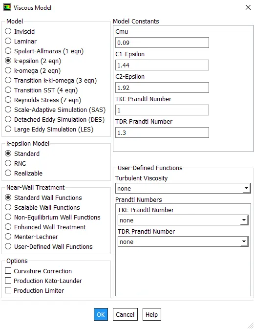
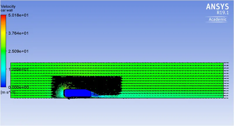
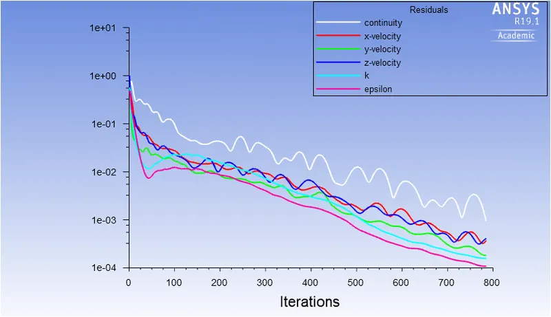
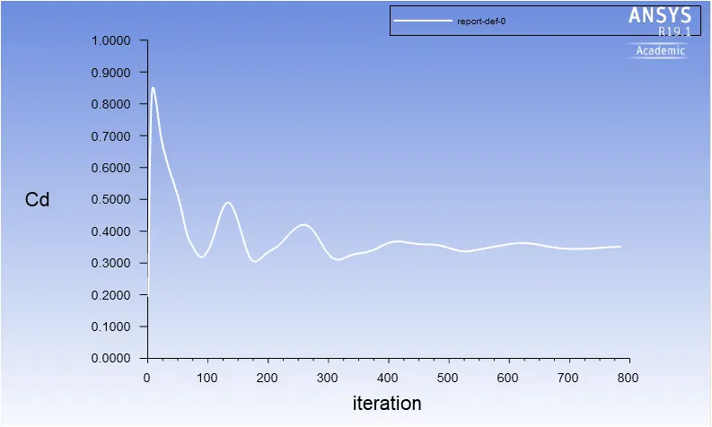
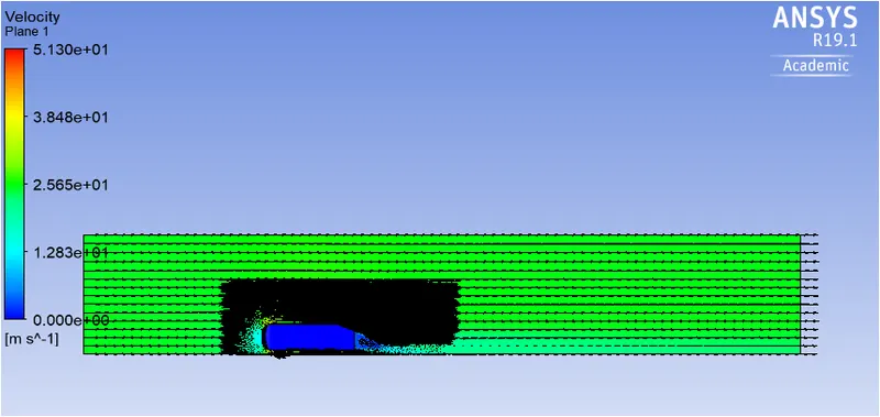
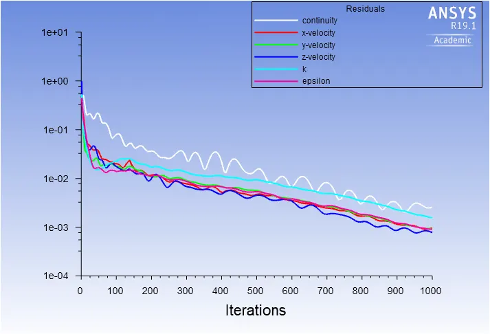
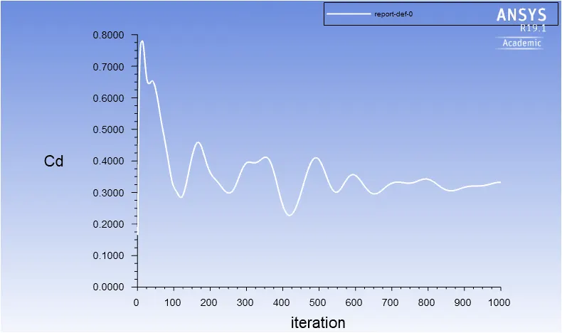
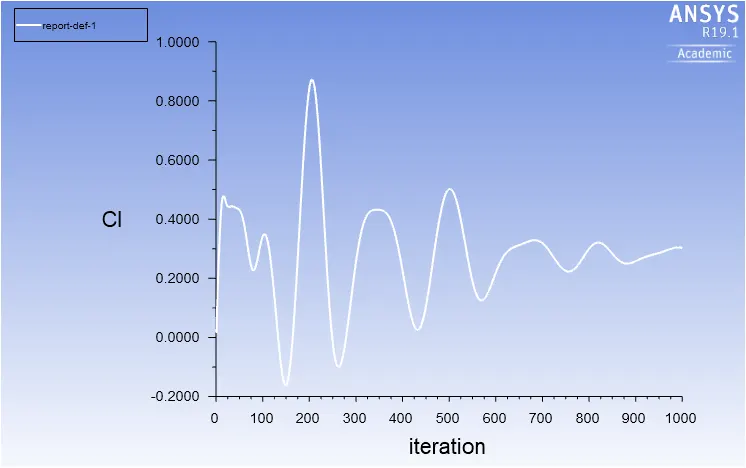
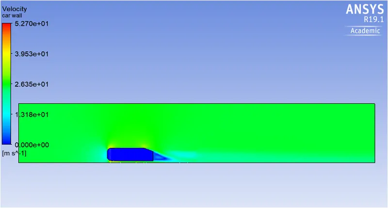
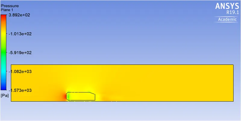
Flow separation is the detachment of a boundary layer from a surface into a wake. Separation occurs in flow that is slowing down, with pressure increasing, after passing the thickest part of a streamline body or passing through a widening passage. During the fluid flow over a body, shear stress caused by viscosity has a retarding effect upon the flow. This effect can however be overcome if there is a negative pressure gradient offered to the flow. A negative pressure gradient is termed a favourable pressure gradient. Such a gradient enables the flow. A positive pressure gradient has the opposite effect and is termed the adverse pressure gradient. Flowing against an increasing pressure is known as flowing in an adverse pressure gradient. The boundary layer separates when it has travelled far enough in an adverse pressure gradient that the speed of the boundary layer relative to the surface has stopped and reversed direction. One of the severe effects of an adverse pressure gradient is to separate the flow. The flow becomes detached from the surface and instead takes the forms of eddies and vortices.
Reason for negative pressure in the wake region
| Sr No | Inner Body Sizing (m) | No of Mesh Elements | Y+ | 1st Layer Thickness (mm) | Cd | Cl |
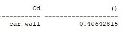
| 1 | 0.05 | 91420 | 200 | 2.92 | 0.4064 | 0.2532 |
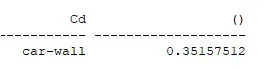
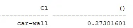
| 2 | 0.035 | 195185 | 100 | 1.46 | 0.3516 | 0.2738 |
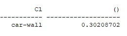
| 3 | 0.025 | 456546 | 50 | 0.73 | 0.3325 | 0.3021 |
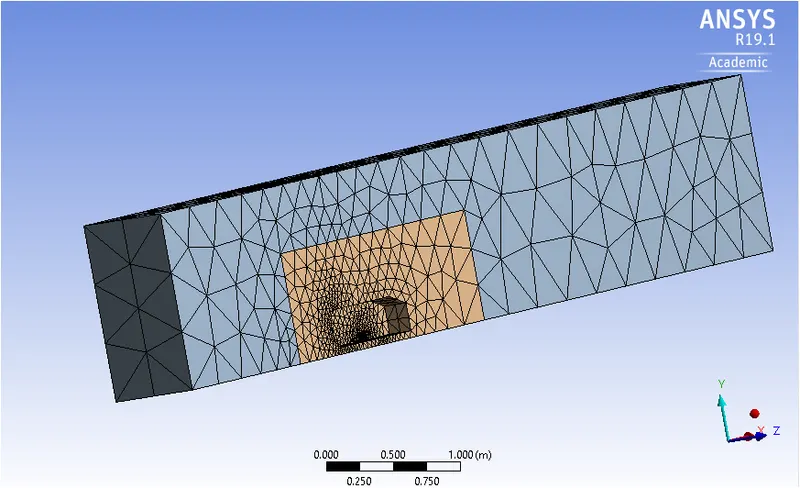
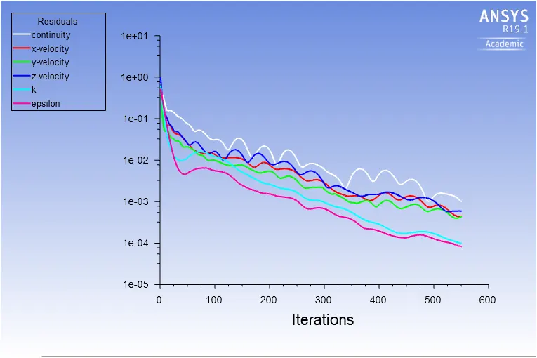
From the above table, it can be seen that the first refinement produces results which are closer to actual value. Only if high accurate results are desired then mesh should be refined further so that computation power and time require for simulation is optimized.
- For this simulation, the results obtained from baseline simulation deviated too much from actual results, hence appropriate mesh refinement was done.
- With increase in number of mesh elements, the value of drag coefficient decreases and reaches closer to actual value.
- Appropriate selection of y+ is important in accurately determing the value of drag coefficient.
- From the mesh independence test, it can be seen that decreasing the size of mesh element and y+ produces the results which are closer to actual value.