Week 3 - External flow simulation over an Ahmed body.
EXTERNAL FLOW SIMULATION OVER AHMED BODY
THEORY (Q1)
Ahmed body is one of the most studied 3D replica of automotive car body. The included angle of ahmed body helps in replicating the actual road vehicles. Ahmed body has been scaled to various sizes and experiments were conducted on it. The experimental data available were compared with numerical simulation and were much similar.
Q2.
- In the wake region flow seperation occurs, due to which flow velocity changes in location at a particular time, which results in pressure changes, this results in negative pressure is the wake region.
Q3.
- At higher reynolds number (turbulent flow) when the flow direction suddenly changes, flow seperation occurs, which can result in reversal of flow direction which results in higher lift and drag forces and creates eddies.
- This eddies needs to be minimised which is greatly dependent on the rear angle of the car body/ahmed body
AIM
- Plot the velocity and pressure contours of ahmed body
- Drag co-efficient of Ahmed Body
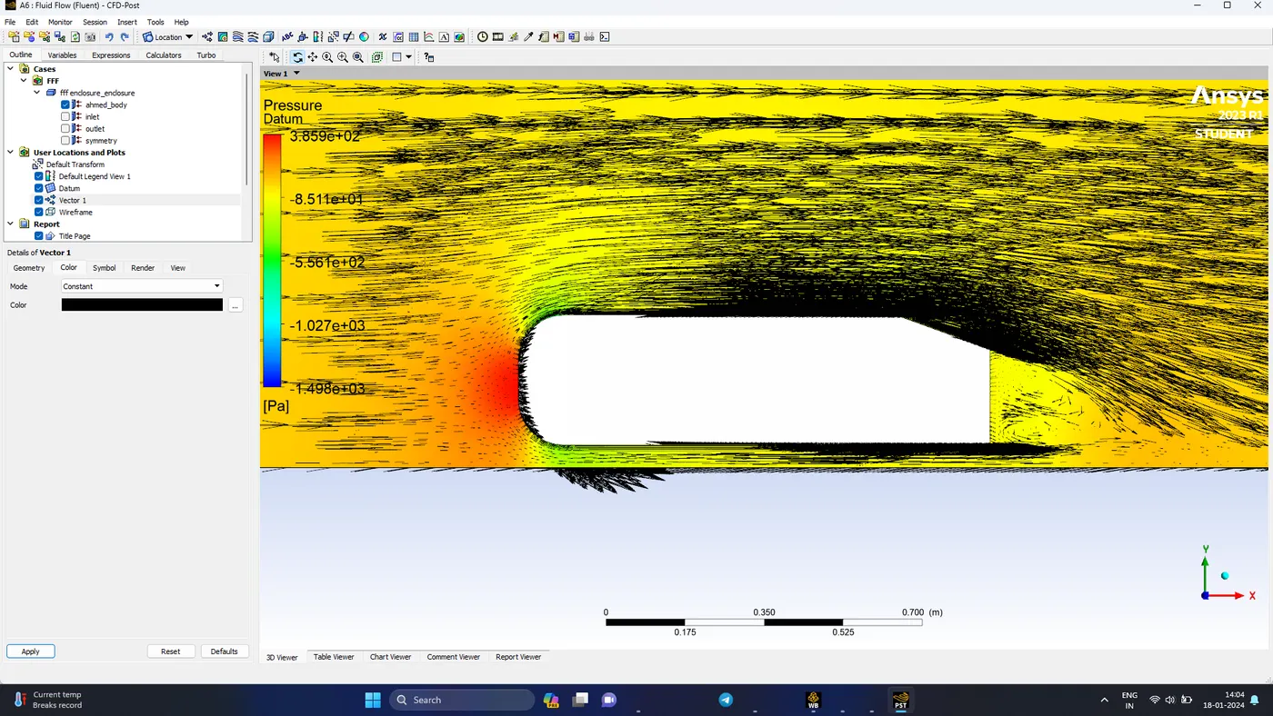
- Vector plot showing the wake region
- Perform grid independency test and provide the values of drag and lift of different cases
PROCEDURE
- Add Fluid flow (fluent) in the workbench and start SpaceClaim
SpaceClaim
- Import the provided geometry of Ahmed Body
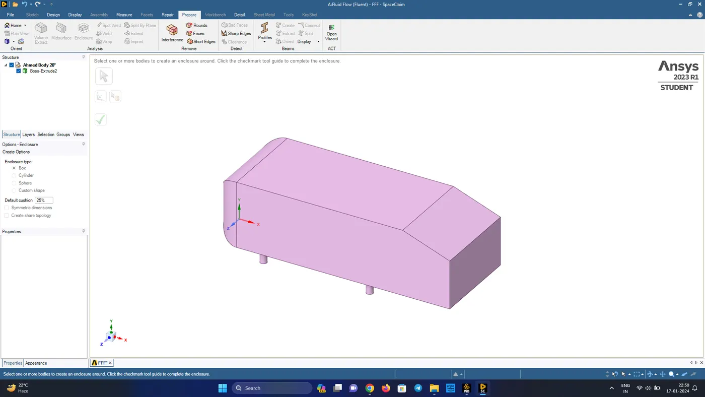
- In prepare tab choose the enclosure tab and click on the Ahmed body
- Un-tick the symmetry dimension option and generate the enclosure with the following dimension from each side
| Region | Dimension |
| Front | 2m |
| Back | 5m |
| Top | 1m |
| Sides | 0.5m |
| Bottom | 0m |
- Click on the green tick on the left side of window to generate the enclosure
- To refine the mesh near the Ahmed body walls, we create a new enclosure of the following dimensions
| Region | Dimension |
| Front | 0.5 m |
| Back | 1 m |
| Top | 0.5 m |
| Sides | 0.26 m |
| Bottom | 0 m |
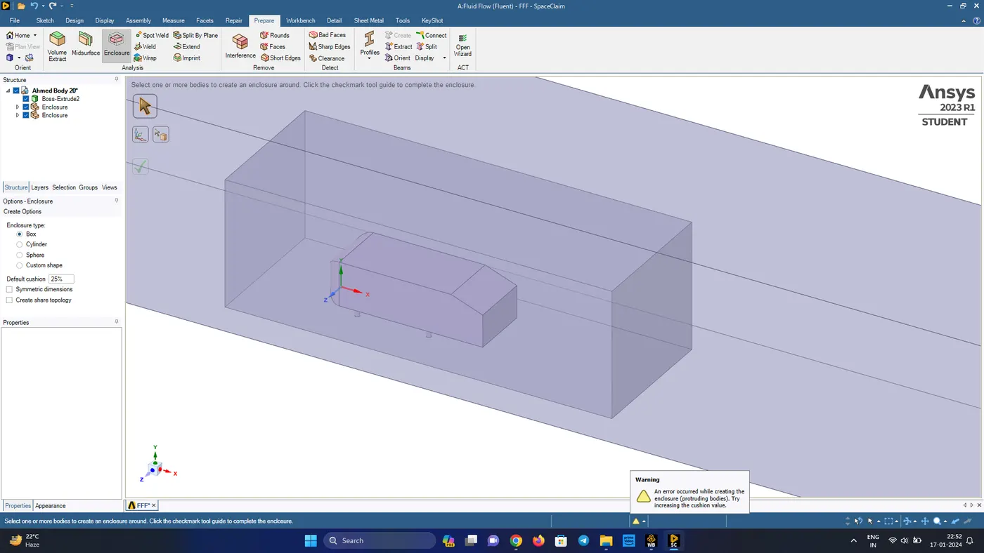
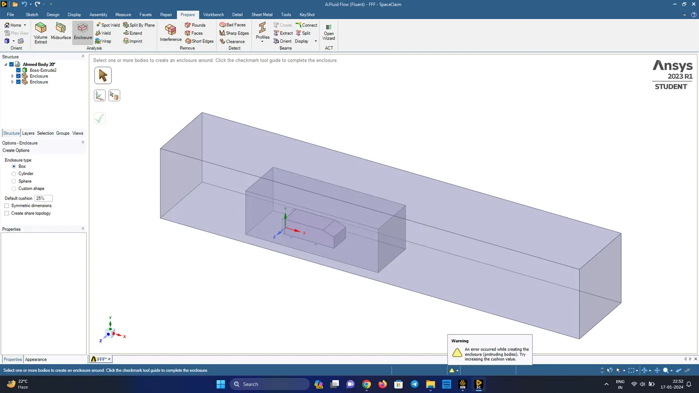
- Next hide the initial ahmed body and supress it for physics
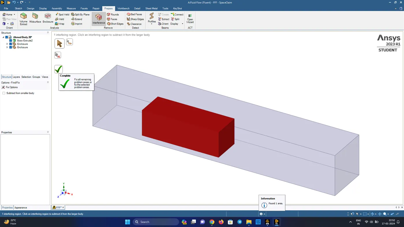
- In prepare, check for interference and click the tick mark to eliminate the interference error
- Create a plane on XY plane in the middle and split the body into half and also check for any interference error
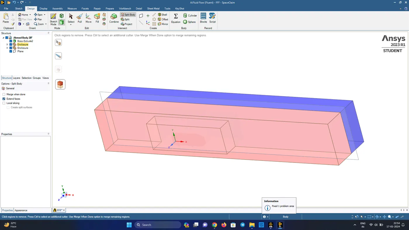
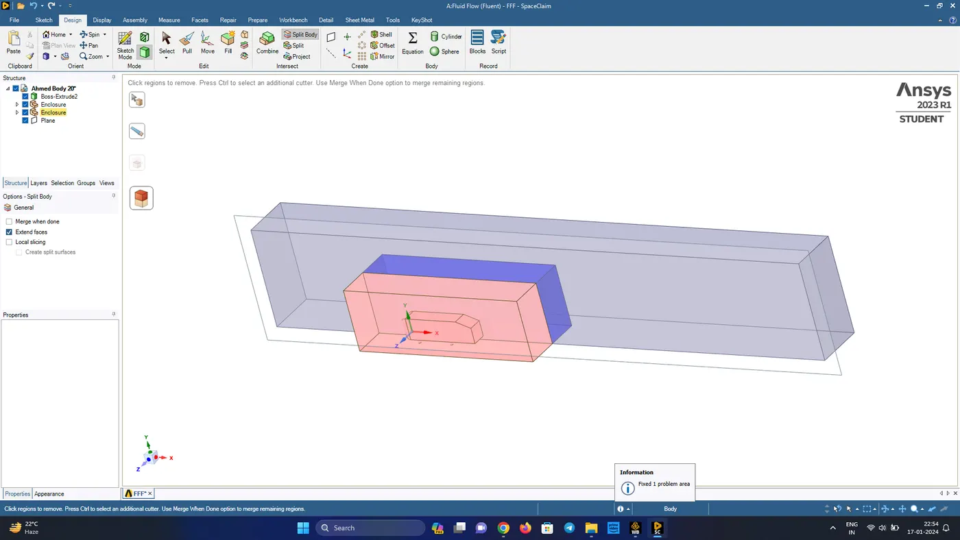
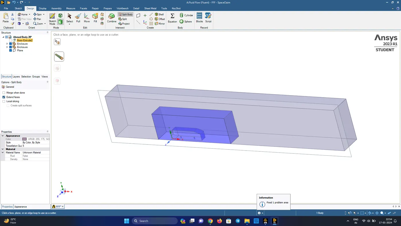
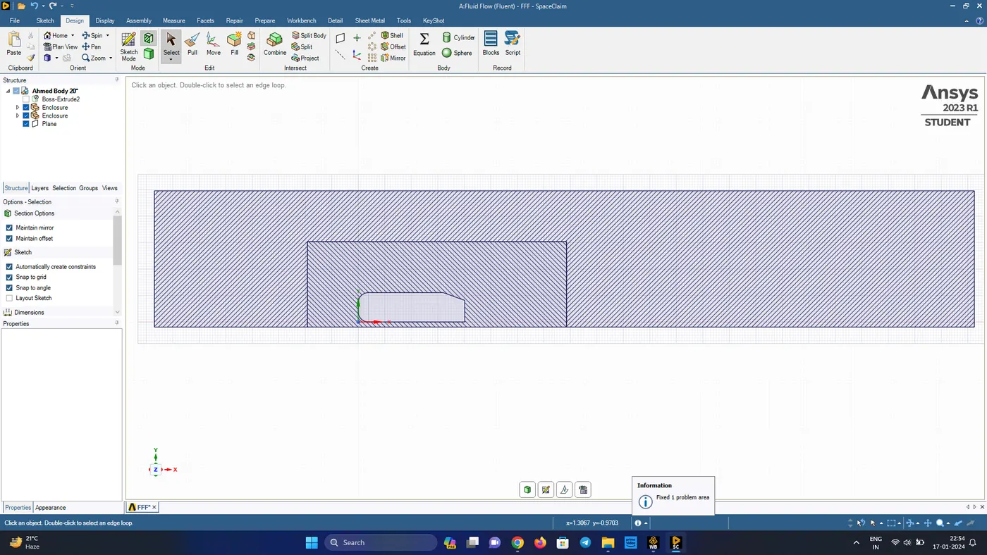
- In the workbench click the share option to share the faces among the two enclosures and click okay
- Open Meshing
Meshing
- check the mesh quality and then start the face naming
- Name the inlet, outlet and Ahmed body (by hiding outer faces with F8 key and using the box selection) and the remaining side faces, bottom face as symmetry
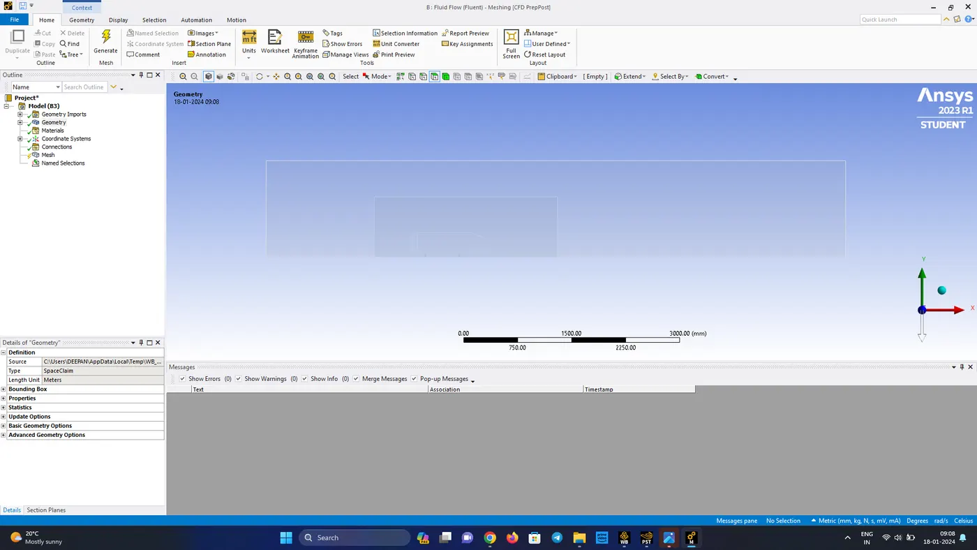
- After named selections, click on the mesh ----> generate mesh for generating the basic mesh
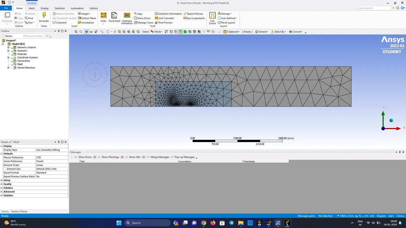
- For larger areas it is better to have quadlateral mesh elements for better results and easy of computation
- In mesh method select the outer body and click apply in geometry selection and choose multizone in method and then press the mesh button and then change the element size to 100mm and in the sizing change the maximum element size to 100mm
- click on generate mesh
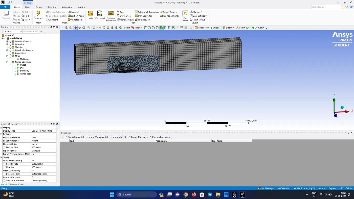
- In the mesh select sizing ----> select the inner enclosure and give the mesh size to be 50mm and generate the mesh
- Then again insert mesh sizing and select the ahmed body and give the mesh size as 20mm and click on generate mesh
- For the final change add inflation of 5 layers for the ahmed body for a body fitted mesh
- Give the total thickness as 12.5mm and generate the inflation layer
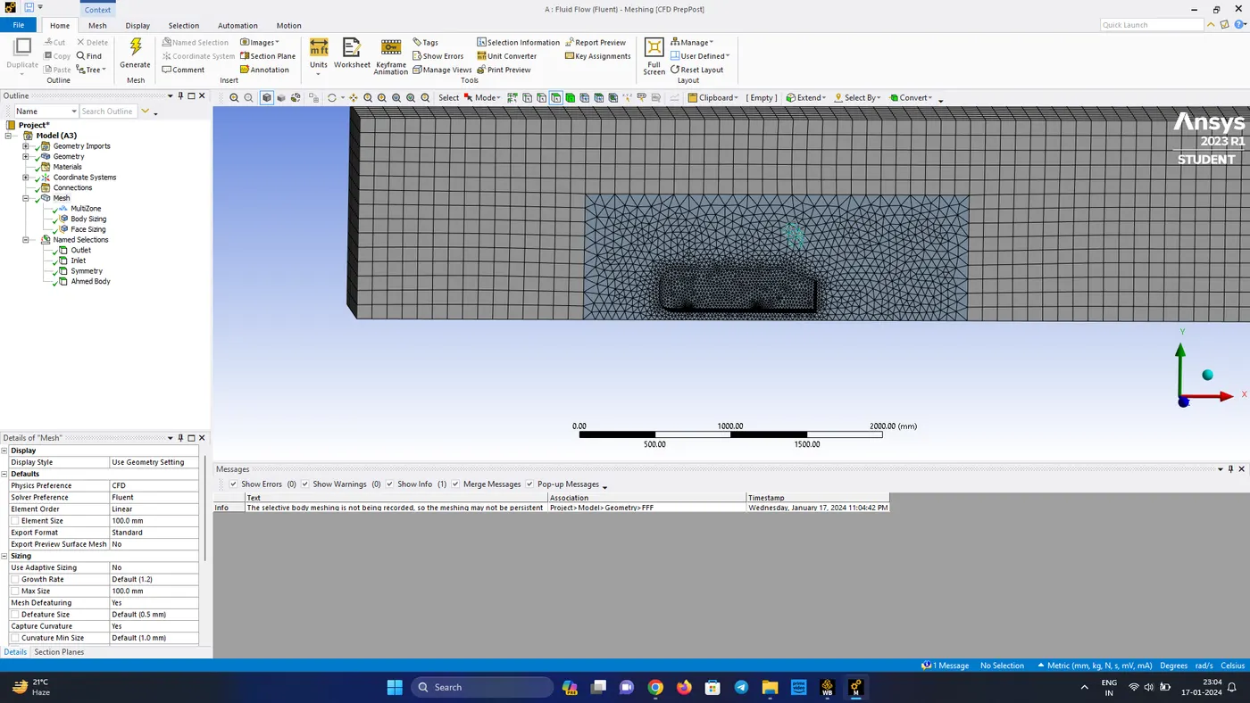
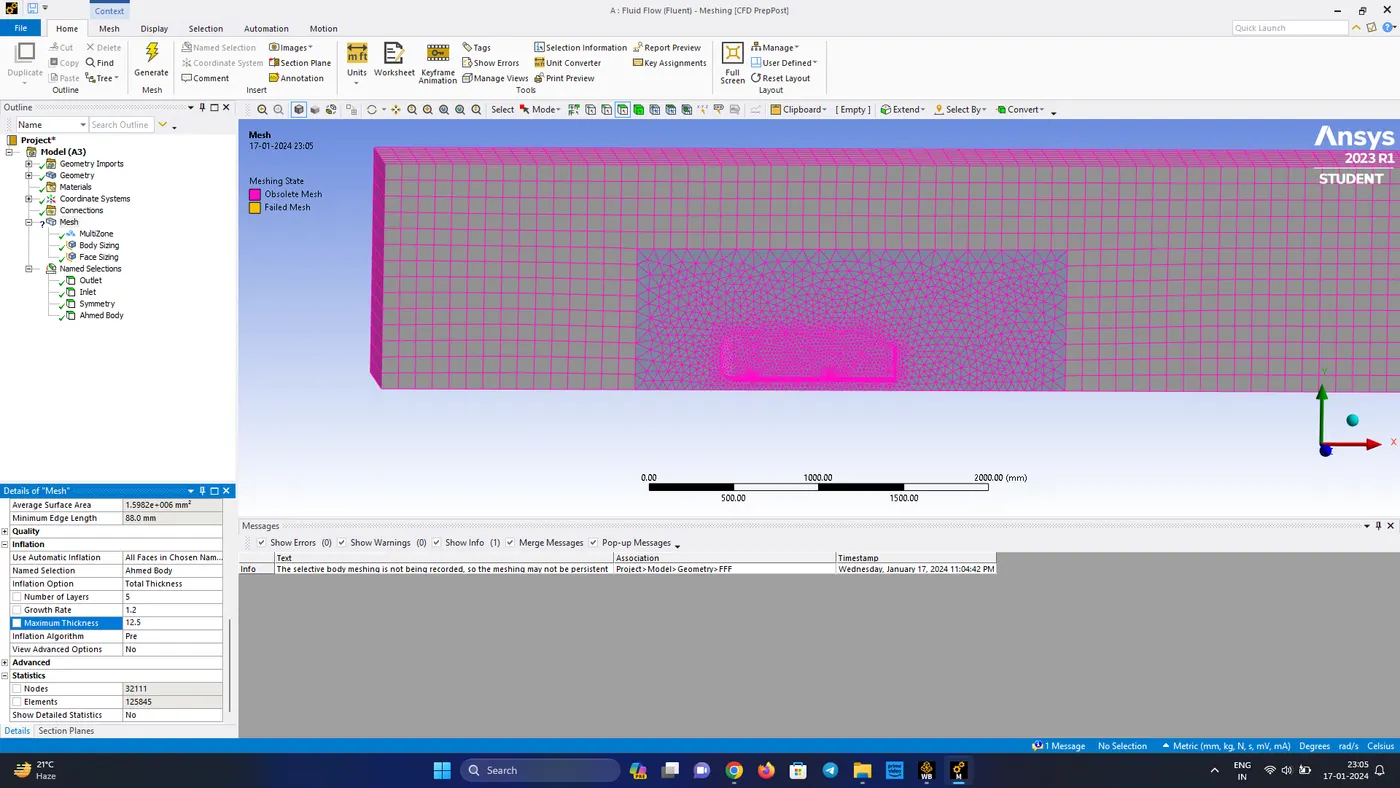
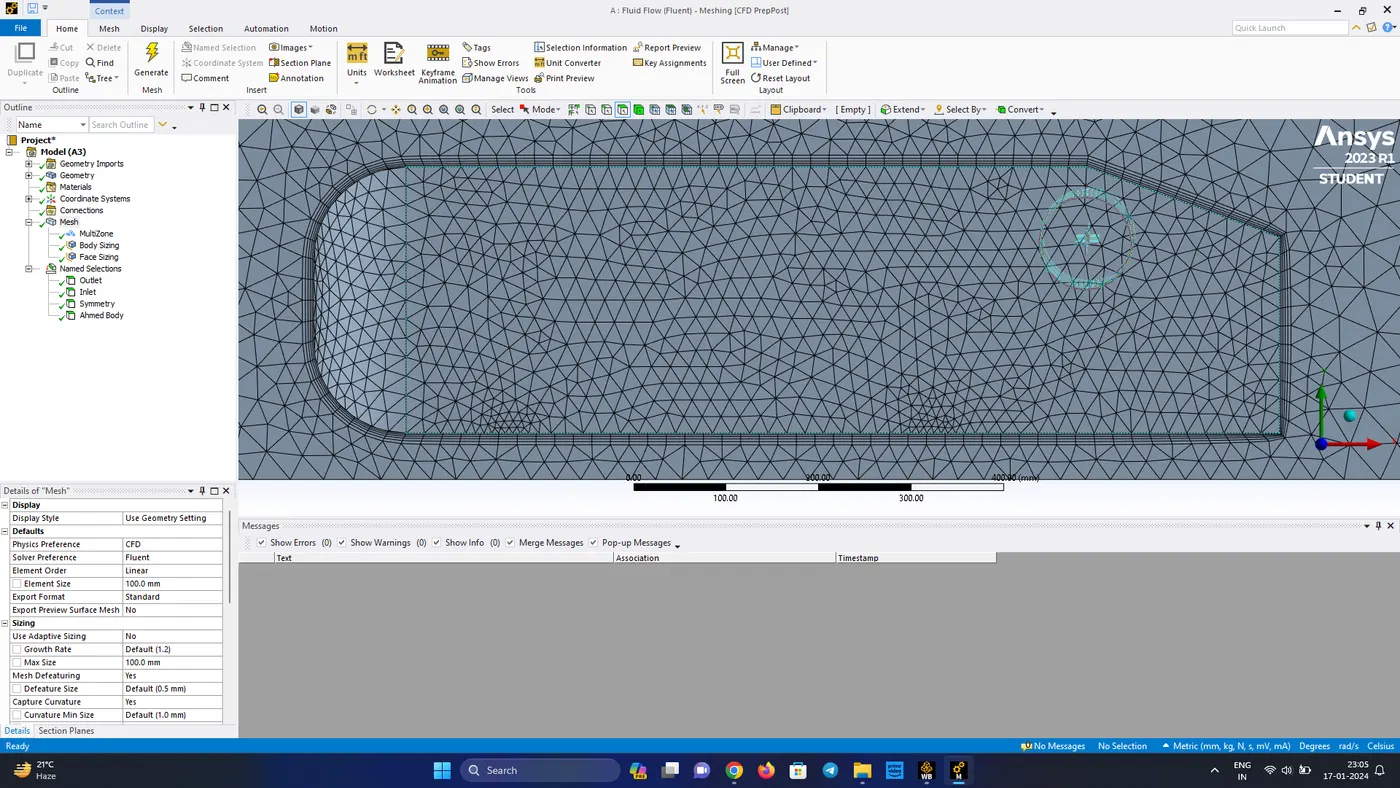
Total mesh elements for the generated mesh is as follows:
| Nodes | 43618 |
| Elements | 135840 |
- Close the meshing interface and go to the workbench and select setup to open Ansys Fluent turn on double precision and include 4 solver
Ansys Fluent
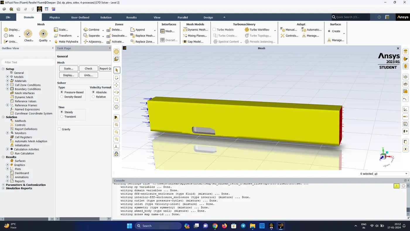
- Firstly check the mesh quality and perform the mesh check
Mesh Quality
Minimum Orthogonal Quality : 1.258e-1
Maximum Aspect Ratio : 5.653e+1
- Next check whether all the parts have been successfully loaded
- Since the analysis has a Mach No. of 0.073 it is safe to take pressure-based solver (here we have taken density based solver)
- In the physics, add k-epsilon with 2 equation and ensure to check mark the energy criteria
- Check the material make sure air is loaded and then click the cell zones and make sure the material selected is air
- In the next step check the boundary conditions
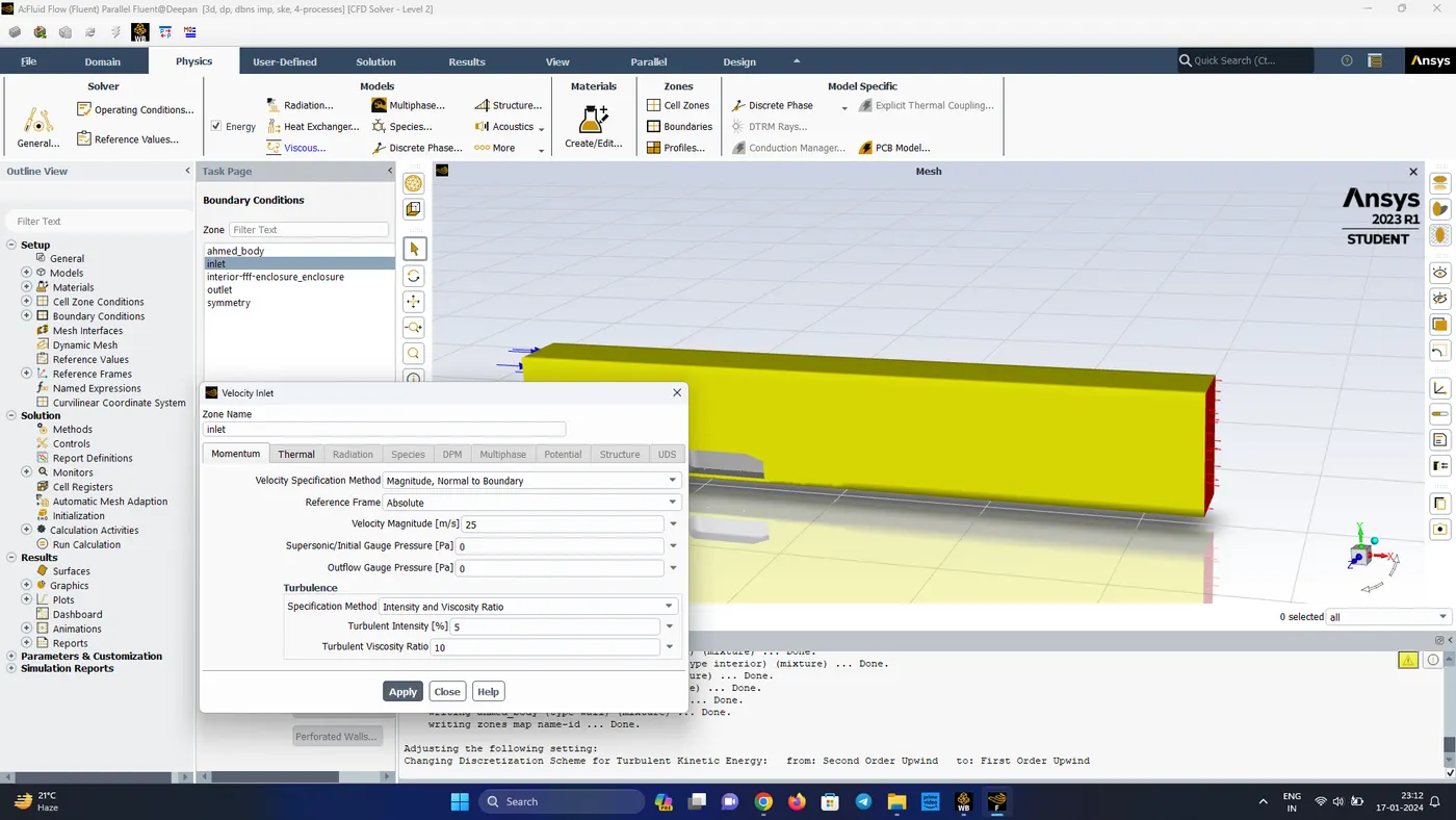
- Inlet boundary condition should be velocity-inlet condition
- The inlet air velocity is changed to 25 m/s and temperature to be 300 K
- Symmetry walls should be symmetery boundary condition
- Outlet should be pressure-outlet with 0 guage pressure
- In the definitions add drag force co-efficient in the forces section
- Initialize the problem and the in the post-processing create a plane and add pressure and velocity contours also add solution animation for velocity contours for every 20 iterations
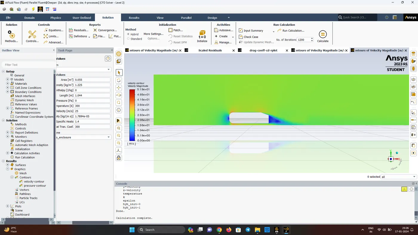
- The velocity contour clearly shows the wake region (flow seperation) happening in the rear end of the ahmed body
- We can see where the air impacts the body, the velocity is zero and where the crossectional area changes, the velocity in increases to maximum, this difference in velocity leads to a flow seperation, which gets predominant in the rear end
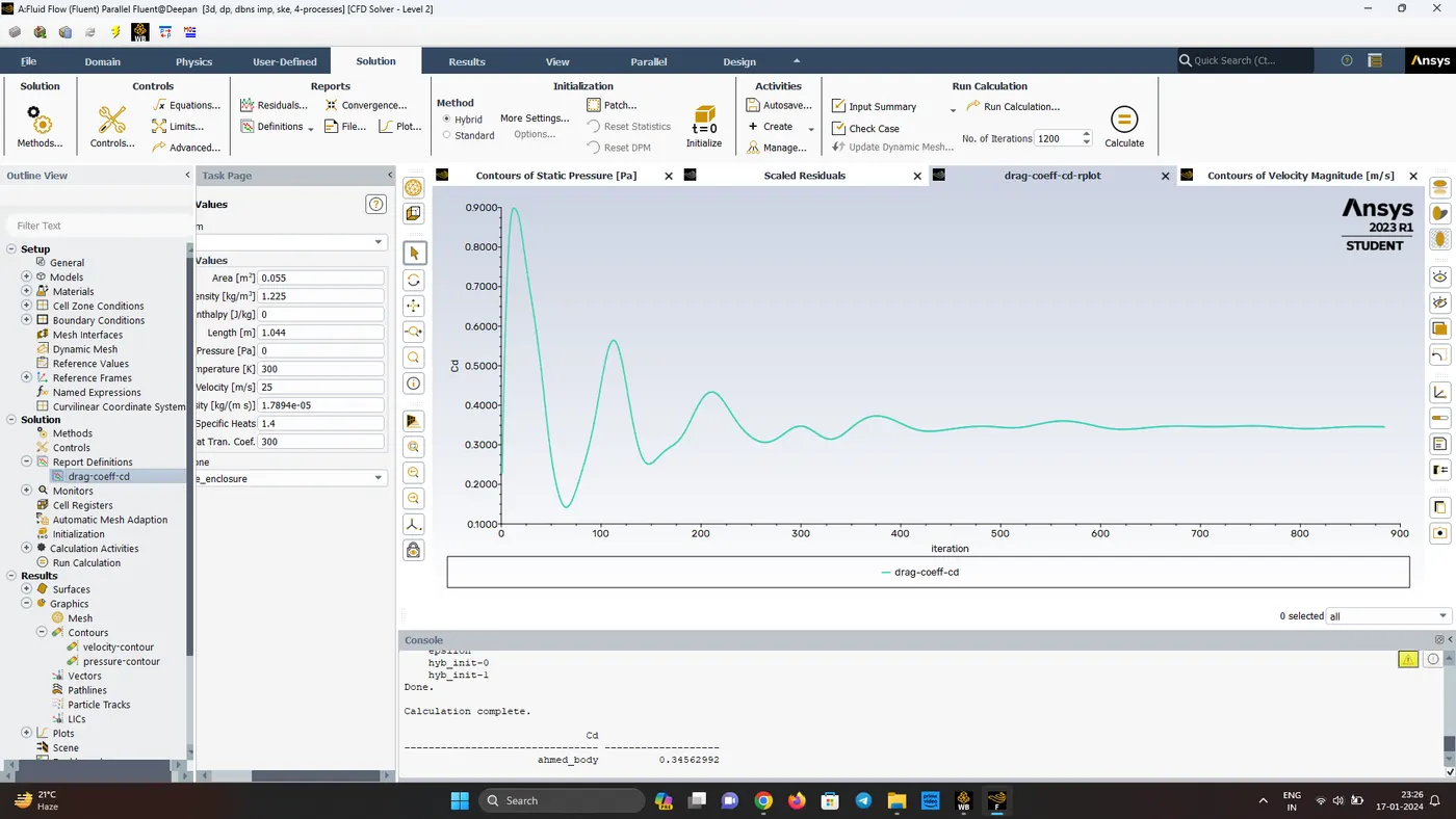
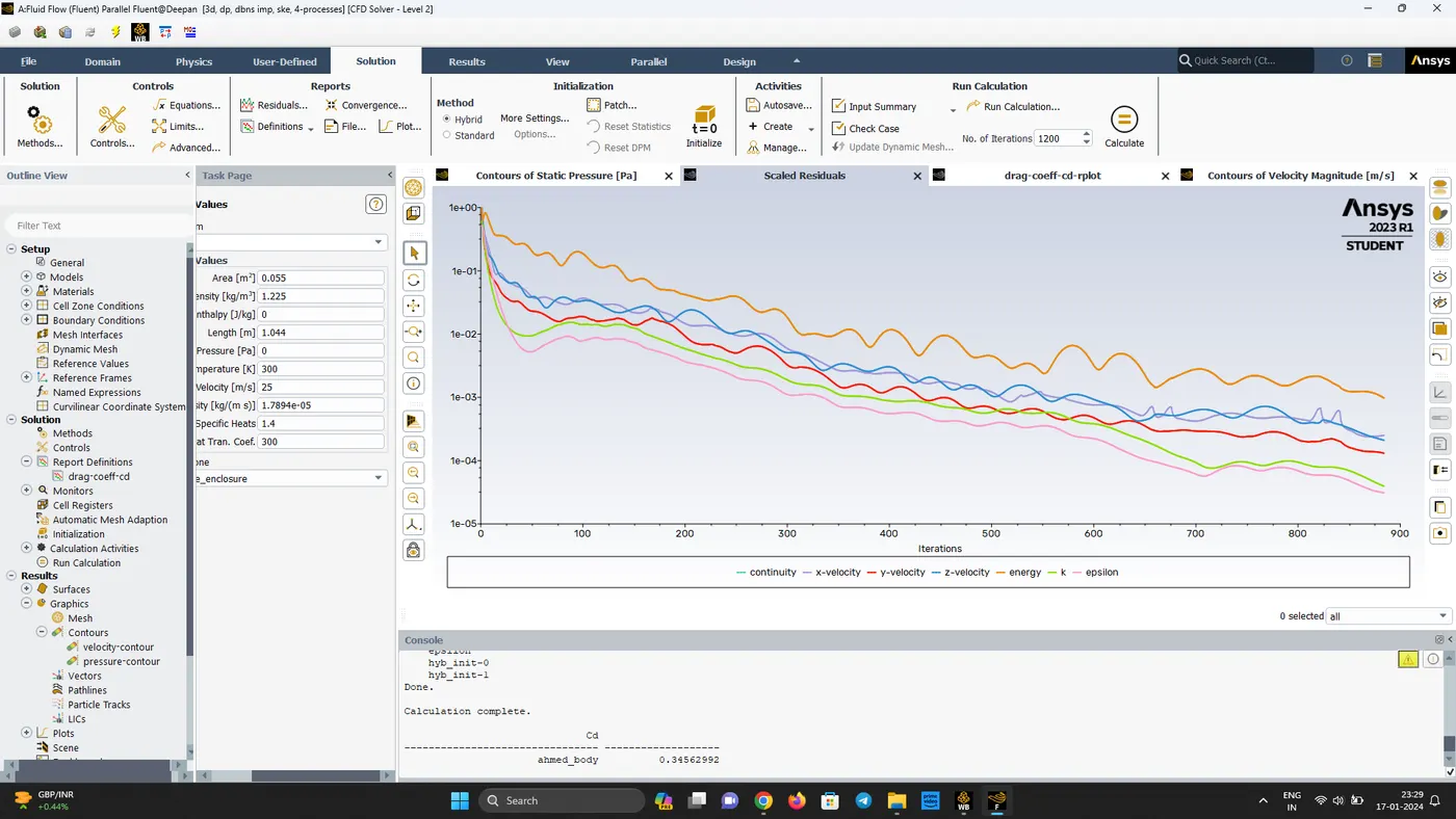
- As the flow achieves convergence, the drag co-efficient is Cd= 0.345, which is very much close to the reasearch paper value of 0.33
- This difference of 4.5% in Cd value may be due to mesh refinement
- Close Ansys Fluent and open the results from workbench to start CFD post-processing
- In the insert create a plane near the wheel region and in appearance give variable and colour it to velocity
- Here we can clearly see the wake region developing in front. back and behind the wheels
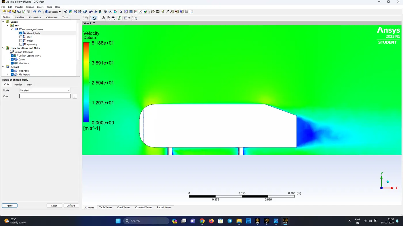
- The wake region can much clearly be understood by the negative pressure created arounf the flow field due to flow seperation
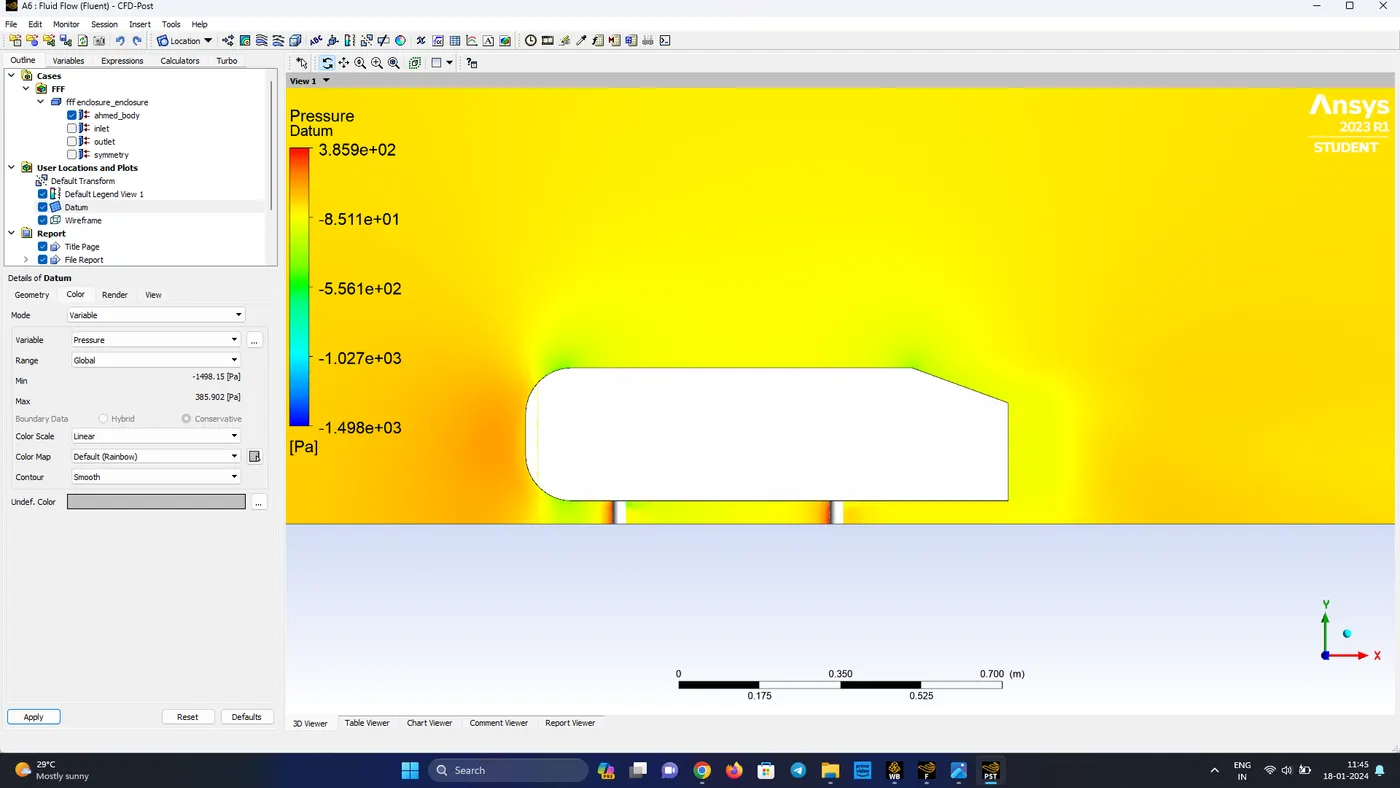
- The x-velocity plot (u-velocity) in CFD post-processing clearly shows the wake region in the rear side of the ahmed body
| Mesh Statistics | Drag Co-efficient (Cd) | Lift Co-efficient (Cl) |
| Nodes: 43618 | 0.345 | 0.304 |
| Elements: 135840 | ||
| Nodes: 64285 | 0.333 | 0.304 |
| Elements: 222858 |
CONCLUSIONS
- Ahmed body helps in predicting the various parameters for an automobile design
- With a higher degree of refinement around the wake region the results obtained are much more refined
- When the refinement is increased, the drag co-efficient has reached a value same as that of the research paper readings
- The vector plots helps in clearly identifying the wake region
- Due to flow seperation negative pressure regions are formed which results in lift and drag forces acting on the flow around ahmed body