Week 1- Mixing Tee
ANSYS FLUENT-CHALLENGE 1
AIM
- To conduct a CFD simulation of air-mixing inside a Mixing Tee
INTRODUCTION
- Air is passed through a mixing tee with two inlets and one outlet
- The mixing tees are of diffeent length
- The air inlet velocity is changed in two cases
- The effect of mixing tee lengths and velocity ratios needs to be studied
THEORY
- These are simple structures used in industries for mixing of subtances (mostly liquids)
- The mixing can be for thermal gains or chemical mixing
- The application can be seen in Automobiles, petrochemical industries etc.
- In HVAC we can see its use in mixing fresh air with the re-circulated air
- In Petroleum industries, they are used to infuse chemicals and steams into pipelines for various processes
CASE 1
- In the first case we take the short mixing-tee
- The hot inlet in x-direction is at a temperature of `36^o`C and a velocity of 3 m/s and Cold inlet in y-direction is of `19^o` C and 6 m/s (momentum ratio 2)
Length : 192.37 mm
Diameter : 33.87 mm
- The working domain is chooses as Fluid Flow (Fluent) as it captures the fluid flow analysis the best
- Then for geometry editing, we use SpaceClaim
- We capture volume of fluid interations using volume extract tool and with the help of edge selection
- Then we supress the shell physics from the analysis
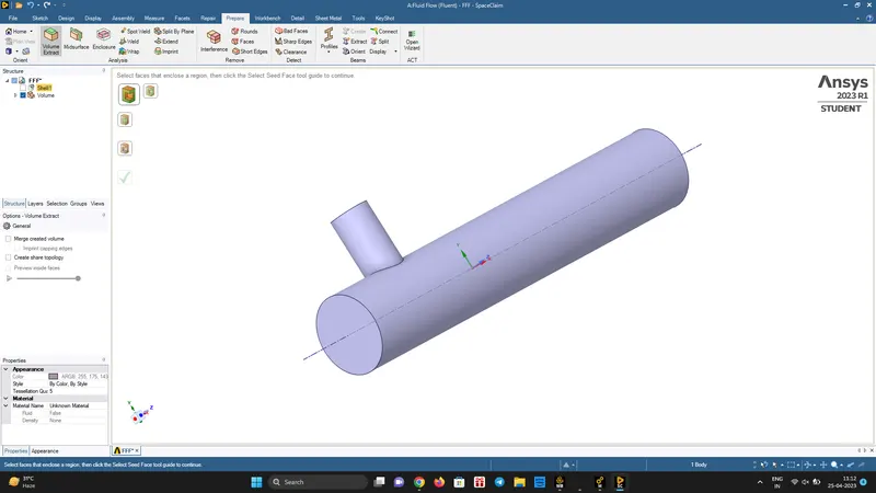
- The next step we close the SpaceClaim and we go to the mesh tool
- In mesh we go for a mesh size of 2.5mm
- To check the mesh, we use section plane, we click and drag to cut the geometry to have a check on the meshes
- To generate the mesh, click generate
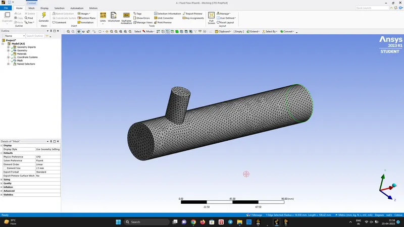
Nodes: 12580
Elements: 61186
- Then we click update mesh to use the meshed geometry for further analysis
- Add names to different faces so as to give Boundary conditions to the faces
- With this we have completed the Pre-Processing
Solution
- In the Workbench we then go for the solution, which launches the Fluent
- Turn on the double precesion and start with 4-processor
- Firstly we check for the mesh
- Then we select pressure based solver (Mach No < 0.3, so incompressible fluid fow), absolute velocity formulation and Steady State analysis
- In the physics we select energy as temperature is an input for the analysis
- In the Viscous-Turbulent Model, we select k-epsilon(2-eq) model
- Add air as the material
- In the cell zones add air as the volume region
- And the next step is to add Boundary conditions
- Give the necessary Boundary conditions to both the inlet
- In Solution ----> Definitions (Report tab) ---> New ----> Surface Report ----> Area Weighted Average and Standard Deviation and apply it
- Initialize and then give 350 iterations and give calculate
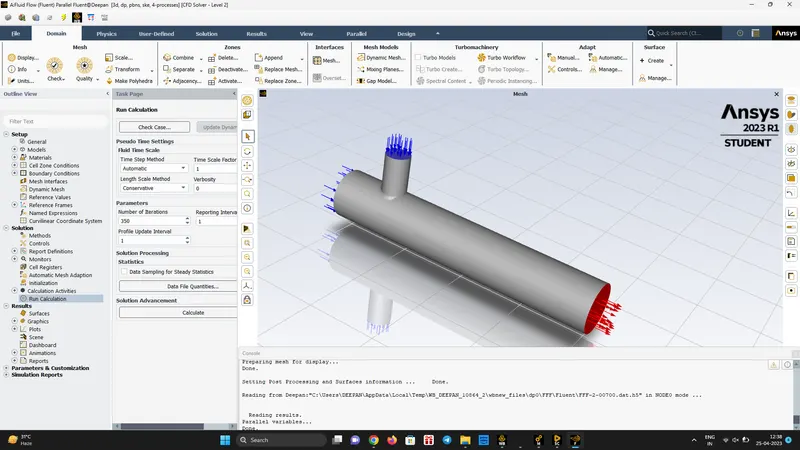
- The solution stage is now completed
- The residuals obtaines, we need to make sure stead-state is achieved or not, continue the iteration till staedy-state is achieved
- If solution hasnt attained convergence, we should increase the iterations
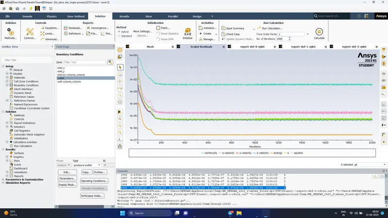
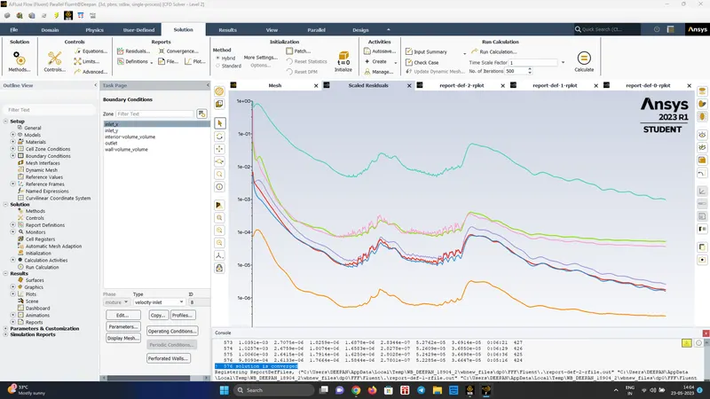
Residuals
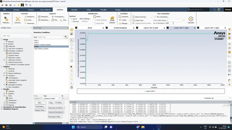
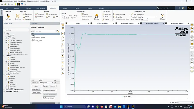
Area-Weighted Average of Velocity magnitude at Outlet
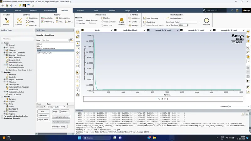
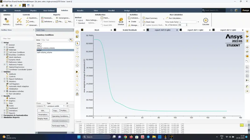
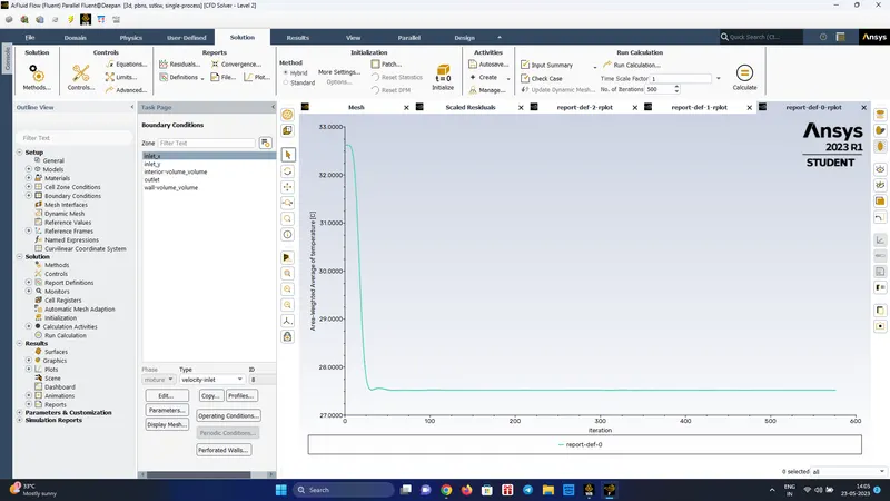
Area-Weighted Average Temperature at outlet
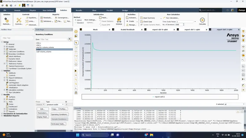
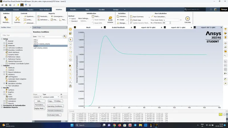
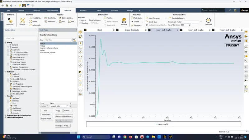
Standard Deviation of temperature at Outlet
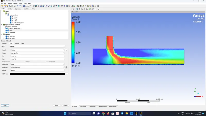
Post-Processing (Momentum Ratio 2)
- X-Inlet Velocity = 3 m/s
- Y-Inlet Velocity = 6 m/s
- First we increase the transparency of the body in the results/post-processing
- Then we insert a plane in xy-plane with z=0
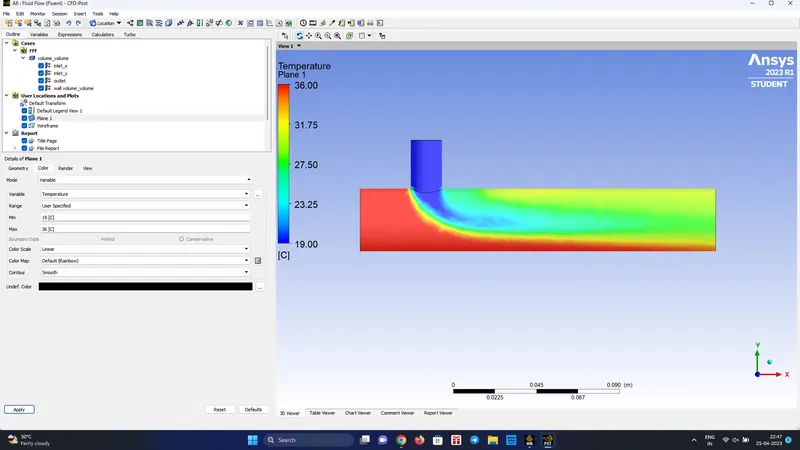
- In colors we give the colour as variable temperature and we get the temperature distribution in the plane created
- Solution is not converged even in 550th iteration
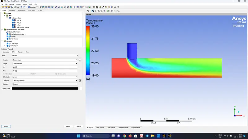
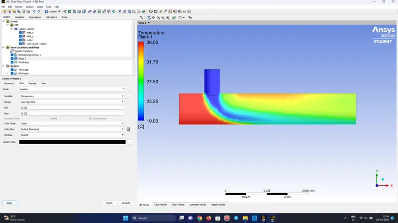
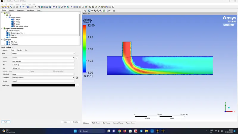
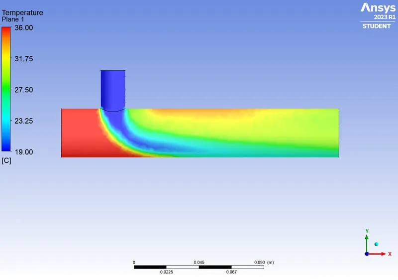
Post-Processing (Velocity Ratio 4)
- X-Inlet Velocity = 3 m/s
- Y-Inlet Velocity = 12 m/s
- Attained convergence in 175th iteration
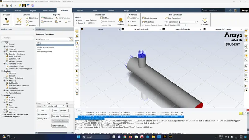
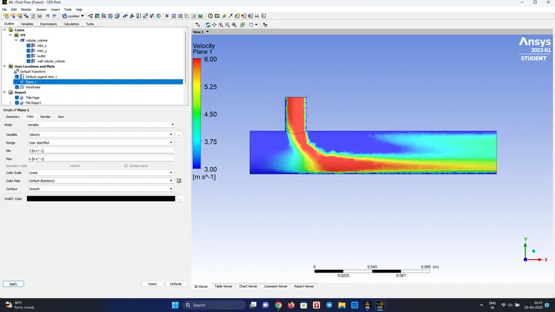
Post Processing - k-omega (2 eq) || VR = 2
- Here the solution has attained convergence in 258th iteration
- In k-omega model the solver stops the iteration once the convergence criteria is attained and the convergence criteria is found to achieve at a faster rate
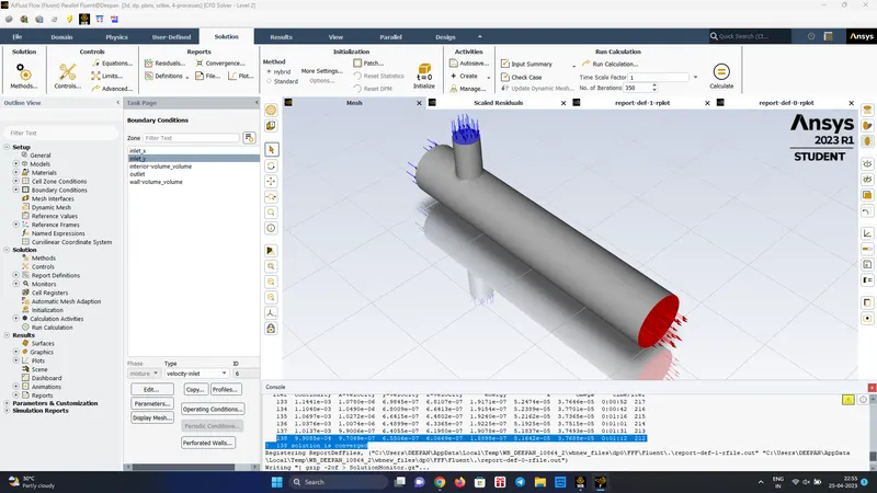
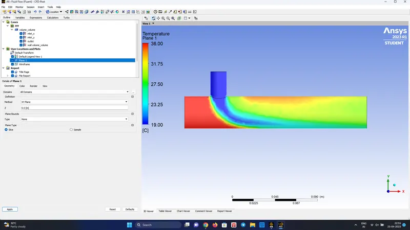
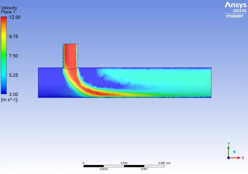
Post Processing - k-omega (2 eq) || VR = 4
- X-Inlet Velocity = 3 m/s
- Y-Inlet Velocity = 12 m/s
- The solution is converged in 138th iteration
- Steady state is attained at a faster rate when the velocity ratio is increased
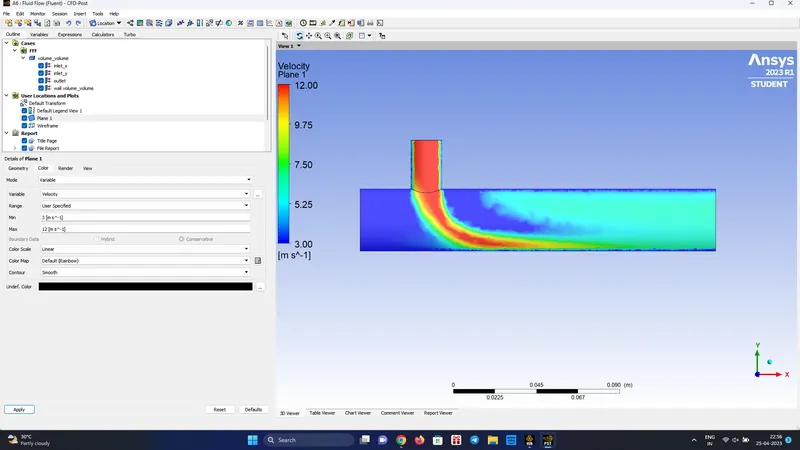
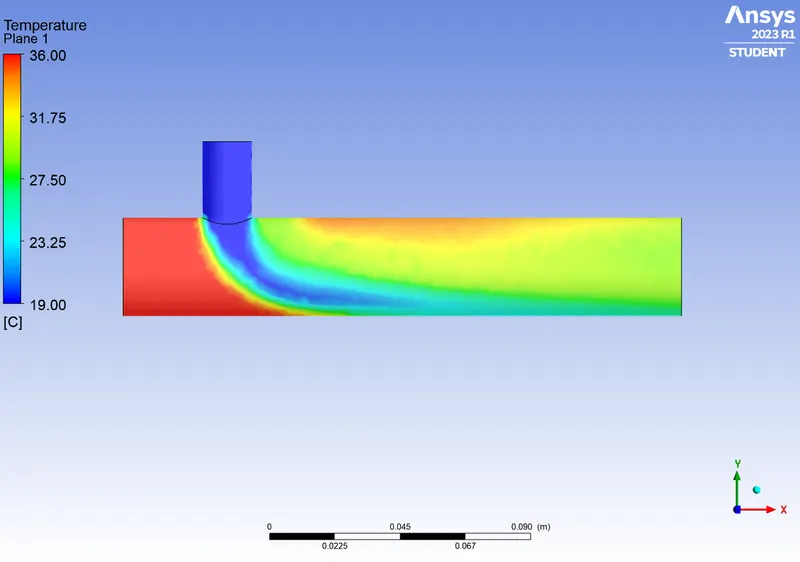
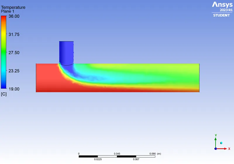
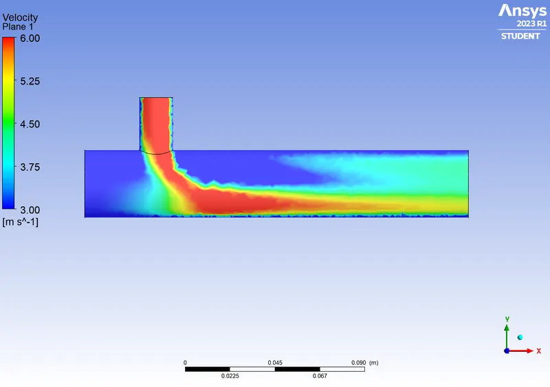
Comparison of k-epsilon and k-omega with different velocity ratio for short mixing-tee
| VR | k-epsilon || Velocity | k-epsilon || Temperature | k-omega || Velocity | k-omega || Temperature |
| 4 | 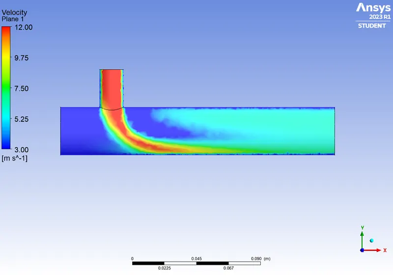 |
 |
 |
 |
| Converged at 175th iteration | Converged at 138th iteration | |||
| 2 | 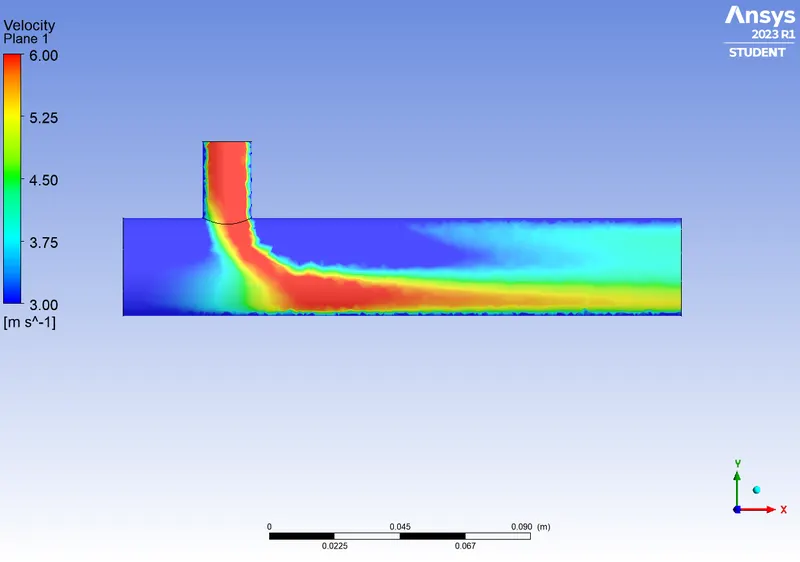 |
 |
 |
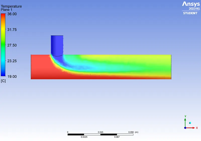 |
| No Convergence at 2000th iteration | Converged at 258th iteration |
COMPARISON
- As we increase the velocity ratio, solution gets converged faster
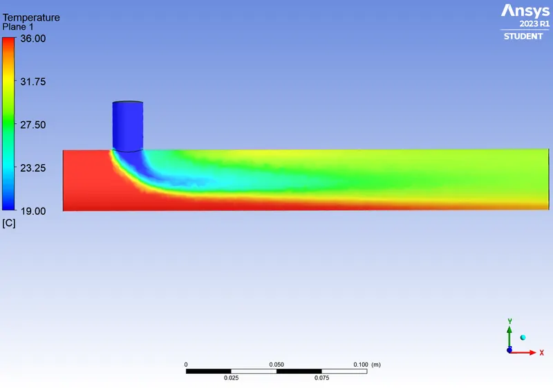
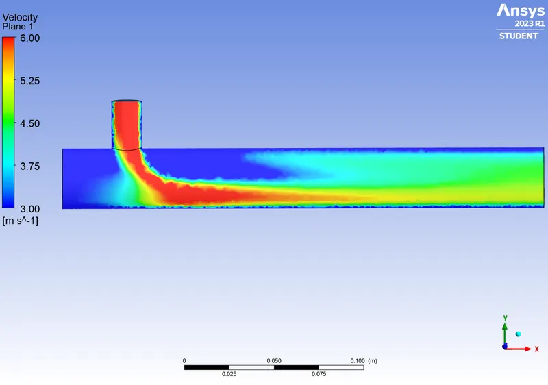
- As the VR is increased, the magnitude of temperature and velocity has been more uniform
- As we compary k-epsilon and k-omega, the solution is attained at a faster rate, 175th iteration to 138th iteration for a velocity ratio of 4
- From this, it cam be concluded that for the particular flow condition, k-omega model helps in better solution at a faster computational time
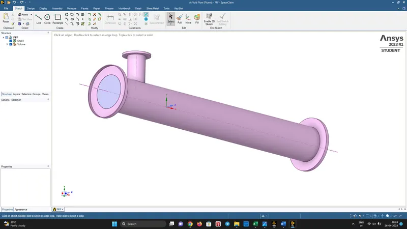
Case 2 - Long Mixing Tee
Length : 268.33 mm
Diameter : 33.87 mm
Volume Extraction - SpaceClaim
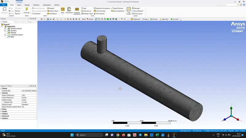
Meshing
Mesh Size : 2.5 mm
Nodes : 17624
Elements : 86711
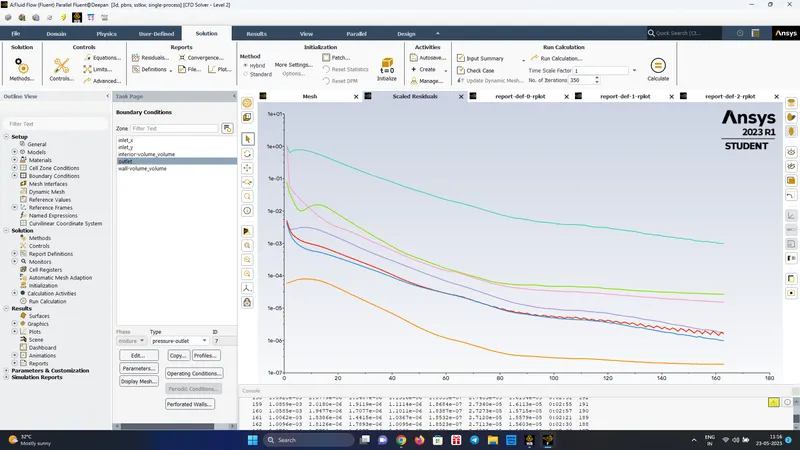
Solution || VR=2
- The solution is converged at 163rd iteration
Post Processing - k-omega (2 eq) || VR = 2
- X-Inlet Velocity = 3 m/s
- Y-Inlet Velocity = 6 m/s
- The solution is converged in 163rd iteration
- As the lenth of the pipe is increased, the solution attained convergence earlier from 258th iteration to 163rd iteration
Temperature Distribution
Velocity Distribution
Solution || VR=4
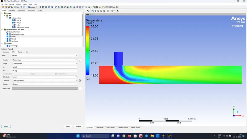
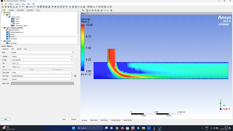
- The solution attained convergence at 575th iteration
Post Processing - k-omega (2 eq) || VR = 4
- X-Inlet Velocity = 3 m/s
- Y-Inlet Velocity = 12 m/s
- The solution is converged in 575th iteration
- As the lenth of the pipe is increased, the solution attained convergence later due to the increase in temperature
Temperature
Velocity
Conclusion
- As we inclease the length of the pipe, the solution attained convergence at 163rd iteration for VR 2
- For VR of 4, the solution required more iterations and the solution attained convergence at 575th iteration, this may be due to more turbulence set by the higher velocity ratio
- In short the solution is greatly affected by the pipe length and velocity ratio