Week 3 - External flow simulation over an Ahmed body.
Q1. Describe Ahmed's body and its importance.
Answer:
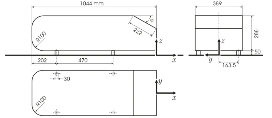
The Ahmed body is a simplified car model widely used in aerodynamic studies and benchmarking. It was introduced by Professor Ahmed in the 1980s and is characterised by its simplified geometry, representing a generic car shape with a slanted rear end. This model is precious in computational analysis and wind tunnel testing to understand the aerodynamic characteristics of vehicles.
The importance of the Ahmed body in computational analysis lies in its ability to provide insights into the aerodynamic forces acting on a vehicle, such as drag and lift. Researchers and engineers use CFD simulations with the Ahmed body to optimise vehicle design for improved fuel efficiency, stability, and overall performance. Understanding the flow patterns around the Ahmed body helps shape more aerodynamically efficient cars, reducing fuel consumption and enhancing handling.
----XXX----XXX----XXX----
Q2. Explain the reason for the negative pressure in the wake region.
Answer:
The negative pressure (or low pressure) in the wake region of a car model is primarily a result of aerodynamic forces and the flow patterns around the vehicle. The wake is the turbulent flow region that forms behind a moving object, such as a car, as it travels through a fluid, typically air. Several factors contribute to the development of negative pressure in the wake region.
Pressure Distribution:
- As a car moves through the air, it creates regions of high and low pressure around its surface.
- The vehicle's shape and airflow over its surfaces influence the pressure distribution.
- In the wake region, the airflow tends to separate from the car's surface, leading to lower pressure.
Vortices and Wake Structure:
- The airflow around a vehicle often forms vortices and a specific wake structure. Vortices are rotating air regions, and they can create areas of lower pressure within the wake.
- The wake structure can contribute to the negative pressure as air is drawn into the void left behind the moving vehicle.
Downforce and Drag:
- Negative pressure in the wake region is also related to aerodynamic forces like drag.
- While the negative pressure contributes to drag, it can also play a role in generating downforce.
- Downforce is desirable in racing and high-performance vehicles as it helps improve traction and stability.
- However, excessive drag can reduce fuel efficiency.
Streamline Convergence:
- As the air flows around the car, it converges in the wake region.
- This convergence of streamlines can lead to lower pressure due to the conservation of mass and Bernoulli's principle.
- According to Bernoulli's principle, an increase in the speed of a fluid (in this case, air) is associated with a decrease in pressure.
Understanding the aerodynamics of the wake region is crucial in vehicle design. Engineers often work to optimise the car's shape to minimise drag, enhance fuel efficiency, and improve overall performance. While negative pressure in the wake region contributes to drag, it is a complex interplay of factors that designers aim to manage for the best overall performance of the vehicle.
----XXX----XXX----XXX----
Q3. Explain the significance of the point of separation.
Answer:
The point of separation in the wake region of a car model during wind tunnel analysis is a crucial aspect that engineers and aerodynamicists pay close attention to. This separation point is where the airflow detaches from the vehicle's surface and transitions from attached to separated. Understanding and controlling this separation point is essential for optimising the aerodynamic performance of a vehicle like Aeroacoustics, Stability and Control and even more.
Drag and Lift Characteristics:
- The separation point directly influences the aerodynamic forces acting on the vehicle, mainly drag and lift.
- Separation can lead to increased drag, the resistance a vehicle encounters as it moves through the air.
- Managing the separation point is essential for minimising drag and improving fuel efficiency.
Pressure Distribution:
- The separation point is closely related to the pressure distribution on the vehicle's surface.
- As air flows over the car, changes in pressure occur.
- Understanding where separation occurs helps engineers design the vehicle's shape to maintain attached flow for as long as possible, optimising pressure distribution and minimising aerodynamic drag.
Efficiency and Performance:
- Controlling the separation point is crucial for vehicles aiming for high performance, such as sports cars or racing cars.
- It allows engineers to design vehicles with optimal aerodynamic efficiency, improving overall performance, speed, and handling.
Fuel Efficiency:
- As fuel efficiency is critical in modern vehicle design, minimising aerodynamic drag by controlling the separation point is vital.
- Efficient aerodynamics contribute to better fuel economy and reduced emissions.
Computer simulations and computational fluid dynamics (CFD) complement wind tunnel testing and provide a more comprehensive understanding of the vehicle's aerodynamic behaviour.
----XXX----XXX----XXX----
Simulation part:
Geometry:
- Import the geometry from the respective site and open it via Spaceclaim.
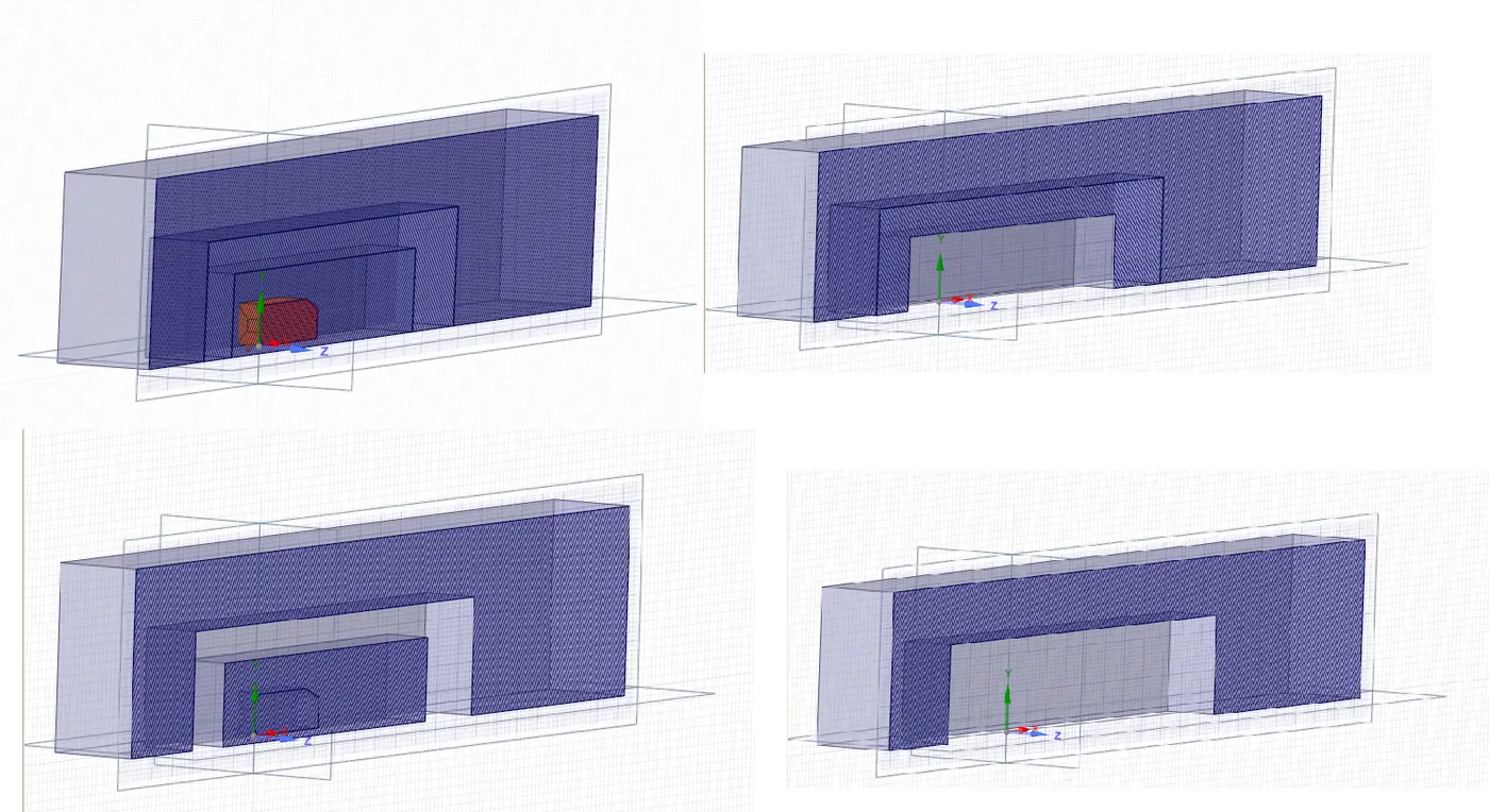
- For accurate body simulation, we must create an enclosure for the geometry to set like wind tunnel testing.
- Prepare an enclosure by disabling the symmetric option because it would cause disturbance during the creation of the enclosure at the base of the body.
- Design a plane for all axes by selecting the origin.
- The model can be solved with more enclosures to get more results with a similar procedure.
- Interference must be ensured for more enclosure, and shared topology must be enabled.
- Disabling the body for physics is essential, or it would interfere with the Meshing part, which is not necessary.
Respective figures:
Mesh:
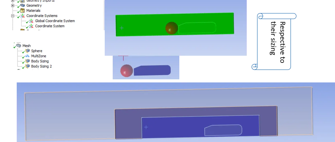
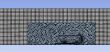
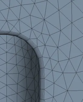
- Generate base mesh for the given model.
- Create further enclosures and do general mesh with Ansys default criteria.
- Base mesh gives ideas for increasing mesh quality, and further refinement makes it easier.
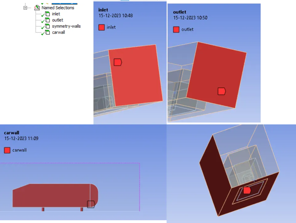
- Naming the sections is the most important.
- Creating a section plane makes the understanding of the section clearer.
Respective Figures:

Setup and Solution:
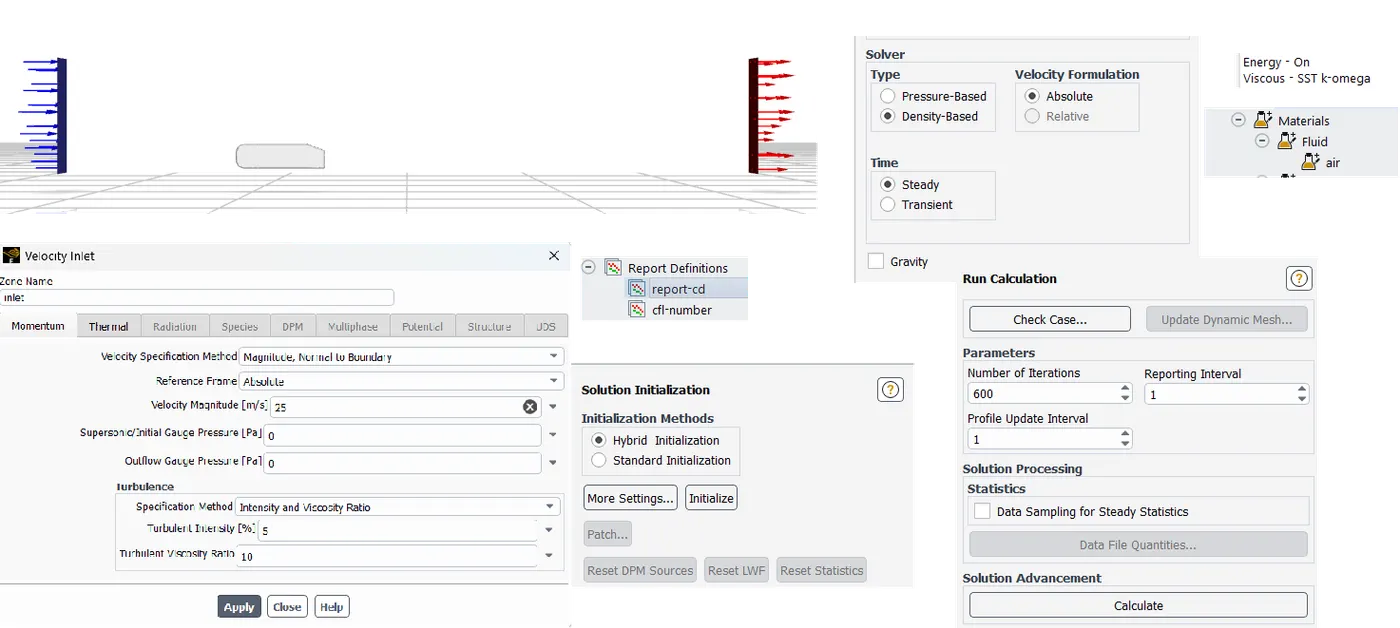
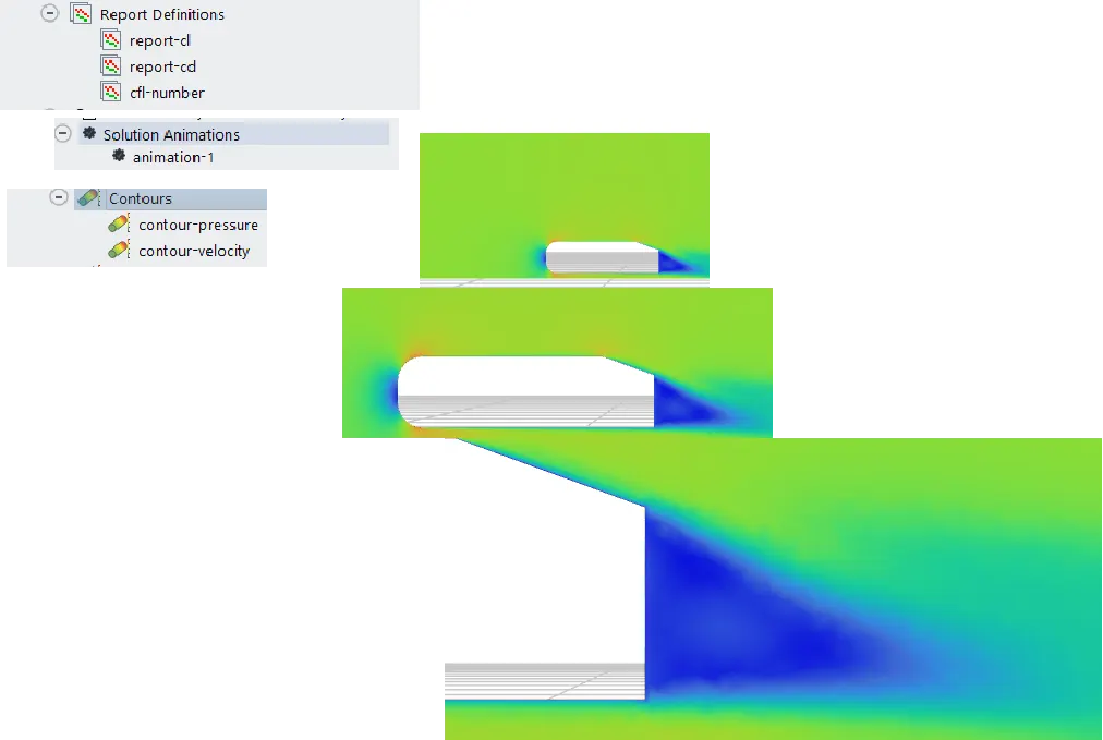
- Creating a plane is more important to visualise the results because we can display results by stating the plane.
- Density-based steady-solving approach.
- k- epsilon
- Energy on and Hybrid initialisation.
- Report definition for both force reports, namely lift and drag.
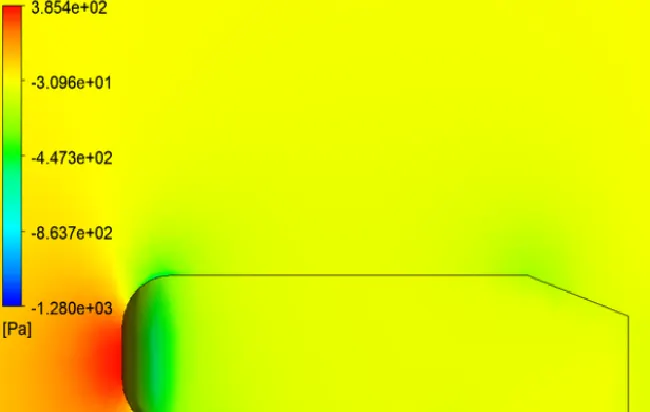
- Velocity and pressure contours and velocity animations.
Respective figures:
Results:
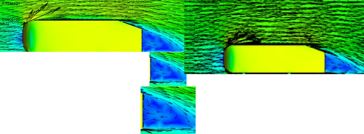
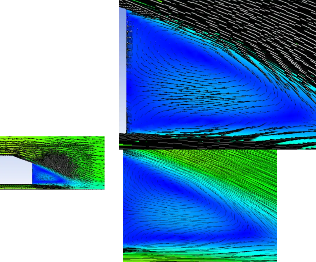
1. The vector plot clearly shows the wake region.
Respective figures:
After fining,
Like the introduction of a sphere near the end to capture the change,
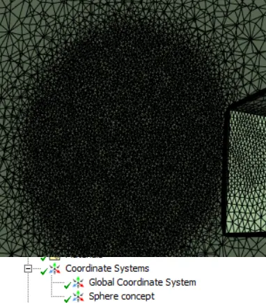
the mesh is captured,
2. Perform the grid independence test and provide the values of drag and lift with each case.
Here, we are comparing the two respective cases.
CASE 1:
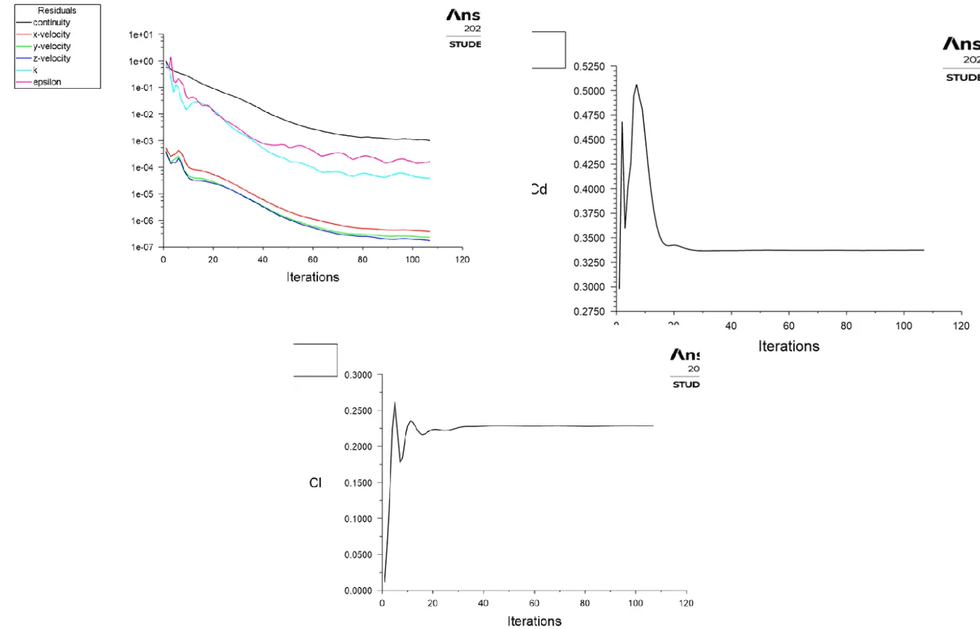
CASE 2:
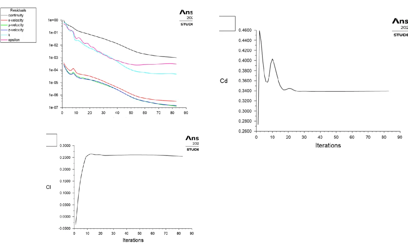
From the figures,

The change is very small even if the mesh size differs, which ensures results are qualified from the grid test.
----XXX----XXX----XXX----
Observation:
- From the initial Ansys base simulation, the CFD results were inaccurate in the mesh region by causing overlapping.
- The grid independence test shows the best results close to the experimental data.
- Refining the mesh size with the y+ factor significantly reduces the error.
- The y+ is chosen between a stable range to predict velocity and pressure contour plots correctly.
- The flow separation and appearance of vortices get more prominent as y+ is increased.
- Proper wake formation is captured correctly when the mesh is appropriate. On refining the mesh, the flow is captured to make sense.
- There are regions behind the body where wakes are formed, circling regions of low velocity, which induce considerable velocity drag on the body.
- A Grid Dependence Test was conducted for validation.
Textbooks and References:
- IC Engines Fundamentals by John B. Heywood.
- Dieler Anselm., The passenger car body, SAE International, 2000
- James E Duffy, Body Repair Technology for 4-Wheelers, Cengage Learning, 2009.
- Pawlowski, J., Vehicle Body Engineering, Business Books Ltd., 1998.
- Braithwaite, J.B., Vehicle Body building and drawing, Heinemann Educational Books Ltd., London, 1997.
- Giles, G.J., Body construction and design, Illiffe Books Butterworth & Co., 1991.
- John Fenton, Vehicle Body layout and analysis, Mechanical Engg. Publication Ltd., London, 1992.