Week 2 - Flow over a Cylinder.
The Kármán vortex street is a phenomenon in fluid dynamics that occurs when a fluid (liquid or gas) flows around a cylindrical object. Named after the Hungarian-American engineer and physicist Theodore von Kármán, this phenomenon is characterised by alternating vortices on either side of the object.
Flow Around a Cylinder:
When a fluid flows around a cylindrical object, such as a cylinder or a sphere, it encounters resistance and is forced to separate and rejoin on the other side.
Formation of Boundary Layer:
- A boundary layer is formed as the fluid flows over the cylinder's surface. The boundary layer is the thin fluid layer adjacent to the surface with significant viscosity effects.
- This layer can be laminar (smooth and orderly) or turbulent (chaotic and irregular).
Vortex Shedding:
- Vortices are shed from the object's edges as the fluid flows past the cylinder.
- These vortices are created due to the interaction between the boundary layer and the free stream of the fluid.
- The shedding of vortices alternates from one side of the cylinder to the other.
Alternating Vortices:
- The vortices form a pattern known as a Kármán vortex street. These vortices trail downstream of the cylinder in a distinctive, alternating pattern.
- The vortices are shed at a characteristic frequency, which depends on the object's size and shape and the fluid flow speed.
Frequency of Vortex Shedding:
- The frequency at which the vortices are shed is known as the Strouhal number.
- It is a dimensionless parameter that relates the shedding frequency to the flow velocity and the diameter of the cylinder.
The Kármán vortex street is a common and visually striking phenomenon observed in various natural and engineering contexts, such as the wake behind a bridge pylon, the flow around buildings, and the wake behind a swimmer or a fish. It has implications in aerodynamics, civil engineering, and the study of fluid dynamics. Engineers and scientists often use the insights from studying Kármán vortex streets to optimise designs and minimise the effects of vortex-induced vibrations.
PART - I and II
OBJECTIVE:
1. Simulate the flow with the steady and unsteady case and calculate the Strouhal Number for Re= 100.
2. Calculate the drag and lift coefficient over a cylinder by setting the Reynolds number to 10,100,1000,10000 & 100000. (Run with steady solver)
Answer:
Simulation part
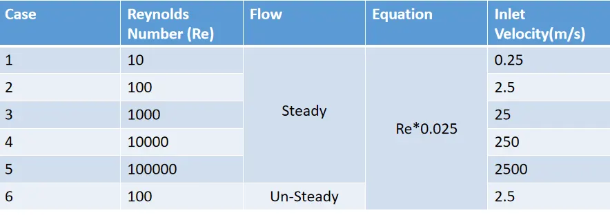
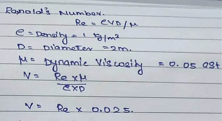
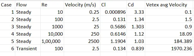
The conditions are similar except for the solving process, so let's delve into the simulation. The above Table shows the different velocity values for respective Re (Reynolds Number).
Geometry:
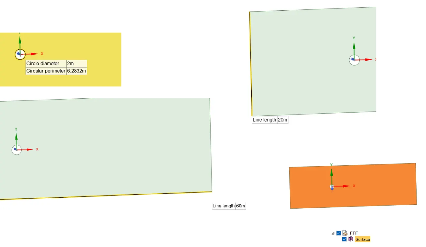
- Open Space claim.
- Change to the required Units.
- Once the Geometry is completed in the sketch plane, use the pull option to make it two-dimensional.
- The origin must be at the centre because it helps in future points in describing the Monitor points during analysis.
- Update to Mesh.
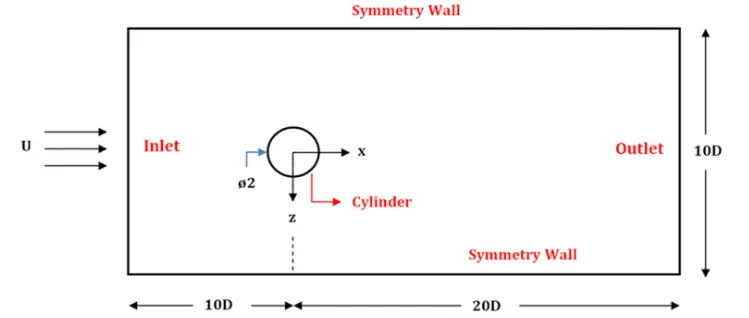
Respective figures:
MESH:
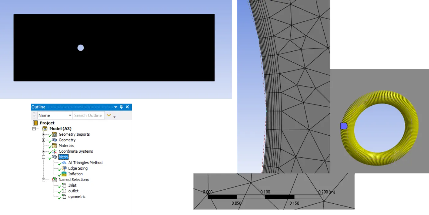
- Change the mesh model to a triangular one by inserting the methods option.
- Sizing of the cylinder part must be sized properly. Otherwise, it would cause damage to the flow area.
- Sizing must be in the clearance for 10 degrees so we can choose for circle as 36.
- Further reduction can be done, but it would cost in the sell size.
- The area near the circle should be processed with inflation layers for perfect mesh.
- The first layer thickness and growth size must be valuable.
- Name the sections
- Update the mesh size.
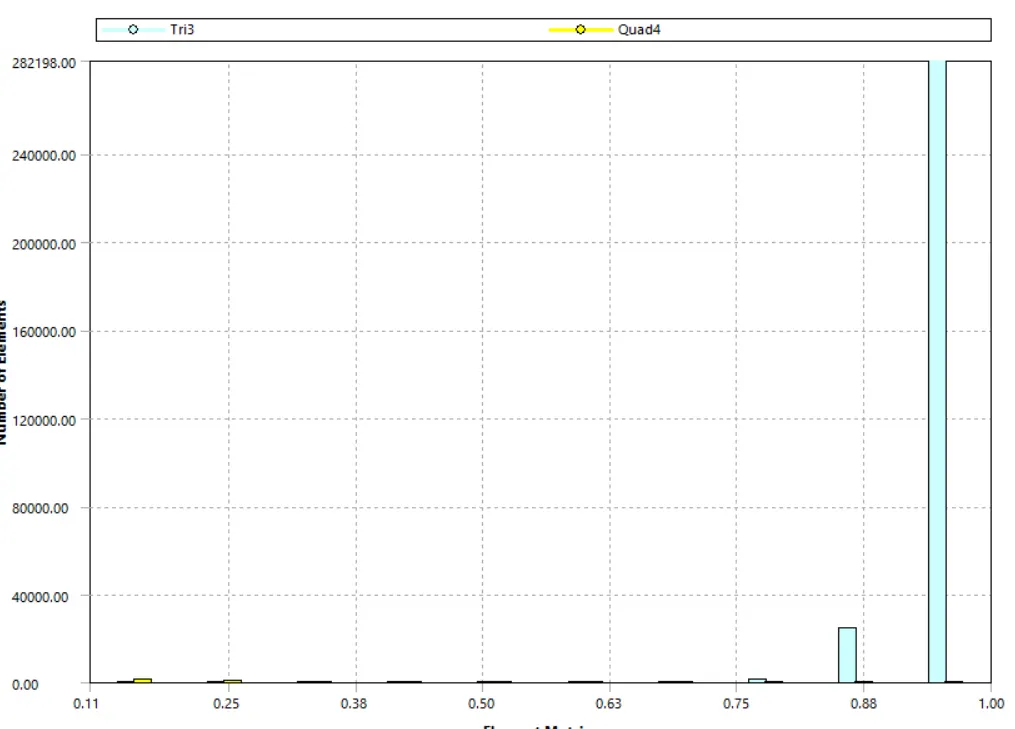
- Element size always affects the results and takes appropriate time if the mesh count drops too low.
- So, selection must verified in element quality.
Respective figures:
Setup:
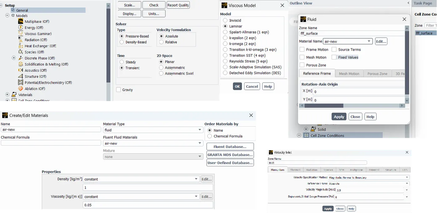
- ANSYS automatically takes air as the working fluid.
- So, Choosing the right fluid is necessary.
- Here, density in one and viscosity is 0.05, as mentioned above in the table.
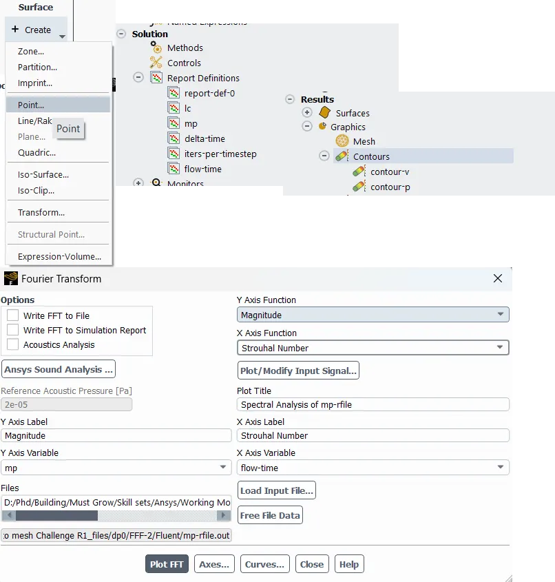
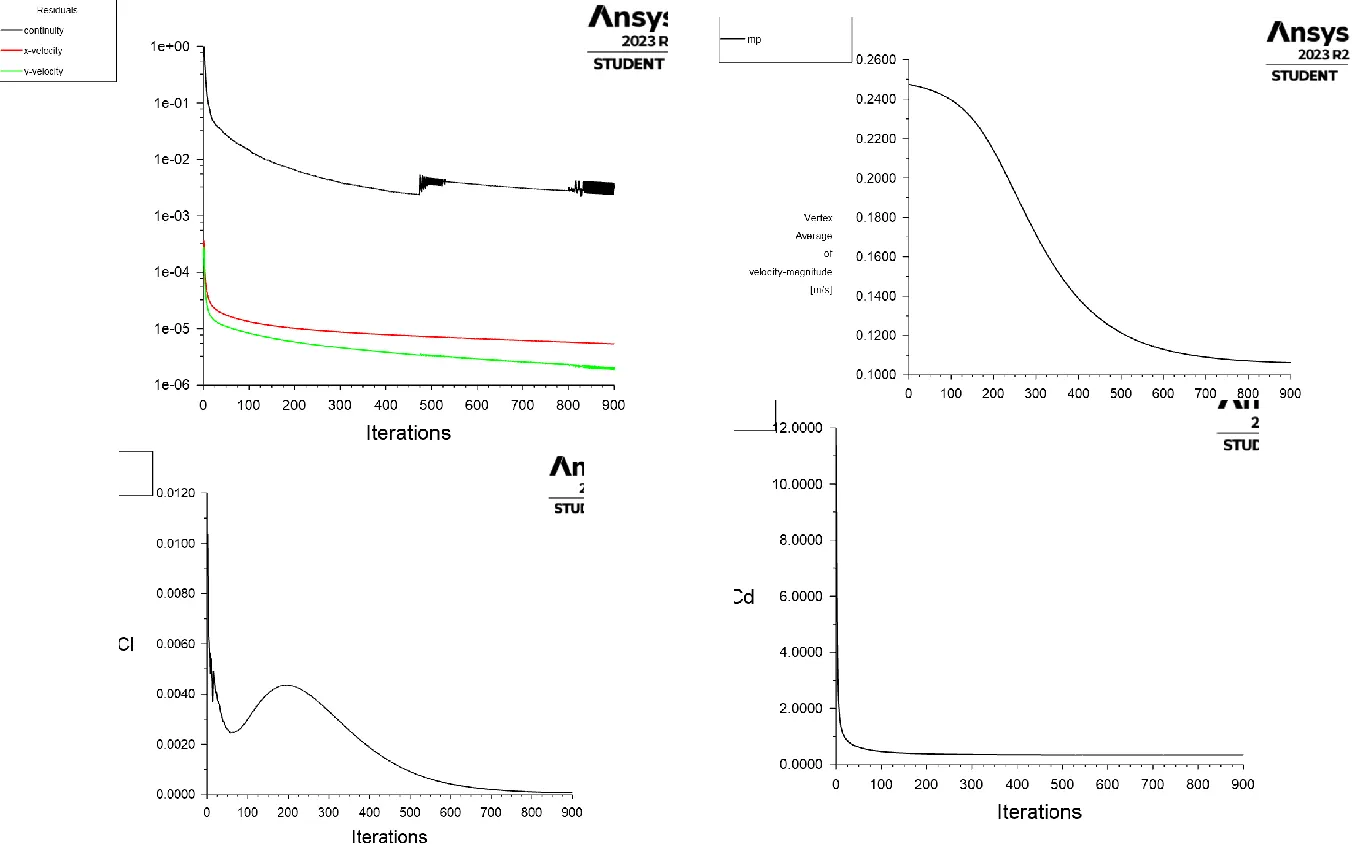
- A new monitor point should be created for the validation of the results.
- Both steady and transient are solved for Re 100; the remaining are only done in the steady flow process.
- Solution is SIMPLE
- Boundary conditions of inlets are varied for different cases.
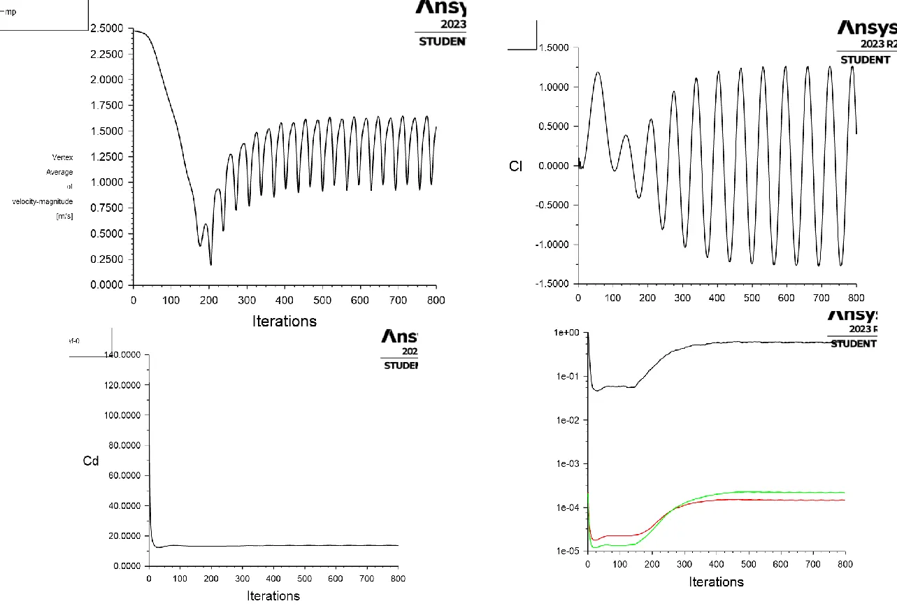
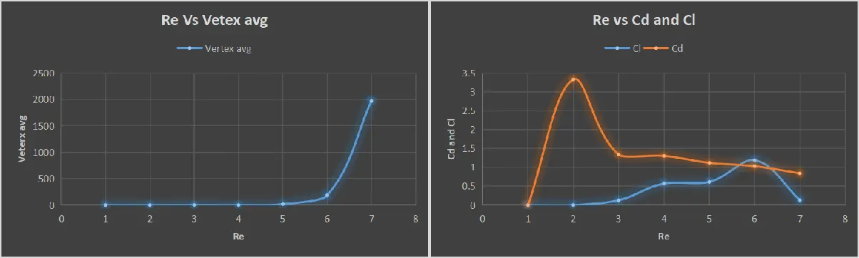
- Reports from the part of the definition are created for the results (vertex avg).
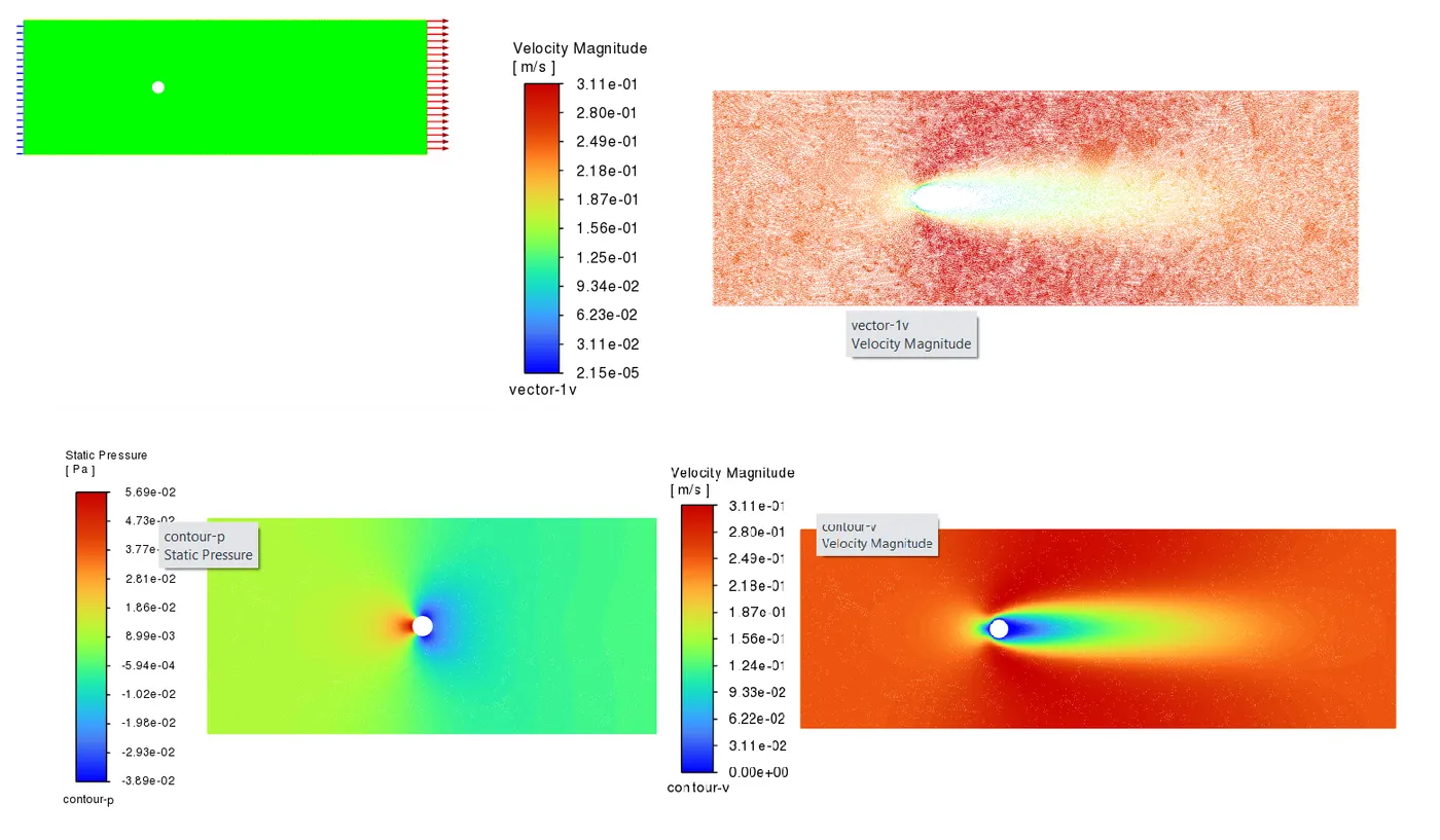
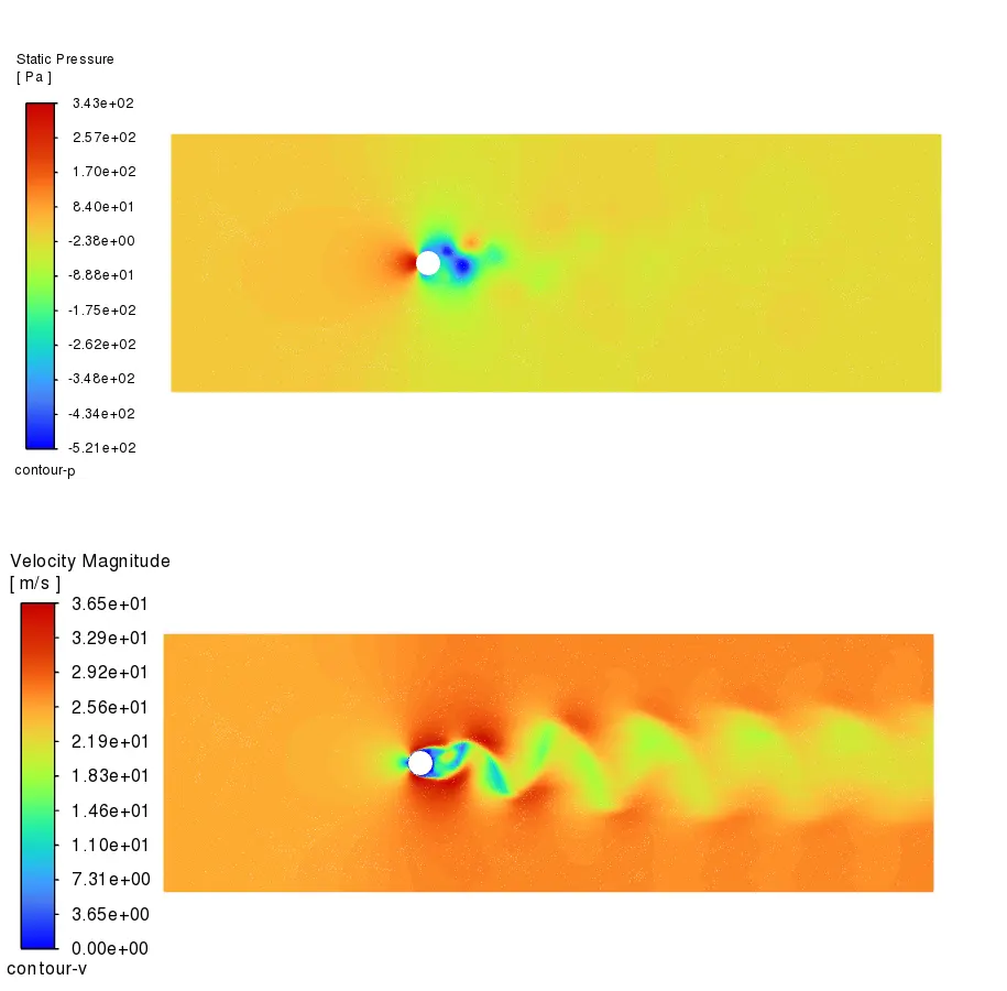
- Pressure and Velocity contours are created.
- The solution animation for contours is updated.
- Initialisation and Calculation parts are successfully done.
Strouhal Number:
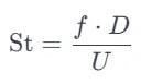
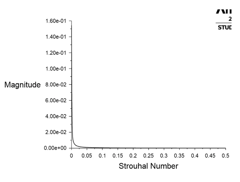
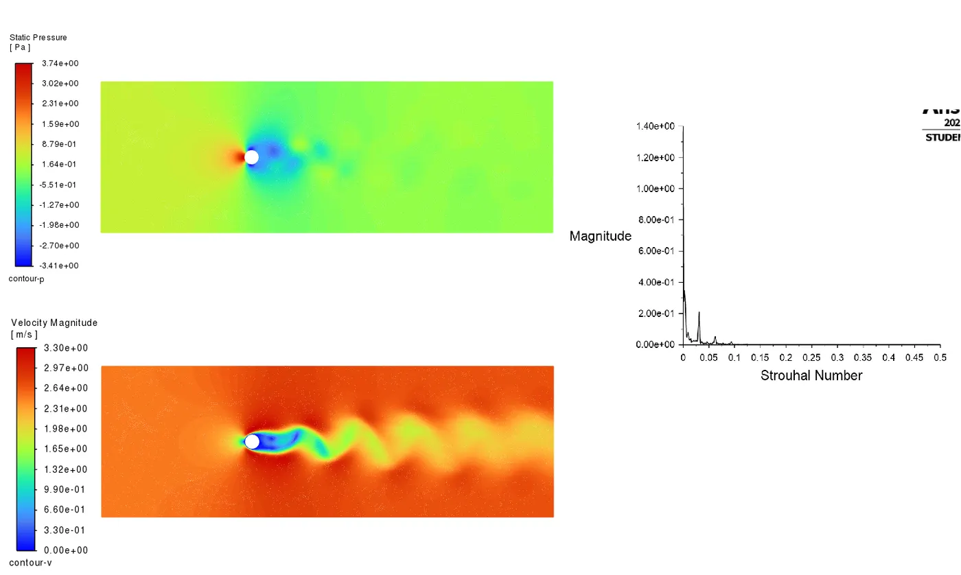
The Strouhal number (St) is a dimensionless quantity used in fluid mechanics to characterise fluid flow around a bluff body, such as a cylinder. It is named after the Czech physicist and engineer Vincenc Strouhal, who first investigated the relationship between the frequency of vortex shedding and the flow velocity around a cylindrical object.
The Strouhal number is a dimensionless parameter that helps describe the unsteady flow phenomena, specifically the shedding of vortices behind a bluff body. It is commonly used in aerodynamics, fluid dynamics, and civil engineering. The Strouhal number helps predict when vortex shedding will occur and how frequently it will happen.
In the context of the Kármán vortex street phenomenon, the Strouhal number provides information about the regularity and frequency of the vortices shed by a cylindrical object in a fluid flow. Different objects and flow conditions will result in different Strouhal numbers, and understanding this parameter helps engineers and scientists design structures and systems that minimise the impact of vortex-shedding-induced vibrations and other undesirable effects.
Case 1 :
Case 2 :
Case 3 :
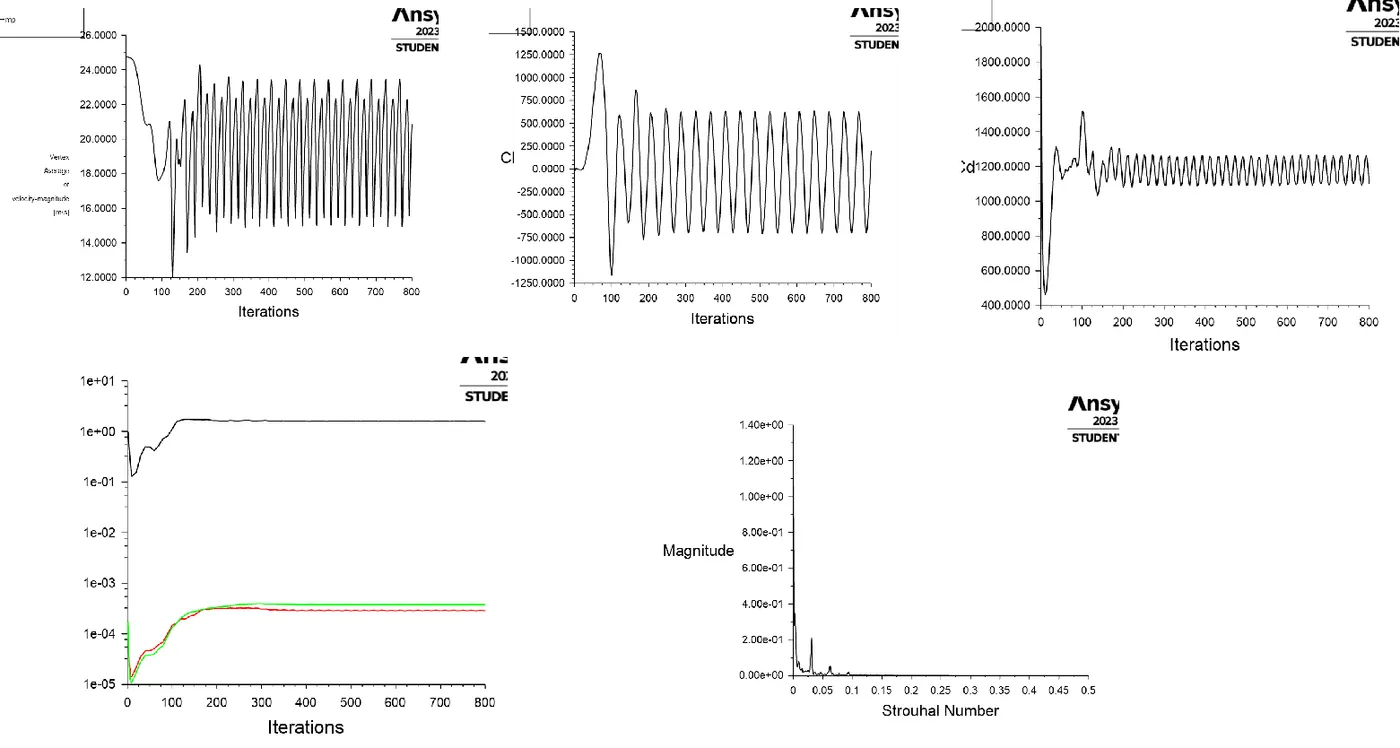
Case 4 :
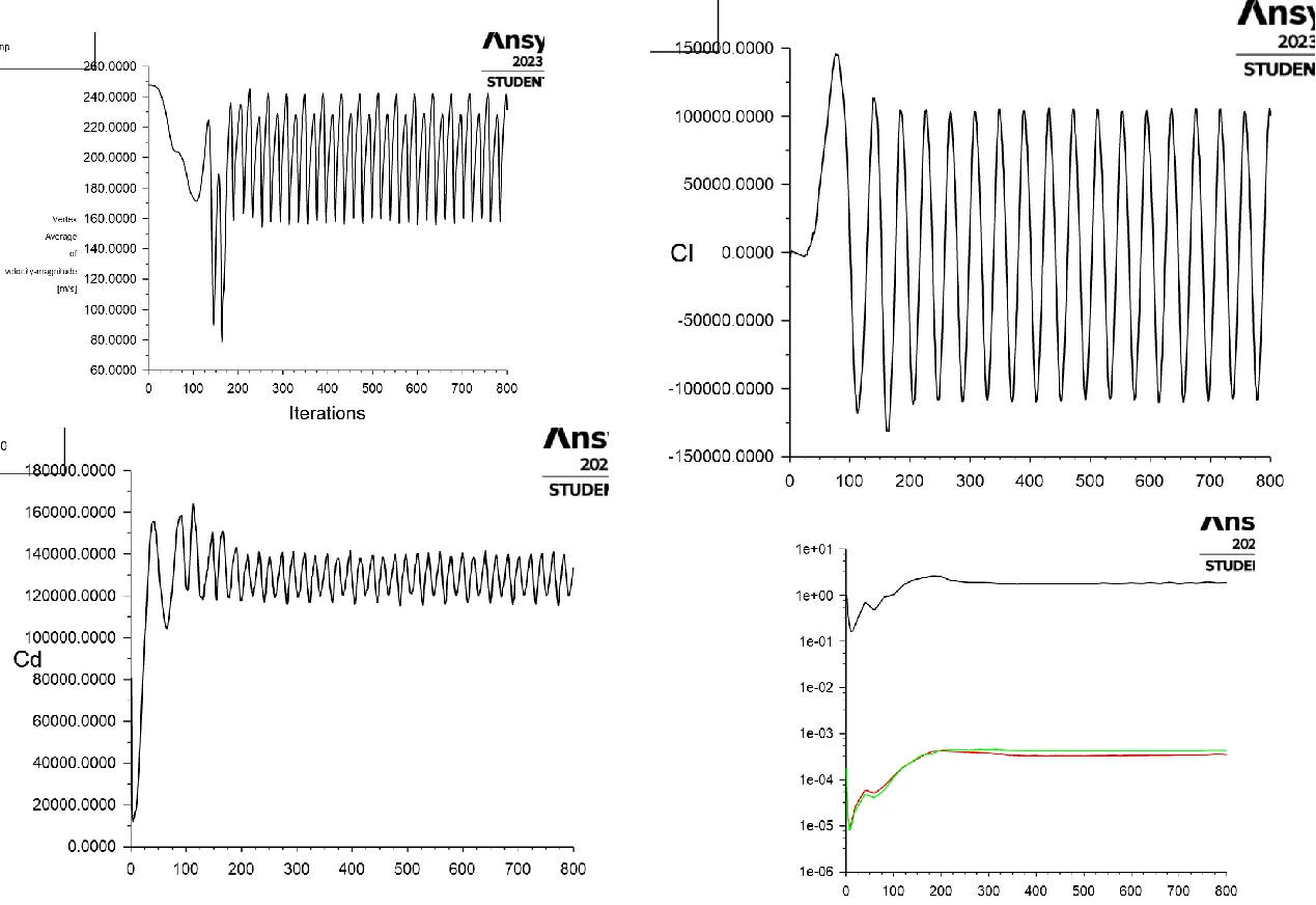
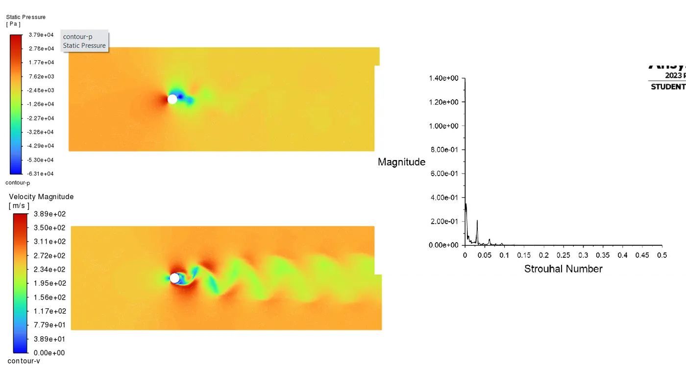
Case 5 :
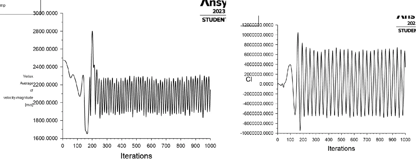
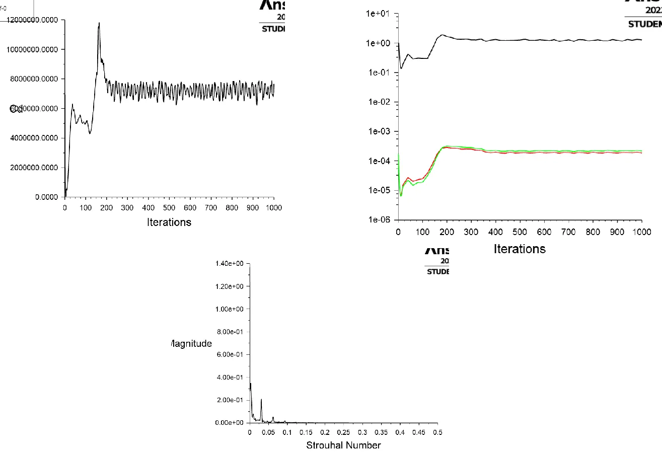
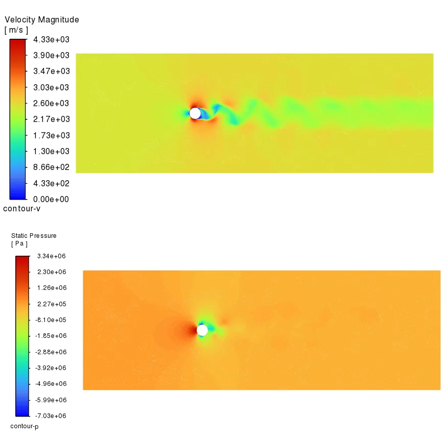
Case 6 :
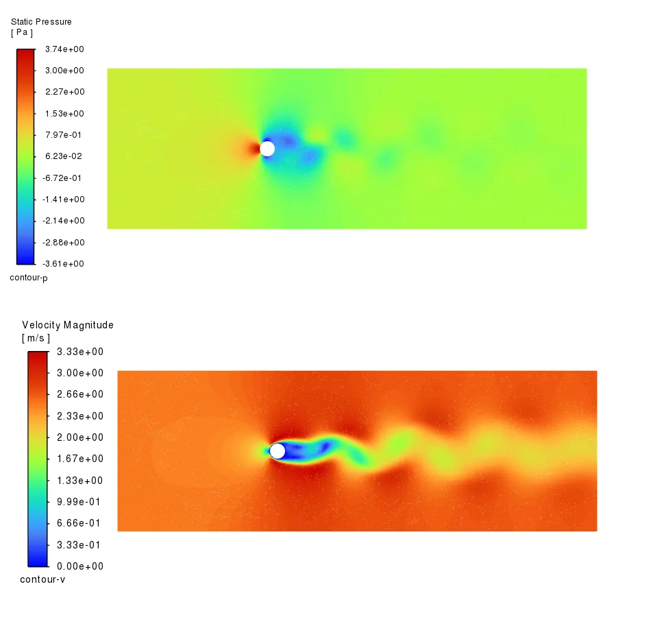
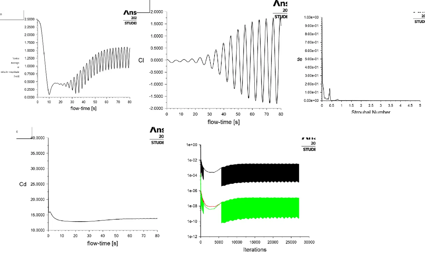
Graph Plots:
ANIMATIONS:
Animations are compiled into a single Link below
https://drive.google.com/drive/folders/1JjPBFiSZXZv0YvEyPg2CYcoIBr0hl1D-?usp=sharing
References:
1.https://en.wikipedia.org/wiki/Theodore_von_Kármán
2.https://en.wikipedia.org/wiki/Kármán_vortex_street
3.https://en.wikipedia.org/wiki/File:Vortex-street-animation.gif
4. D.D. Barkley, R.D. Henderson, Three-dimensional Flow stability analysis of the wake a circular cylinder, J. Fluid Mech. (1996).
5. https://www.sciencedirect.com/science/article/pii/S0307904X08000243