Week 3 - External flow simulation over an Ahmed body.
Aim:Validation of external air flow over Ahmed body.
Objective:
- To study the ahmed body as basic of simulation for external over vehicle.
- To study the evalution of Y+ value and its importance for simulatoin.
- To pre-process the geometry and mesh for ahmed body simulation.
- To refine the mesh and study the effect of coefficient of drag on the ahmed body.
- To perfrome the mesh and study the effect of coefficient of drag on the ahmed body.
- To perfrom the mesh independent test for Ahmed body simuation.
Ahmed Body:
The Ahmed body represent a simplified, ground vehicle geometry of bluff body type. Its shape is simple enough to allow for accurate flow simuation but retains same important practical features relevent to automobile bodies. This modal describes how to calculate the turbulent flow field around a simple car-like geometry.
The airflow around body captures the essential flow features around on automobile and was first defined and characterized in the experimental work of ahmed althrough it has a very simple shape, the ahmed body allows us to capture caracterstic features that are relevent to bodies in automobile industry.
Ansys is general-purpose FEA and CFd simuation software. It gives a numerical prediction of the behaviour of system. These numerical predications need to be validated by experimental data.
This modal is also used to describe the turbulent flow field around a car -like geometry. people working in vehi
cle aerodynamics use Ahmed body to validate their numerical modal because the experimental data from wind tunnel testing is availble for ahmed body. Once the numerical modal is validated, it is used to design new models of the car.
The Ahmed body was described originally by S.R.Ahmed in 1984. Three main features were seen in the wake.
- The recirculation region that is formed due to the seperation at the base of the model.
- The B recirculation region that is fromed due to the seperation at the base of the model.
- The C-pillar vartices that from as the varticity in the side boundary layer roll up over the slant edge.
The wake was shown to be highly dependent on slant angle. for slant angles less than 12 degree the flw remain attached over the slant. the flow is essentially two-dimensional and has low drag. Between 12 and 30 deg the flow becomes much more three- dimensional as the c-pillar varties from. These reach maximum strength at 30 deg. The drag increases significantly as the low pressure cores act the rear surfae. Past 30 deg the flow seperates fully off the slant. This results in a sudden decrease in drag and weaker c-pillar vartices.
Importance of ahmed body
The drag force is an important factor considering fuel consumption. As the drag force increases the fuel consumption also increases which in turn becomes expansive for the car owner. As the burningof fossil fuel because an issue.The manufactures arepressing for fuel-efficient cars. One of the main factor considering the car is fuel-efficient or not is the car's geometry.
Complex shaped cars are very challenging to model and its difficult to quantity the aerodynamic drag computationally. The Ahmed body is a benchmarh model widley used in automotive industry for validating simulation tools.
Negitive pressure in the wake region
When the air moving over the vehicle is seperated at the rear end, it leaves a large low-pressure turbulent region behind the vechile which is known as the wake. this contributes to formation of pressure drag which affect the vehicle perfromance.
When the vecile is moving at a certain velocity the fluid imports viscous force to the vehicle as long as it is in the viscous sublayer of the boundary. When the fluid reaches the rear end of the vehicle it gets detached from the surface of body causing negitive pressure in the wake region. the movement of the fluid around the vehicle dependes on the geometry of the car and the reynolds number.
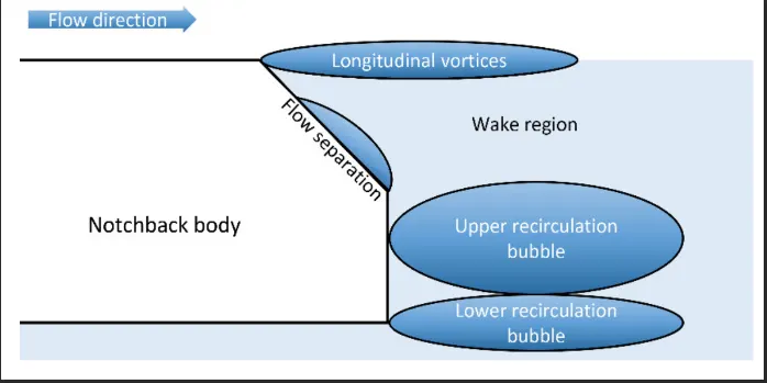
Significsnce of point separation
The point of separation will occur when there is a discontinuity in the surface or a region of the negitive pressure gradient (a sharp end or rear portion of the car).
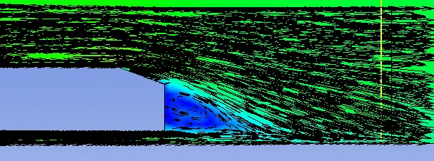
When the flow is attached to the body of the vehicle the viscous force will increase which will increase the pressure and a decrease in velocity before the rear end of the vehicle. As soon as the air encounters the sharp turn cousing the velocity to decrease resulting in the negative pressure region which in the wake region. The recirculation region happens beyond the point of separation.
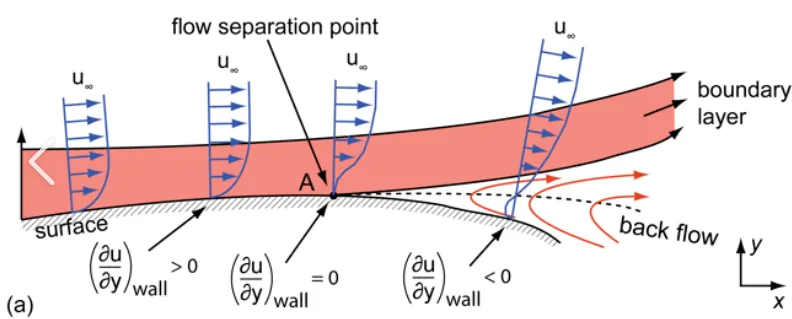
If the rate of change of pressure is large the mixing process will not occur and the boundary layer flow stops.
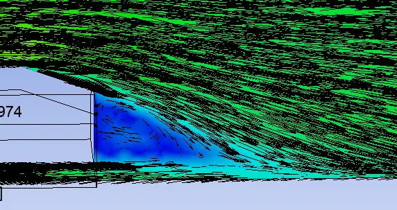
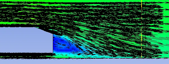
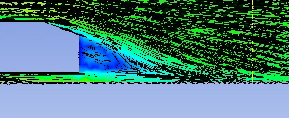
The above figure shows that at the point of turning the flow gets separated from the boundary layer and there is a region of recirculation after which the flow attaches itself to the boudary layer.
In order to reduce the seperation of fluid from the boundry layer, it isadvisble to have a smooth edge to reduce the effect of drag on vehicle.
Geometry:
First, we need to set up the geometry of ahmed body for simulation.\
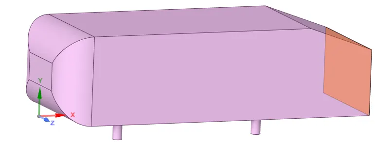
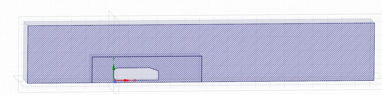
- Create the enclosures around the ahmed body for base line mesh.
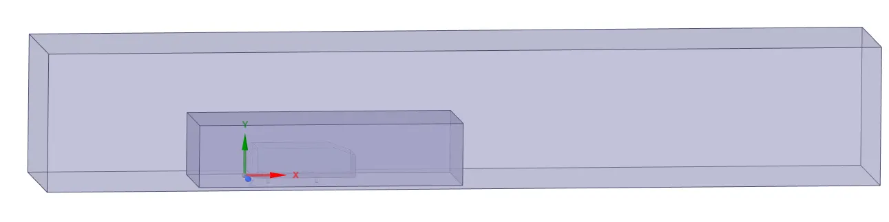
Outer enclosure
- The outer enclosure is at a distance of 2m from the Front side of the Ahmed body in the X-axis.
- The outer enclosure is at a distance of 5m from the Rear side of the Ahmed body in the X-axis.
- From the top, it is at a distance of 1m in the Y-axis.
- At the bottom, it is merged means it is at zero distance.
- From the left and right side of the Ahmed body, it is 0.5m along Z-axis.
Inner enclosure
- The inner enclosure is at a distance of 0.5m from the front side of ahmed body in X-axis.
- The inner enclosure is at a distance of 1m from the rear side of the ahmed body in the x-axis.
- From the top, it is at distance of 0.5m in the y-axis.
- At the bottom, it is merged means it is at zero distance.
- From the left and right side of the Ahmed body, it is 0.26 along Z-axis.
Interfrence region:
- Initially, there was a huge interference between the outer and inner encloure so mesh gets overlapped which gets not acceptable so to aviod this we made share topology and get deleted the interference region by using the interference command after this we get a good interaction between the inner and outer enclosers so that we can get the mesh properly.
Mesh
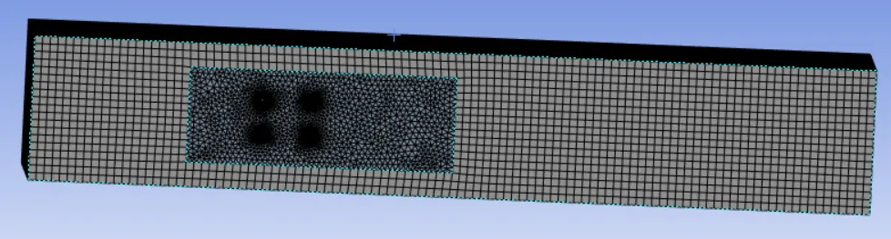
- Generating the mesh on the enclosures around Ahmed Body, the outer enclosure has Hexahedral grids to capture the flow structure and the inner enclosure has the Tetrahedral grids and inflation layers has created along the walls of the Ahmed body to capture the point of separation at the wake region clearly.
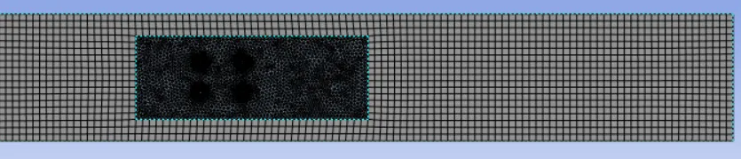
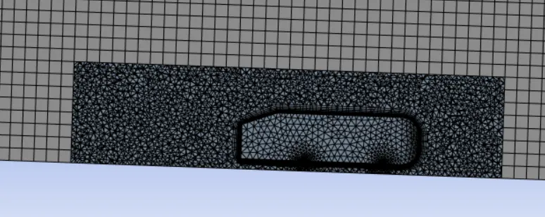
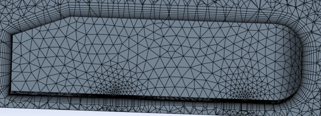
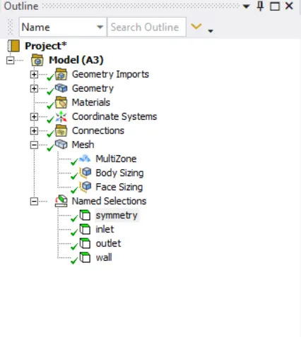
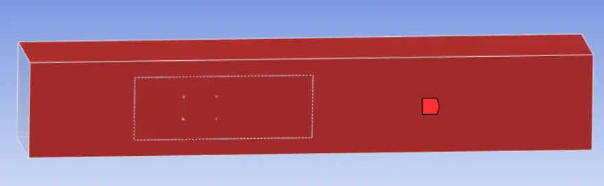
- By using the named selection command we are assigning the boundaries thet are front side of the ahmed body inlet, Rear side as outlet and also the top,botton,left and right sides as symmetry condition and Ahmed body as car-wall.
Set-up:
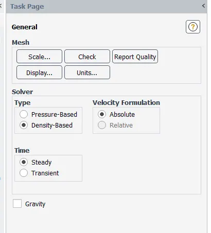
- For the solver setup as discussed earlier, we have used pressure based solver rather than density based solver by calculating Reynolds number for flow. The fluid which is used throughout the simulation is air and the proprties are given below:
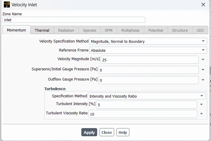
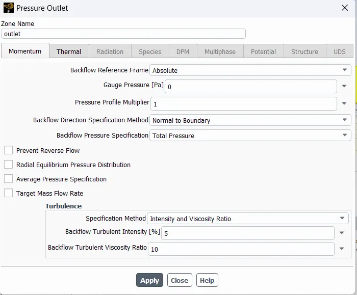
- In the next we open the boundary condition and inlet to open and giving the velocity 25 m/s.Outlet type is pressure -outlet and the gauge pressure is 0.The wall to considering the no slip to evaluate deag and lift coefficient.
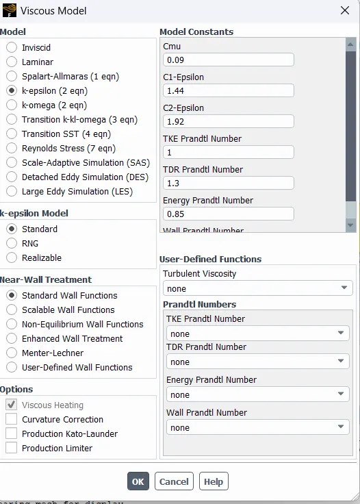
- The turbulence model which is used for the simulation is k-epsilon with standard model having standared wall function as near wall treatment.This modal provides great result accuracy near the wall of Ahmed body.The calculation of Y + value is also depend on the which wall tretment is used.
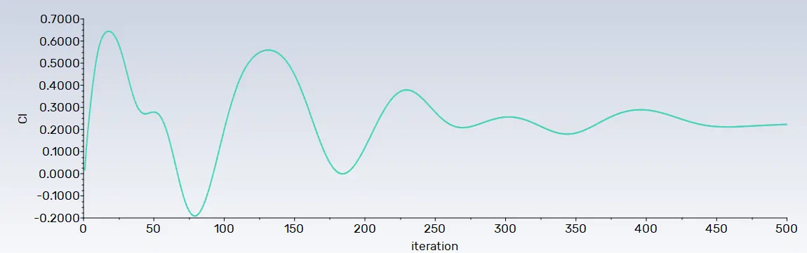
- For the calculation of lift and drag coefficient reference value are main attribute need to be provided in the simualtion. Depending upon the area and length specification also from what boundary condition this value are calculated is required. As FLUENt does not have clue fom which area this value has to be calculated.
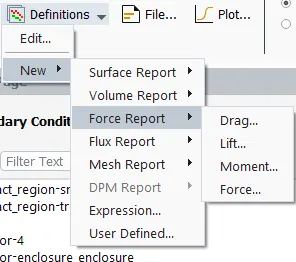
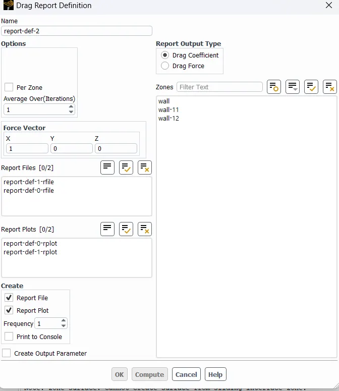
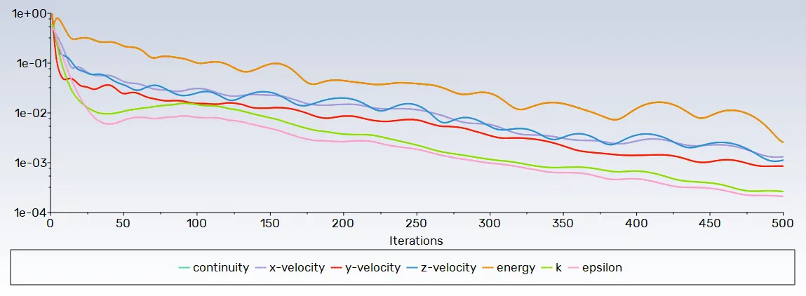
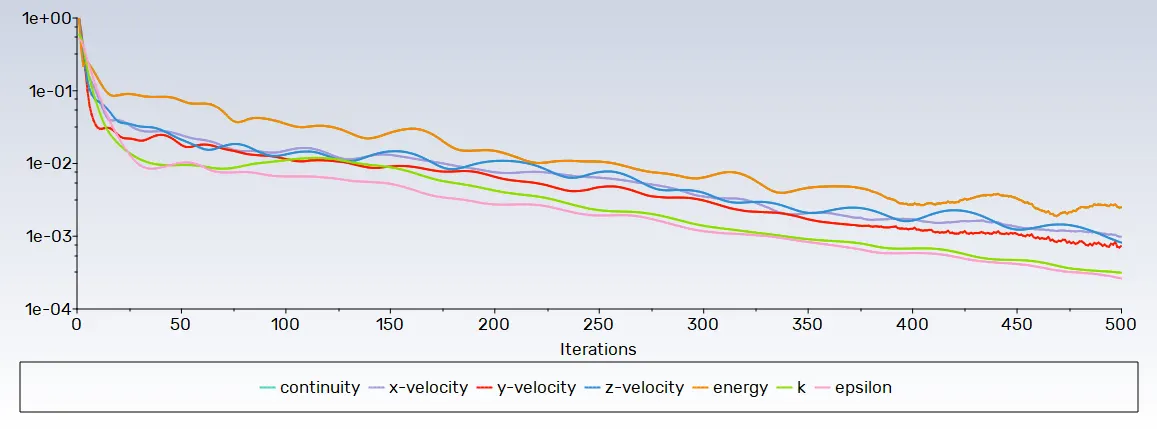
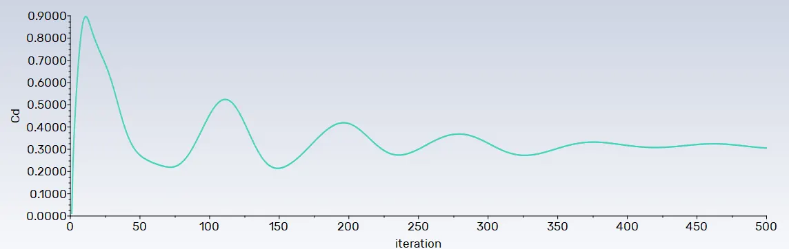
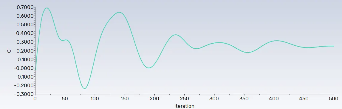
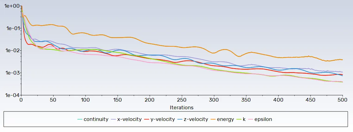
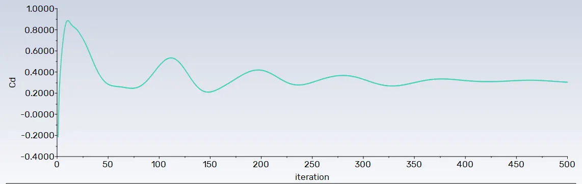
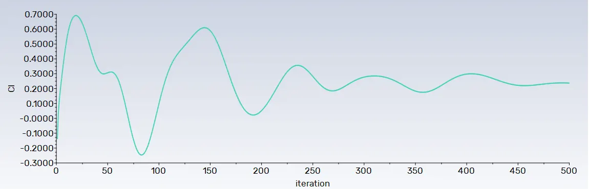
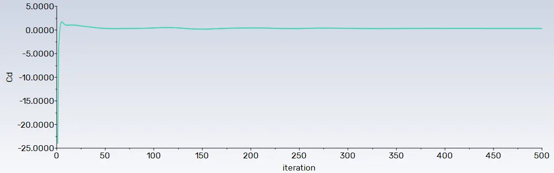
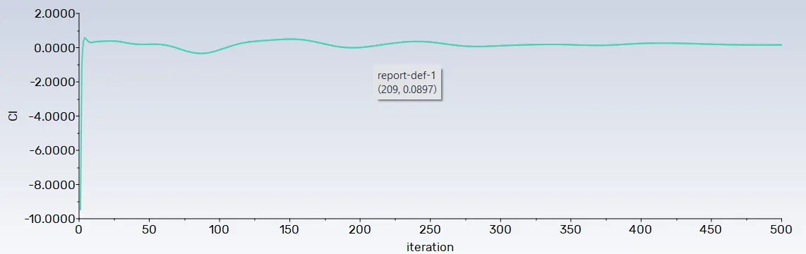
- After providing every value for simuation the last setup is to choose the pressure-velocity coupling schme for problem.Before making intialization to the problem the reports need to be generated which are drag and lift coefficient. This can be accessed from solution report option is FLUENt. In solution report option forces has to be select which further provide option to select drag and lift coefficient or forces. It is necessary to select the wall of which this coefficient has to be calculated.After this it is impotant to see the solution animation as it progresses throughout the simulation process. For solution animation it required the reference frame or plan on which it will show the results.This can be done by using location option in which user can crate plan, surface or point to be used as refernce for solution.After making referance plan,to crate solution animation intilization of problem has to be done before.the number of iteration are around 500 in whish each of the value will be calculated.
Pst-Processing
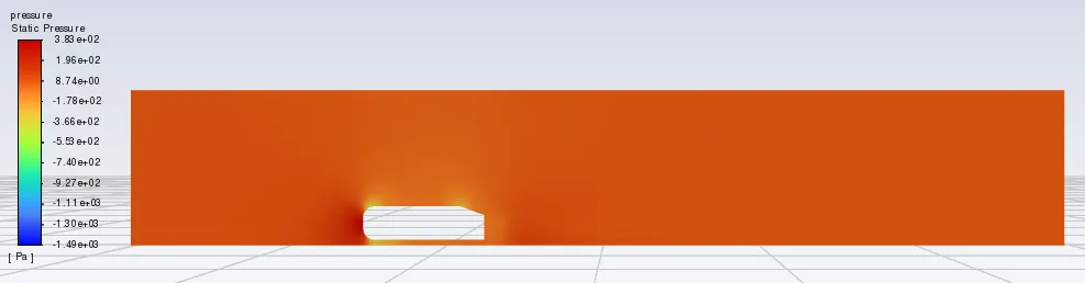
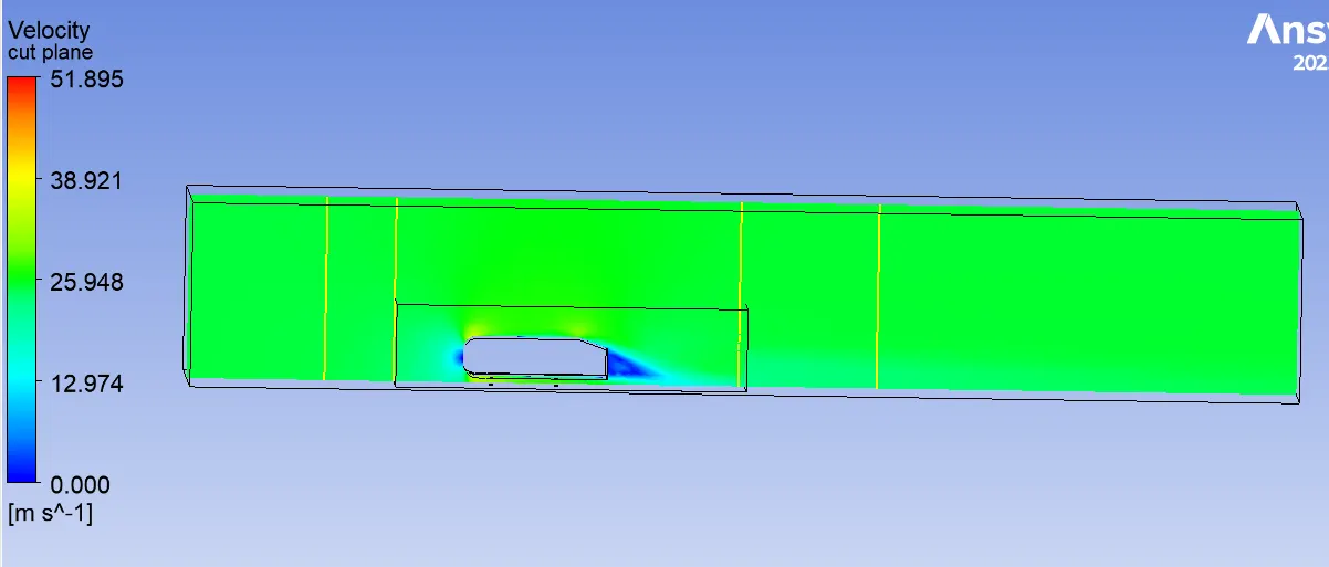
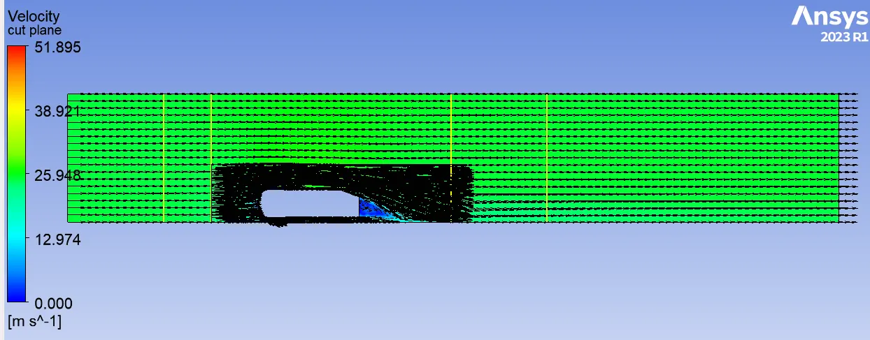
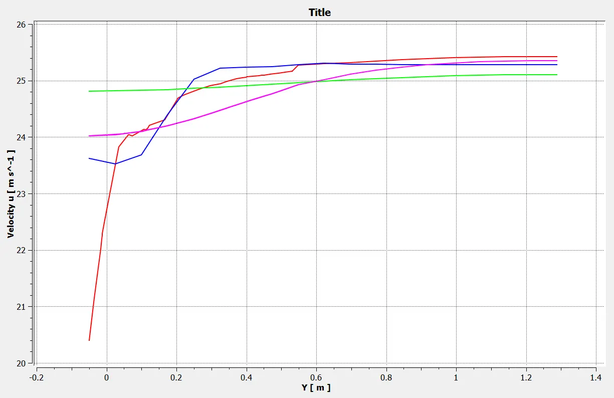
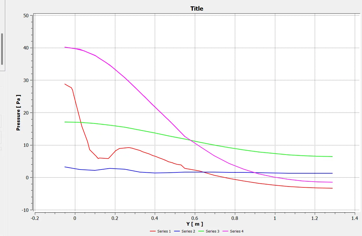
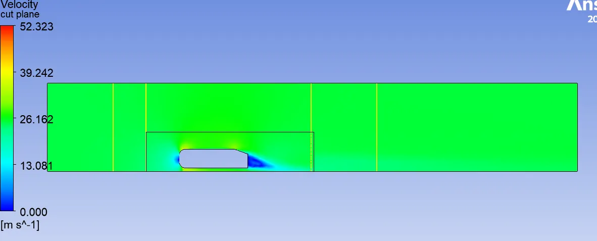
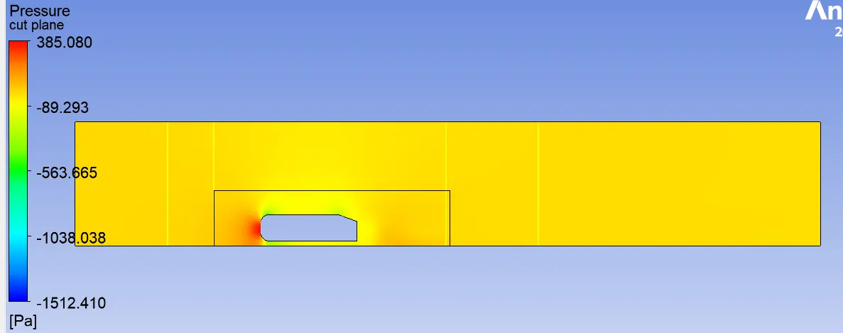
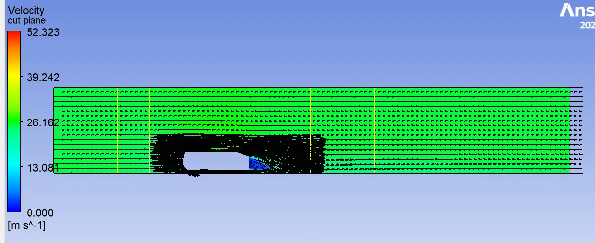
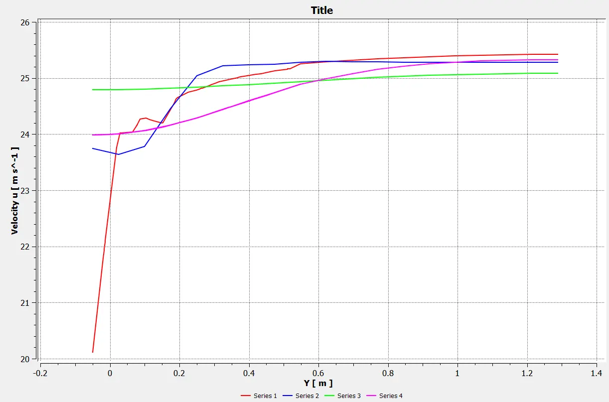
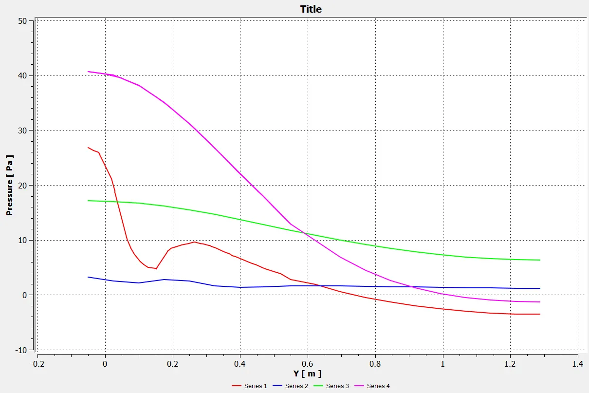
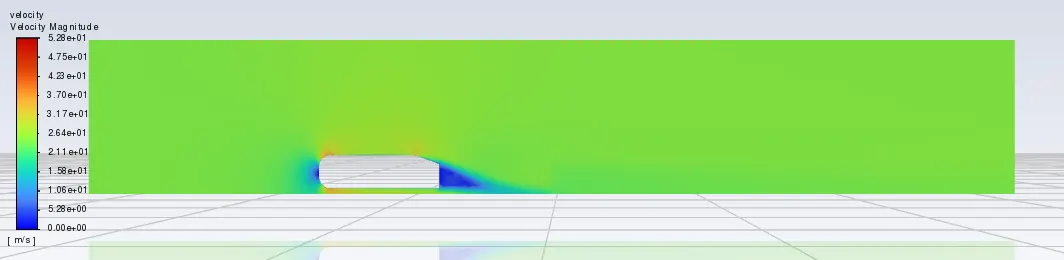
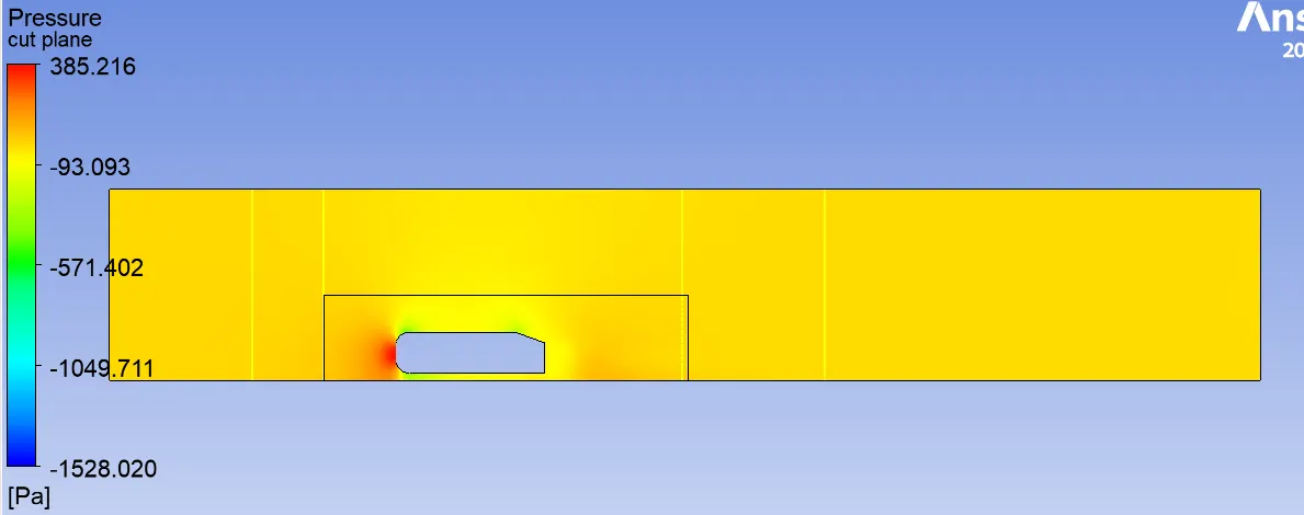
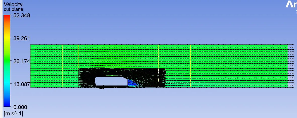
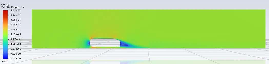
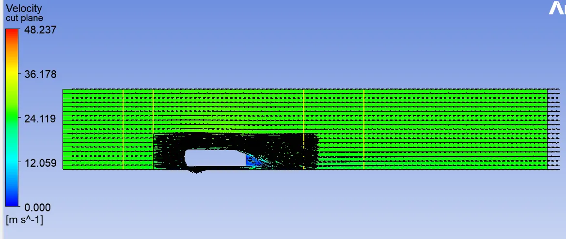
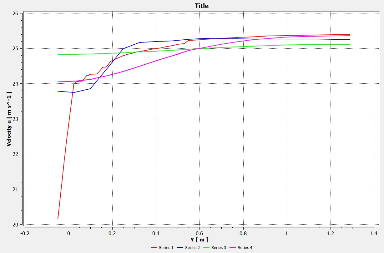
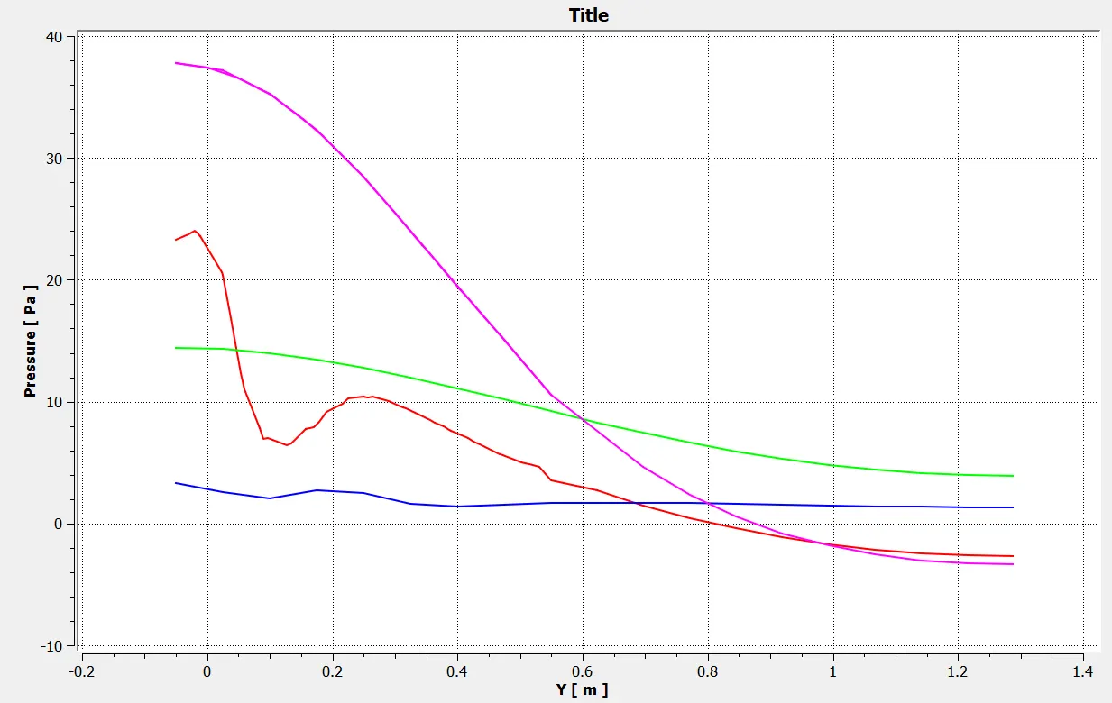
The post processing is required to study the results came from simulation. In post-processing all velocity and pressure contours with vector plot are used to study flow in wake region and point of seperation from Ahmed body model. Another important aspect in the pre-processing is getting the chart of velocity and pressure value in the domain. This id done by using line option and chart option in post-processor. The location has been considered before the body and after the ahmed body. This will provide information on the velocity and pressure co-relation before and after flow region.
Results:
Calculate reynolds number
Re=Density*Velocity*length/dynamic viscocity =1.225*25*1.044/1.7589e-05=1786772.10
Skin friction coefficient
Cf=0.026\Re^(1/7)=0.026/1786772.10^(1/7)=0.00335
Shear stress near the wall
Twall=Cf*density*U*2/2=0.00335*1.225*25^2/2=1.2728N/m^2
Friction velocity
Uf=√(Twall/density)=√(1.2728/1.225)=1.019
Frist layer thickness
Δs=Y-plus*μ/Ufric*Density=100*1.785e-05/1.019*1.225=0.001433m
Case 1:
- Y-Plse=100
- Viscous modal=K-epsillon
- 1 st box domain=75 mm size of hexahedral mesh
- 2 nd box domain=50 mm size of tetrahedral mesh
- Elements=192413
- Nodes=81091
- Inflation layer thickness=1.432

CASE 2:
- Y-Plse=75
- Viscous modal=K-epsillon
- 1 st box domain=75 mm size of hexahedral mesh
- 2 nd box domain=50 mm size of tetrahedral mesh
- Elements=206139
- Nodes=91580
- Inflation layer thickness=1.074
CASE 3:
- Y-Plse=75
- Viscous modal=K-epsillon
- 1 st box domain=75 mm size of hexahedral mesh
- 2 nd box domain=50 mm size of tetrahedral mesh
- Elements=212500
- Nodes=92706
- Inflation layer thickness=0.716

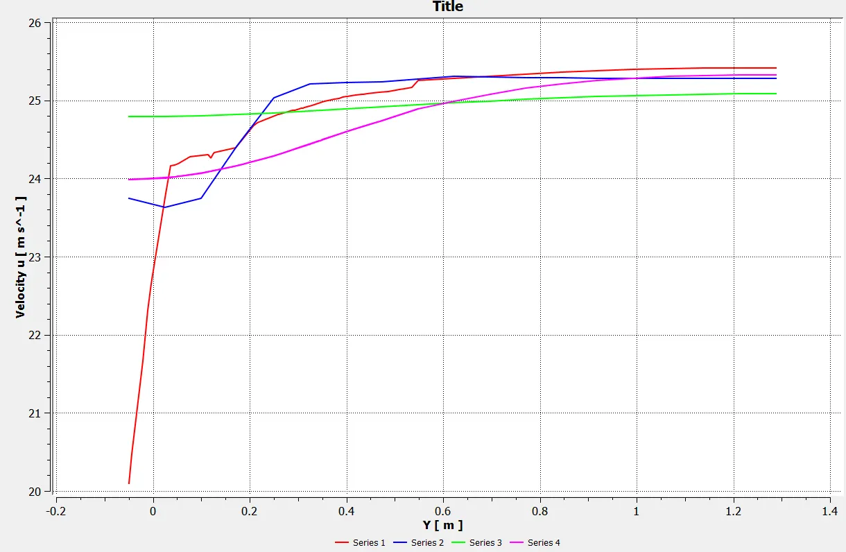
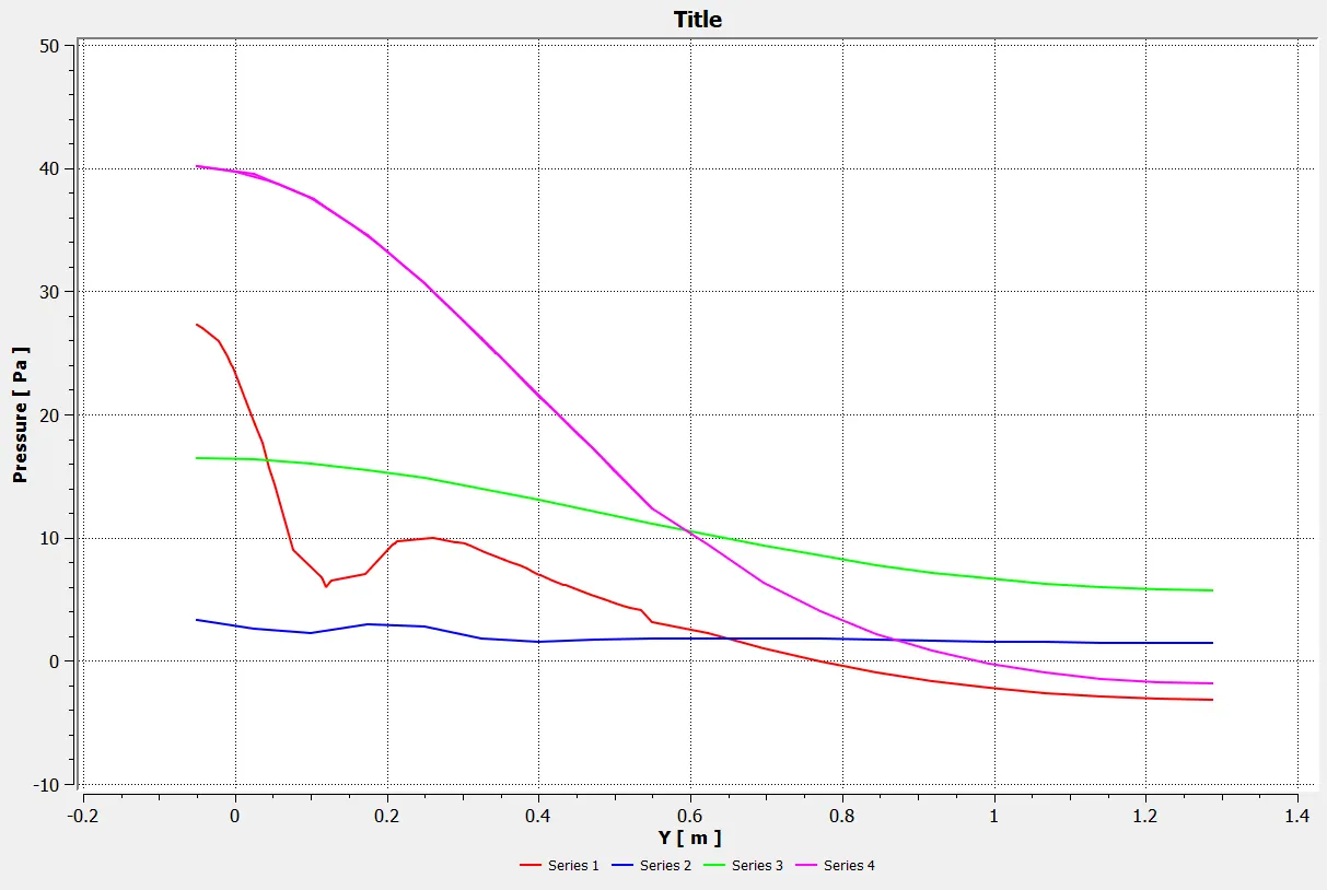
CASE 4:
- Y-Plse=5
- Viscous modal=K-omega
- 1 st box domain=75 mm size of hexahedral mesh
- 2 nd box domain=50 mm size of tetrahedral mesh
- Elements=237093
- Nodes=97004
- Inflation layer thickness=0.0716
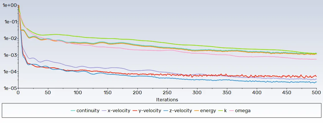
Camparision:
K-epsillon Elements Cd Cl
Case 1 192413 0.302 0.2228
Case2 201639 0.3349 0.2515
Case3 237093 0.3228 0.2372
K-omega
Case 4 237093 0.312904 0.1604
Conclusion:
There is a variation of pressure across the Ahmed body. The pressure in front of thre body is positive because thaat's the location where the flow first comes in contact with body and comes to rest. At the corner, the flow accelerates, thereby decreasing the pressure.
The reason behind negitive pressure in the wake region is due to flow seperation, recriculating flow. It's phenomenon that generally happen as the air moving past the body isn't able to pass through the immediate backside of the body crating a region, where there is no movement of air and therby crating a pressure gradient.
As the wake flow is the main contributor to drag froce (pressure drag), the point of seperation is an important aspect of the flow. The more attached the flow is to the body the recirculation zone will be smaller and hence reduce the adverse effect of pressure drag, improving the fuel efficiency of the body.