Week 3 - External flow simulation over an Ahmed body.
AIM:- To perform CFD analysis over an Ahmed body to explore road vehicles' fundamental aerodynamics.
Introduction:- Road-based automobiles are essentially bluff bodies, that is they don't allow the separated boundary layers to get re-patched and thus create a low-pressure wake in the rear of a car. Ahmed body is a simplified model which depicts a primary automobile and thus allows us to understand the essential flow physics. In 1984 Ahmed. S. R used a model of a car to study the flow around its wake. Then Models for Vehicle Aerodynamics (MOVA) consortium partners: TU Delft, University of Manchester, Electricity de France, AVL List, and PSA Peugeot Citroen agreed to study vehicle shape by employing AHMED body [1]. Then it became a standard in the automotive industry. Now, if there is a new design of a car, to justify the cfd code we first run the code over the AHMED body, if the results match the already verified ones, then our code gets validated and can be employed to study a new design. This is one of the main purposes of the AHMED body these days.
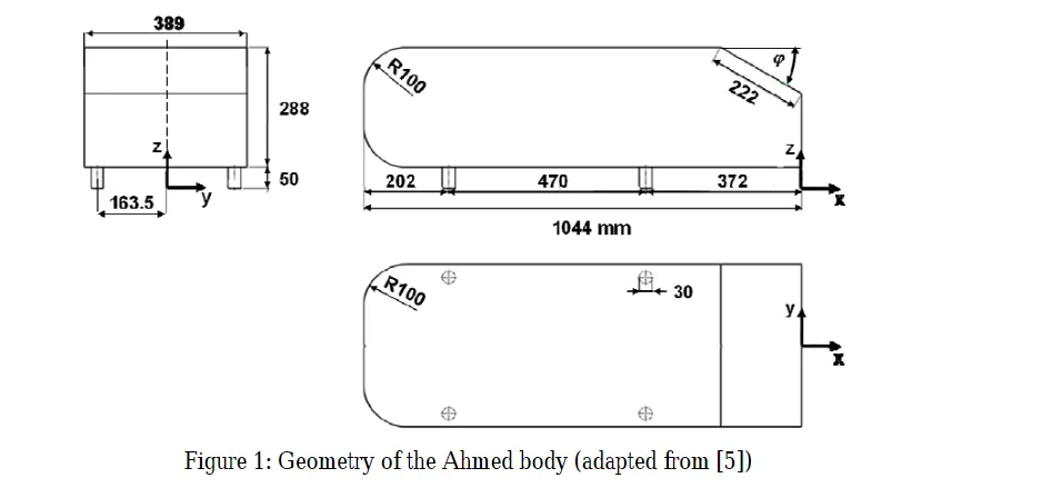
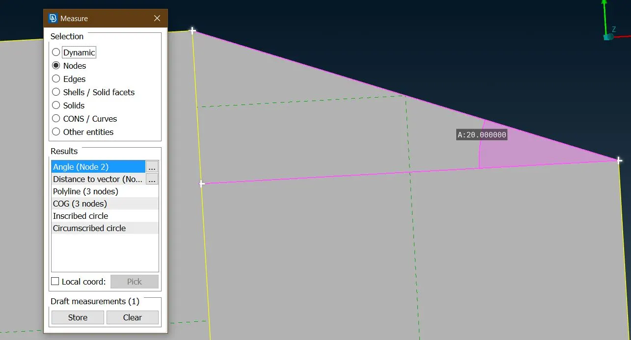
Slant Angle for this geometry = 20 deg
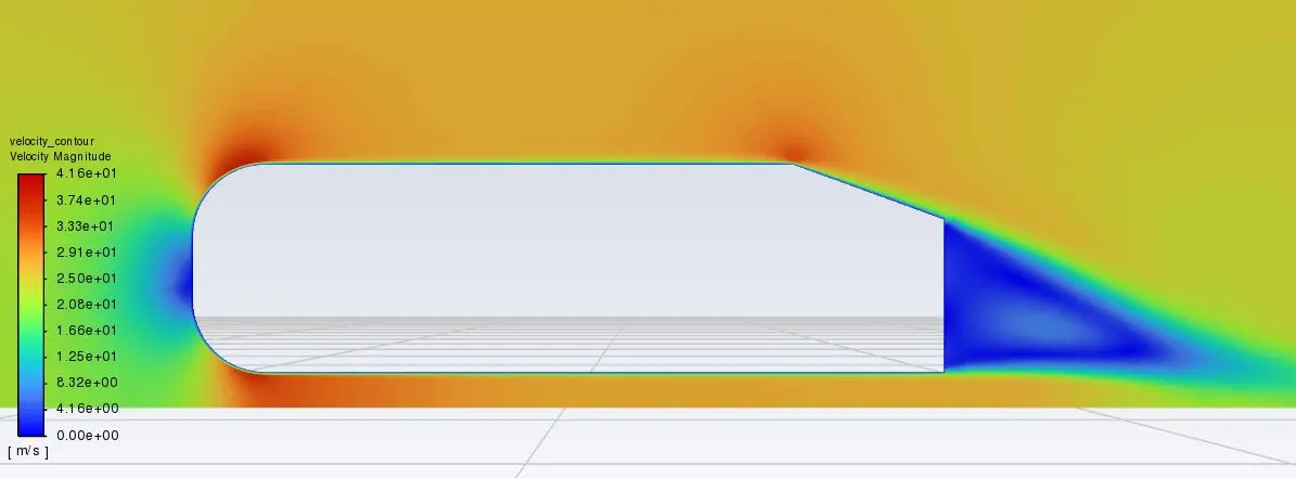
Theory:- When fluid strikes Ahmed's body, the stagnation condition follows and pressure reaches its maximum, then as the flow travels further it reduces as it passes through the first corner, this sets up the favorable pressure gradient which drives the flow and velocity increases. As fluid passes through the top section, it remains constant because of the straight curvature. Then as the fluid reaches the slant, it starts decelerating due to the curvature, to conserve the energy equation the pressure must increase. This leads to the adverse pressure gradient which retards the flow. As flow is decelerating, a point comes where velocity approaches zero, this is the point of flow separation after this if the conditions remain the same, reverse flow occurs. This creates vortices which are regions of low pressure. The presence of these vortices in the wake further reduces the pressure and increases drag on the object.
Solving And Modelling Approach
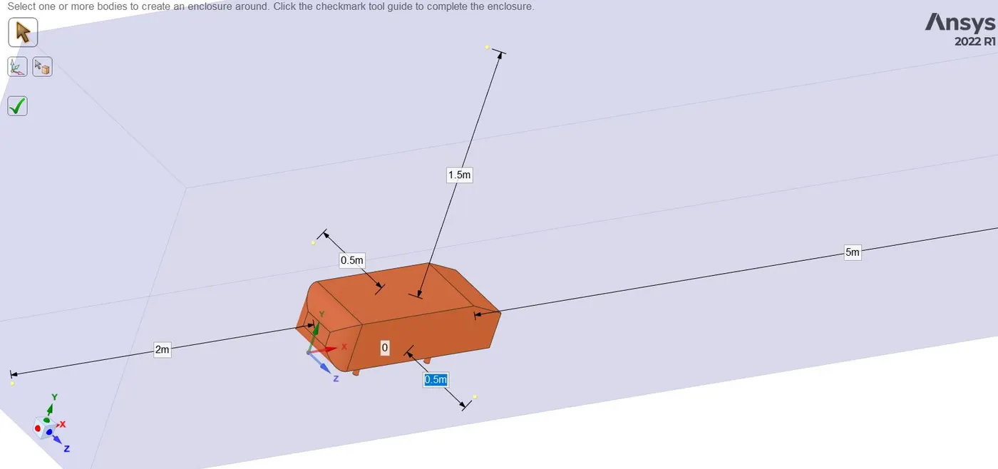
We are going to set up a wind tunnel around the ahmed body
Now we create a sub wind tunnel closer to the body
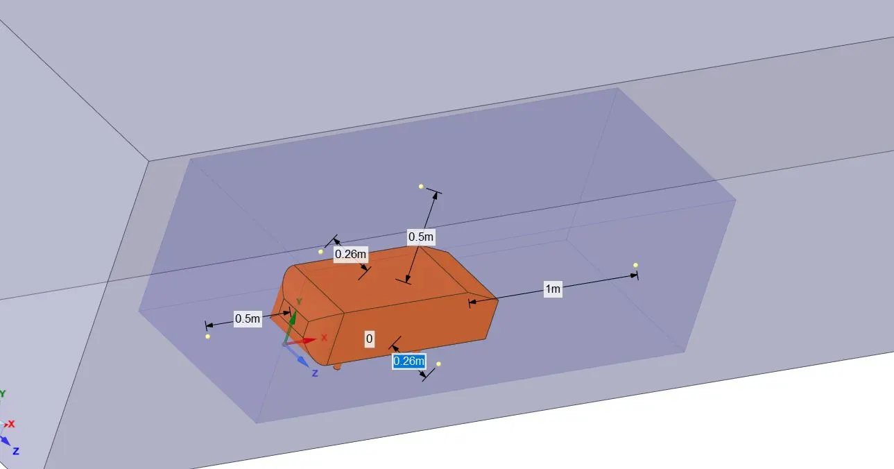
Now this way our wind tunnel is set up.
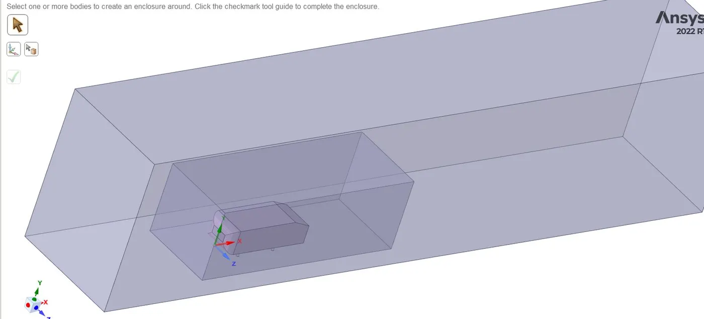
Now we use the split command to have only work with the half of the model
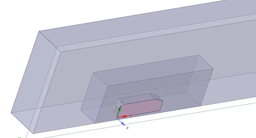
We check for interferance and fix it.
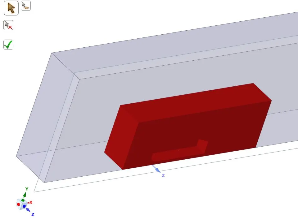
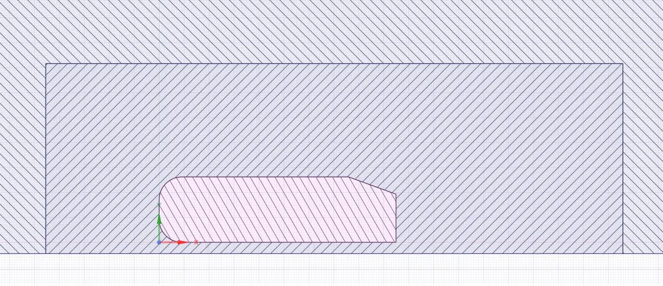
Pre-Processing and Solver Settings
Meshing
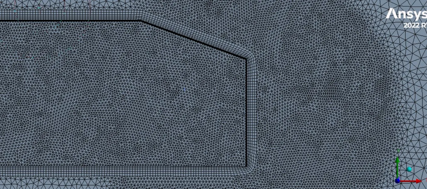
We use the multi zone approach to varry the mesh finer towards the object. This way, around the object where gemoetry is complex elements will be tetragonal and in the outer regions of the wind tunnel we use hexahedral mesh.
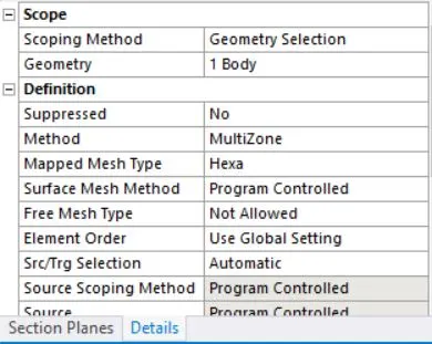
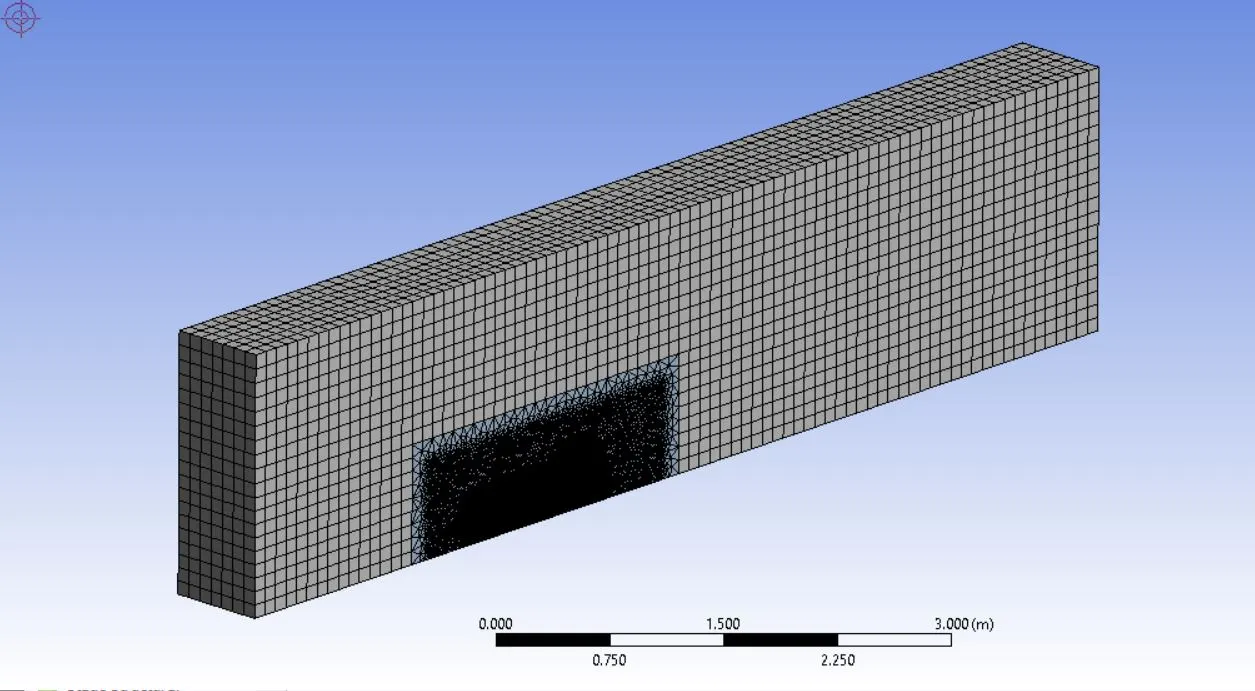
This way mesh gets gradually finer towards the wall
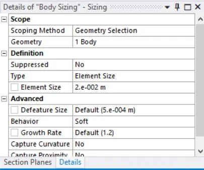
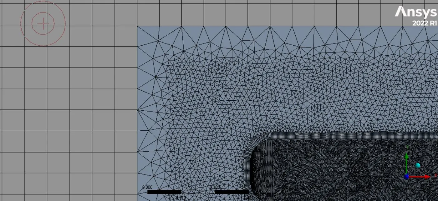
Now towards the wall we employ inflation layers to resolve the boundary layers. We use total thickness method which results in better mesh quality.
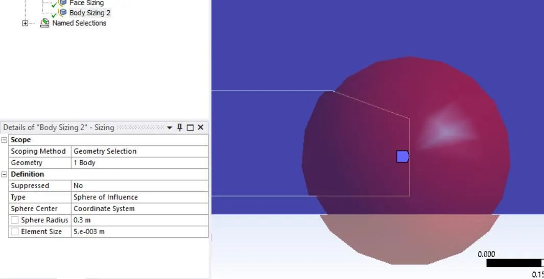
To further refine the mesh in the wake we use a spherical region of influence.
Quality of Mesh
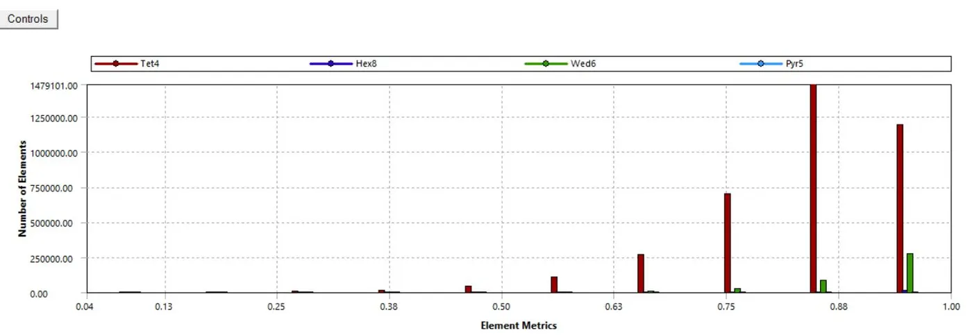
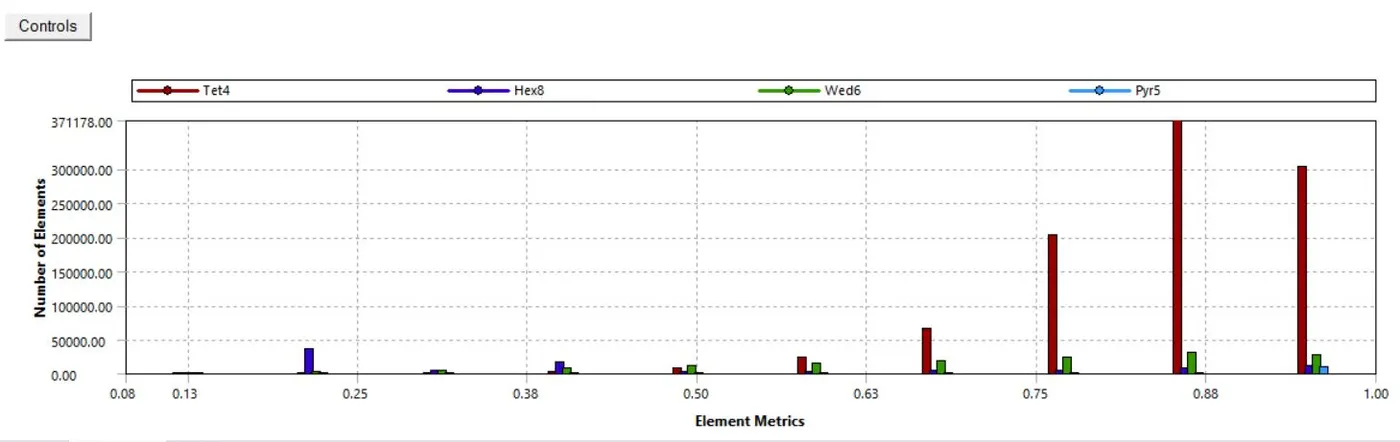
The resulting mesh has a high quality with the following statistics:
Total Number of Elements: 4373279
Total Number of Nodes: 901981
Average Quality: 83.6%
Solver Settings
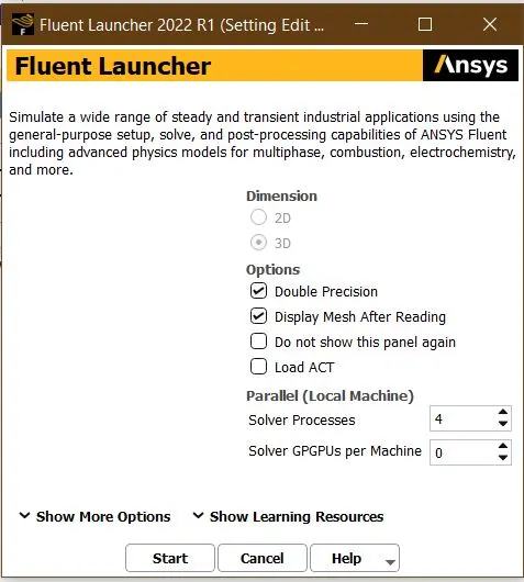
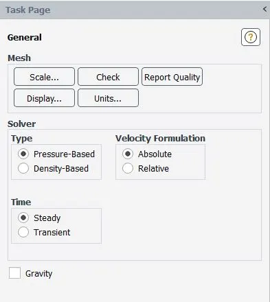
Using pressure based steady-state solver
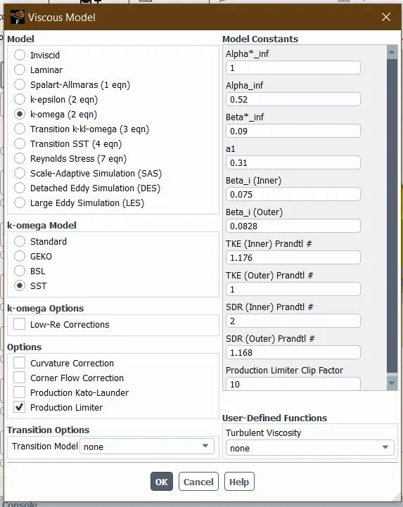
Selection of K- Ω SST as viscous Turbulance model
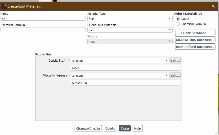
Selection of Material Properties
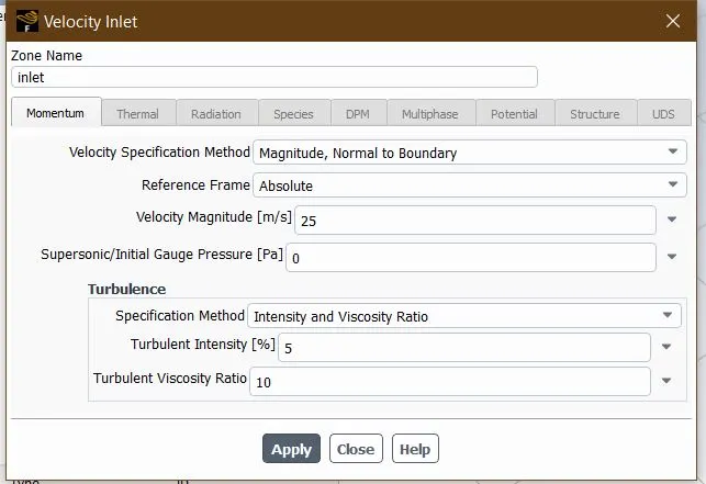
Setting up the Inlet boundary conditions
Setting up the referance values
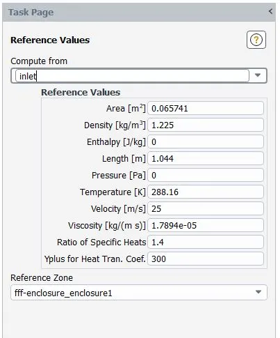
We first run the hybrid initialization and run the steady state solver. The following are the results we obtained:
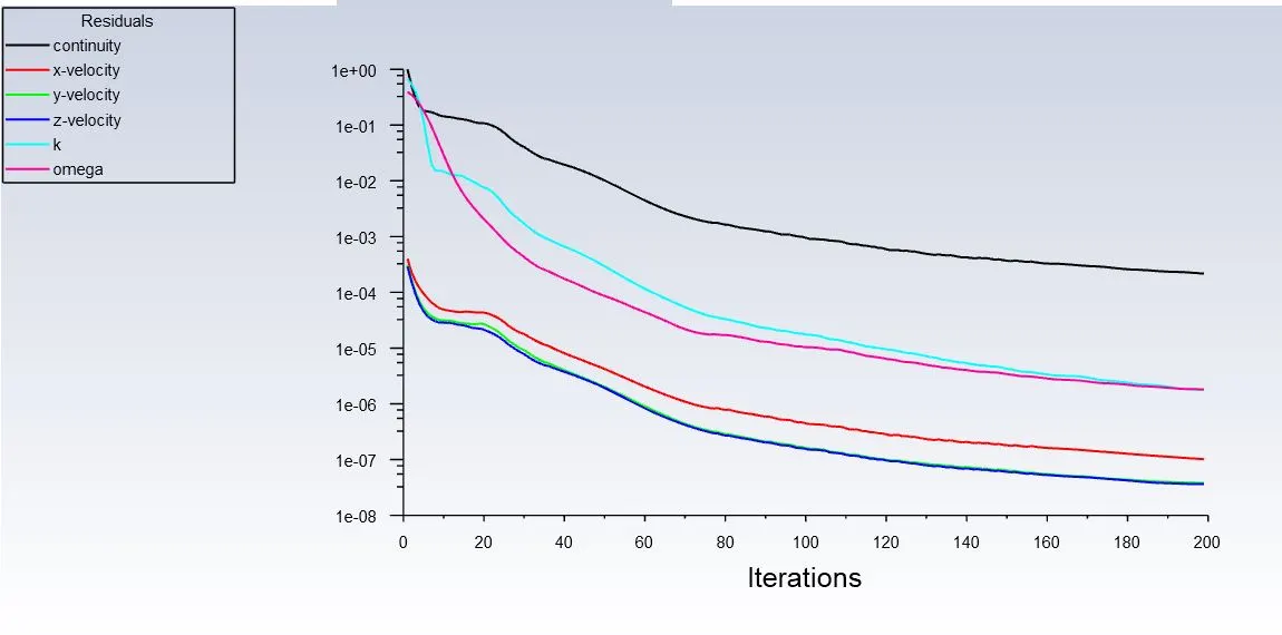
- Scaled Residuals
2. Velocity Contour
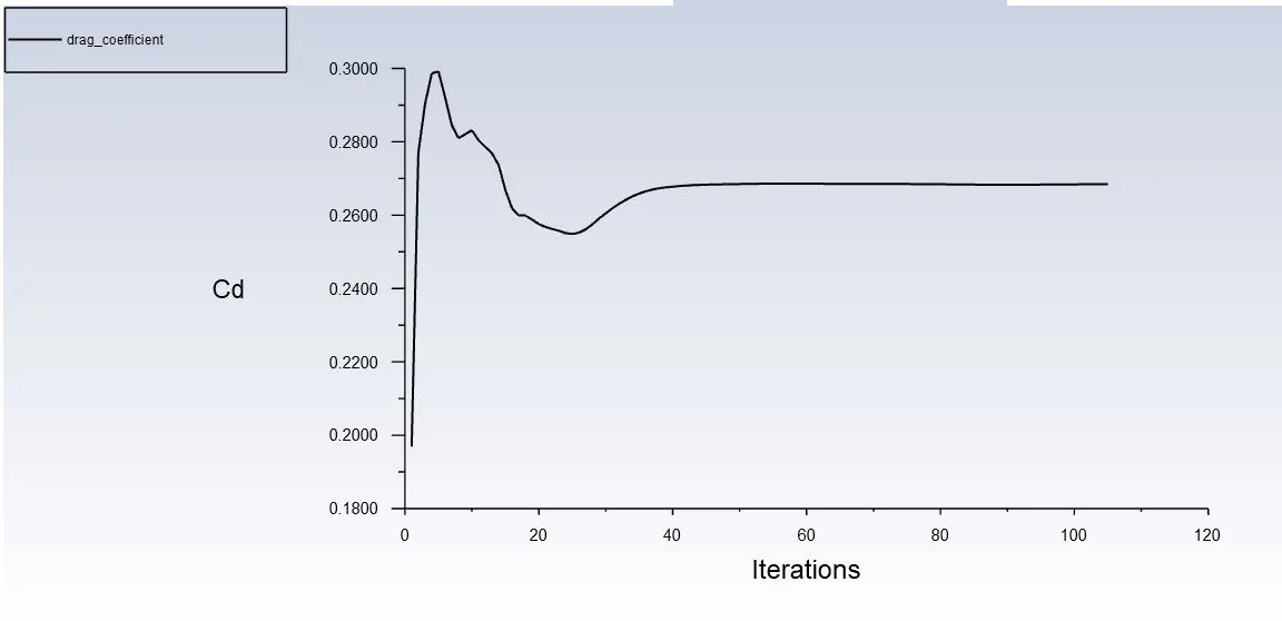
3. Drag Coefficient
Cd= 0.2684
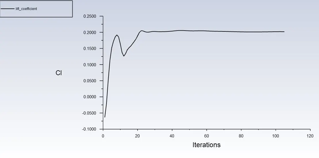
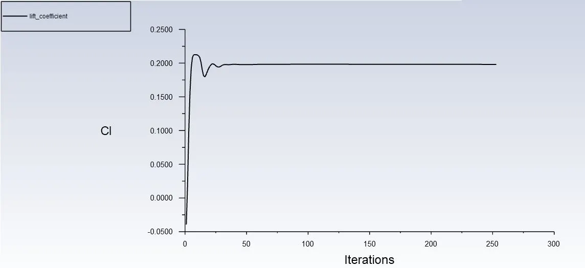
4. Lift Coefficient
Cl=0.20182
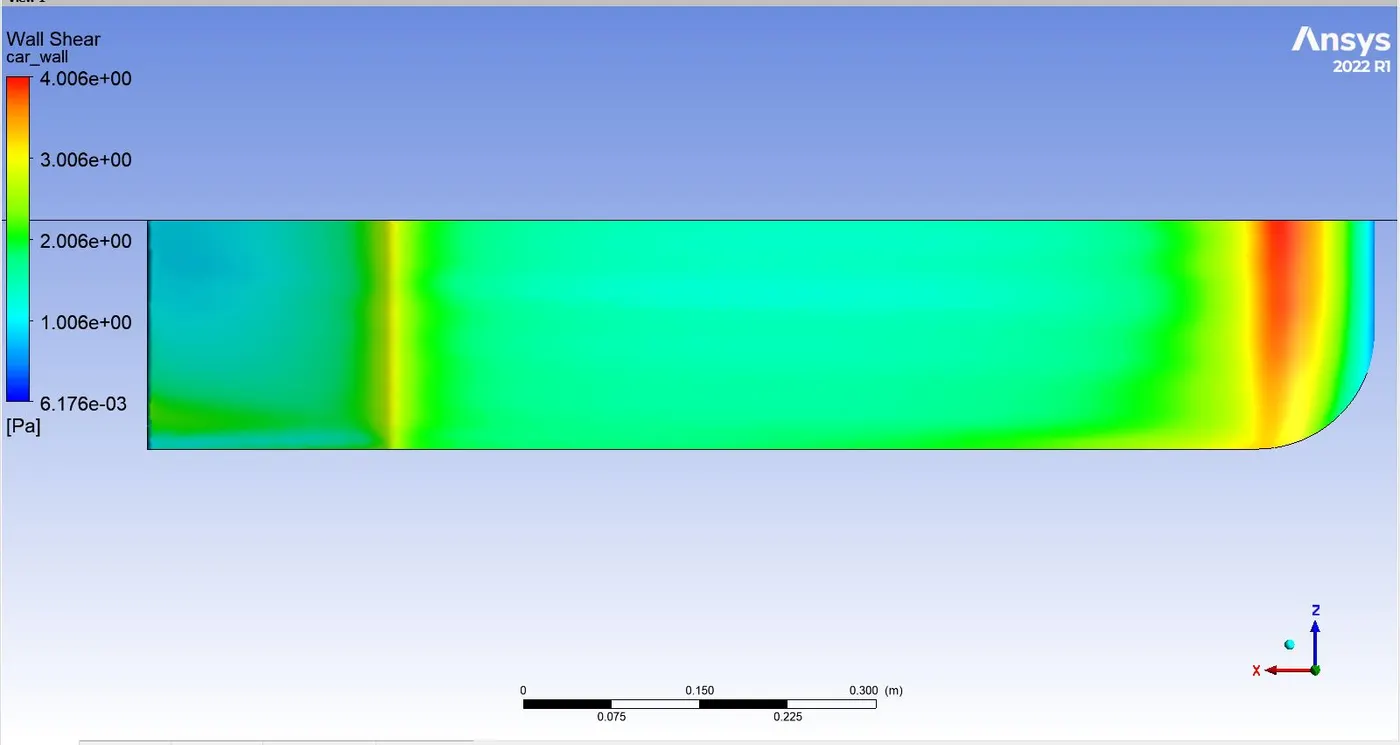
5. Wall Shear
wall shear at cut-plane
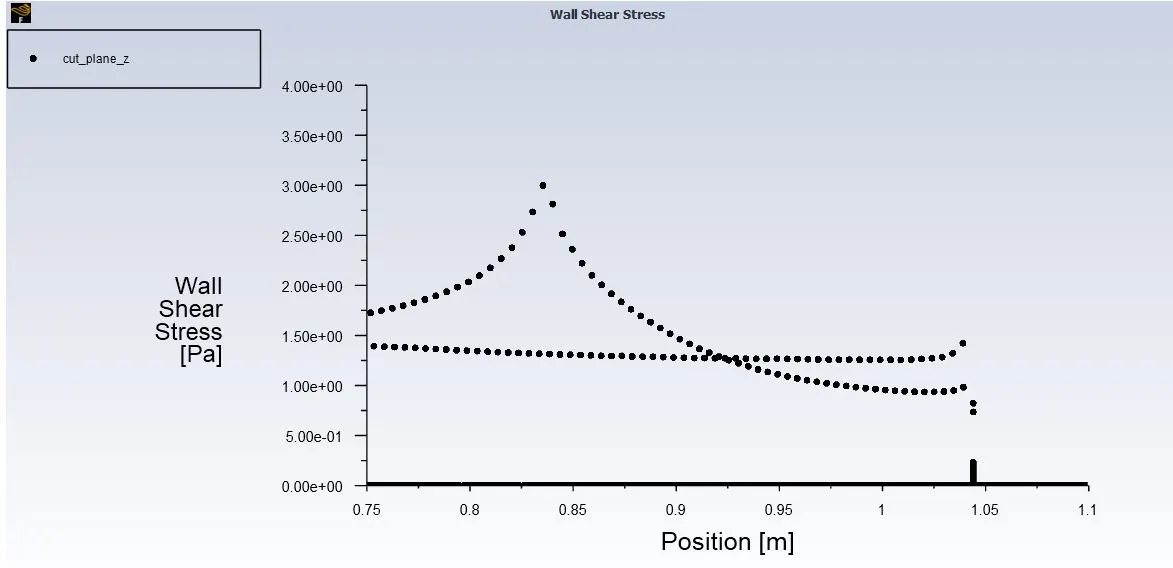
we can see the wall shear stress has close to zero value at x close to 1.044 which is the trailing edge. Thus we can say that flow has saperated at the trailing edge. However the value of wall shear has not gone to negative anywhere near the wall, thus we have no reverse flow around the flow geometry.
Since we don't see flow seperation before trailing edge the higher values of Wall Y+ can lead accurate results since the corrections of U+ and Y+ will not deviate significantly.
6. Wall Y+
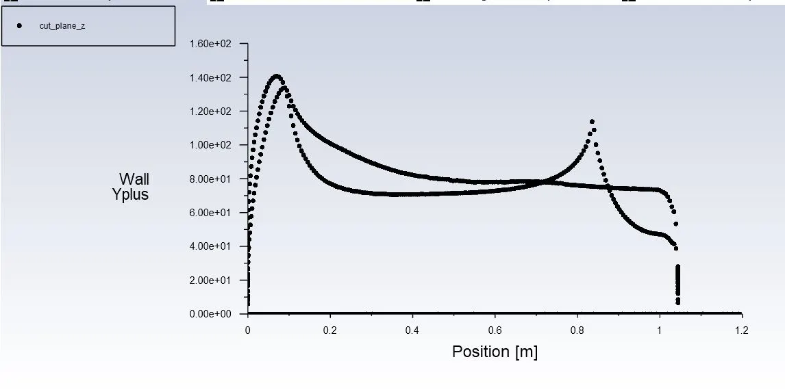
value of Y+ at the trailing edge is around 40 which is acceptable.
Acceptable range (
Post-Processing
- Wall Y+ over the wall.
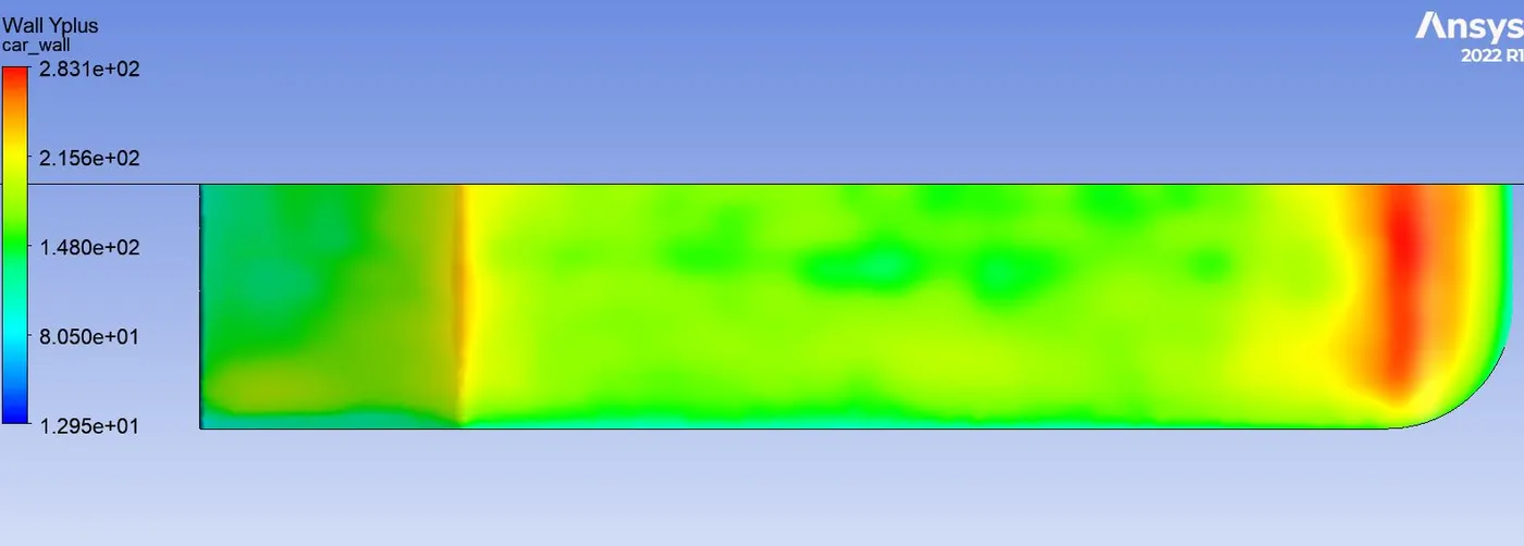
We can see that wall Y+ is in the acceptable range
2. Wall shear stress
 ]
]
We can clearly see as the stant begins, value of shear stress starts decresing since velocity gradient is dimnishing due to adverse pressure grsdient. But no where on the wall we see a zero or negative value of wall shear stress, this resonates to our prior claim that flow is not seperating until the trailing edge where close to zero values are noticable.
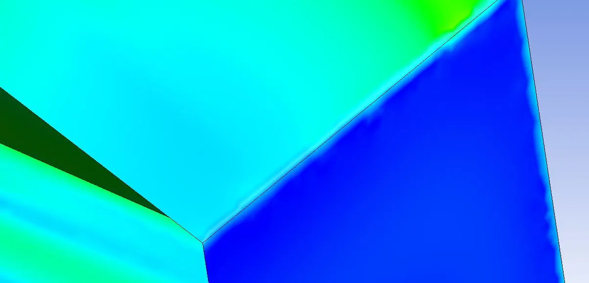
3. No flow around the rear of Ahmed body.
4. Vector plots super-imposed on Velocity contour
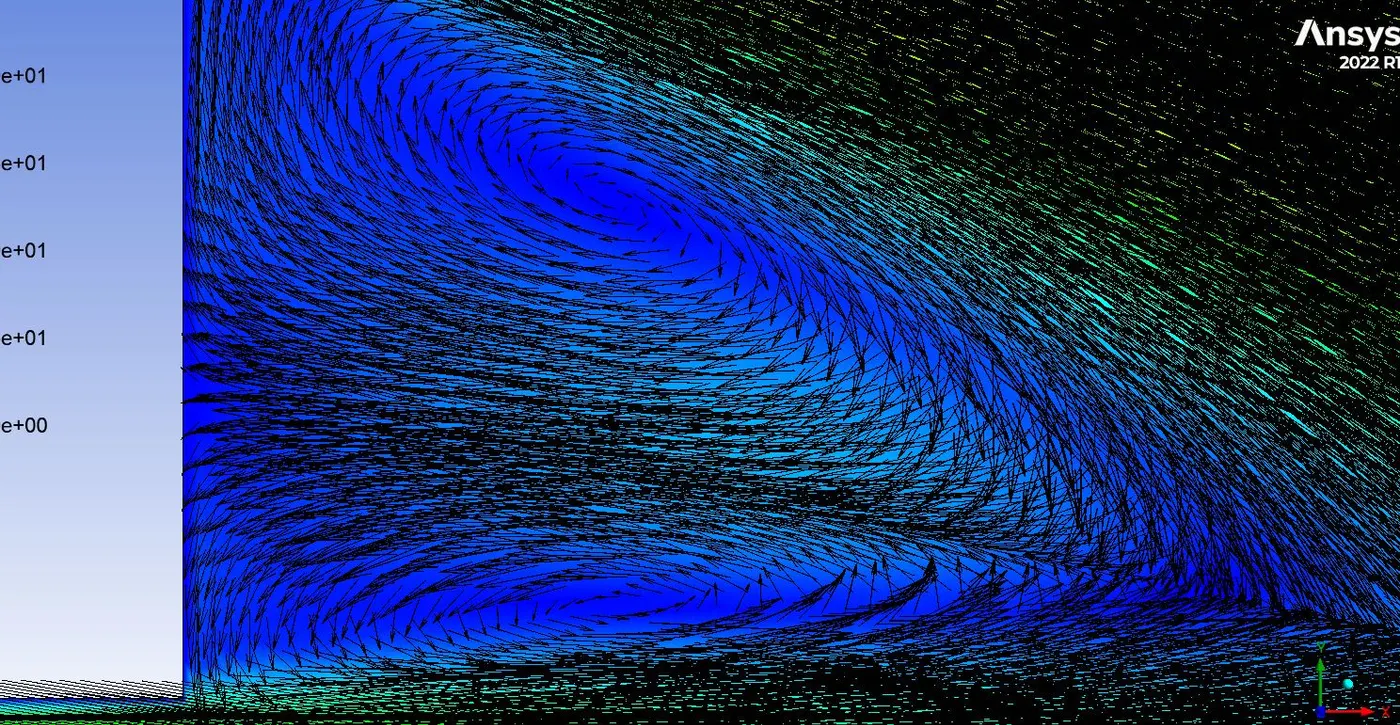
When finally the flow seperates after passing through the trailing edge, the velocity above has higher value and will indue rotationality to the fluid leading to vortex formation. The vortex are expected to develop on both top and bottom regions of the ahmed body and can be visualized using vector plots.
Two regions of contra-rotating vortices, here vecotr plots are superimposed on velocity plots and we can see that the velocities at the centre of vortices are negligible.
5. Velocity vector superimposed on Eddy-Viscosity contours
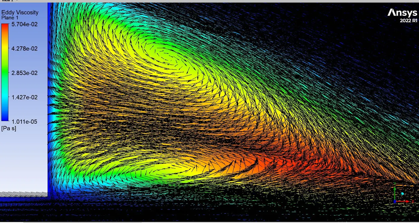
We can see where the interaction between the two vortices is maximum, eddy viscosity is maximnum (red contours), this shows the region of intense mixing.
6. Wake behind the Ahmed Body
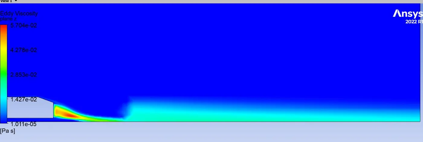
Eddy viscosity is clearly visible far behind the ahmed body, this shows that the turbulent wake has far-reaching effect.
7. Plotting Lines at various locations
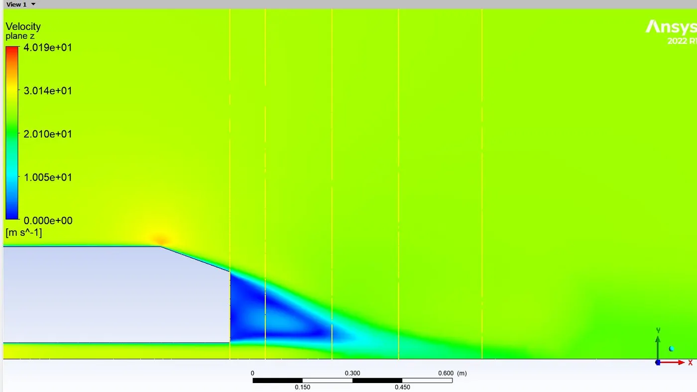
We will observe from the data collected by the lines, how velocity is varying at various locations in the wake
8. Plotting u=f(y) for for the lines
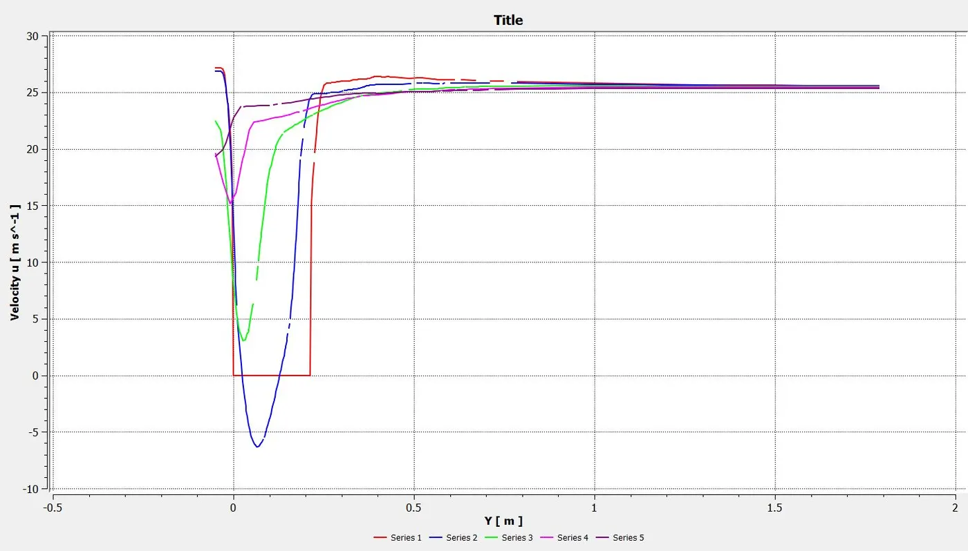
8.1 For line 1 which is exactly at the rear of Ahmed body
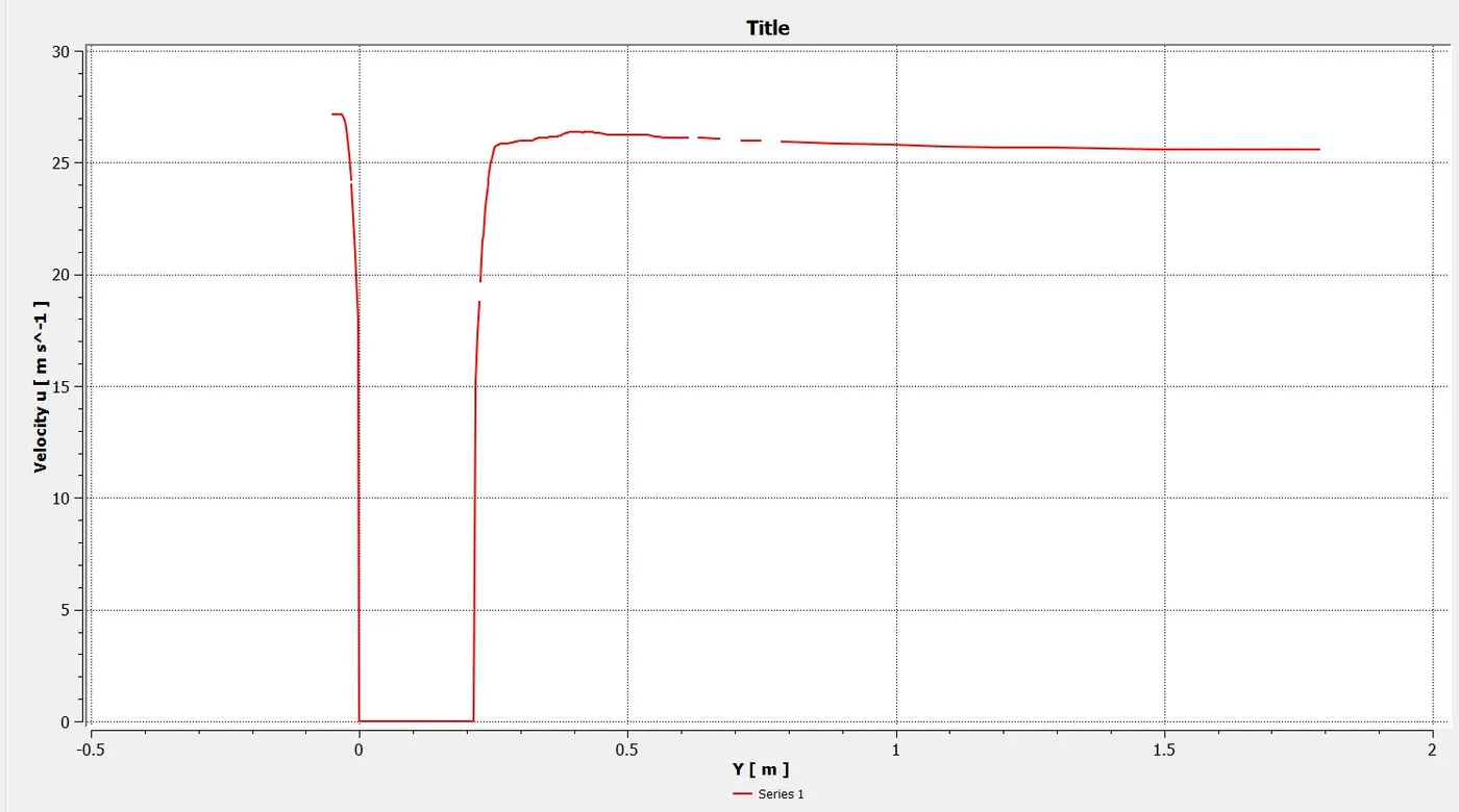
We can see that there are two opposite slopes of velocity (u) seperated by some distance of zero velocity. The zero velocity is the rear of ahmed body
where no flow occurs around the wall. When Y is negative that is the lower region of ahmed body and velocity gradient is negative and y over the trailing edge
shows positive velocity gradient.
8.2 Line 2 and 3
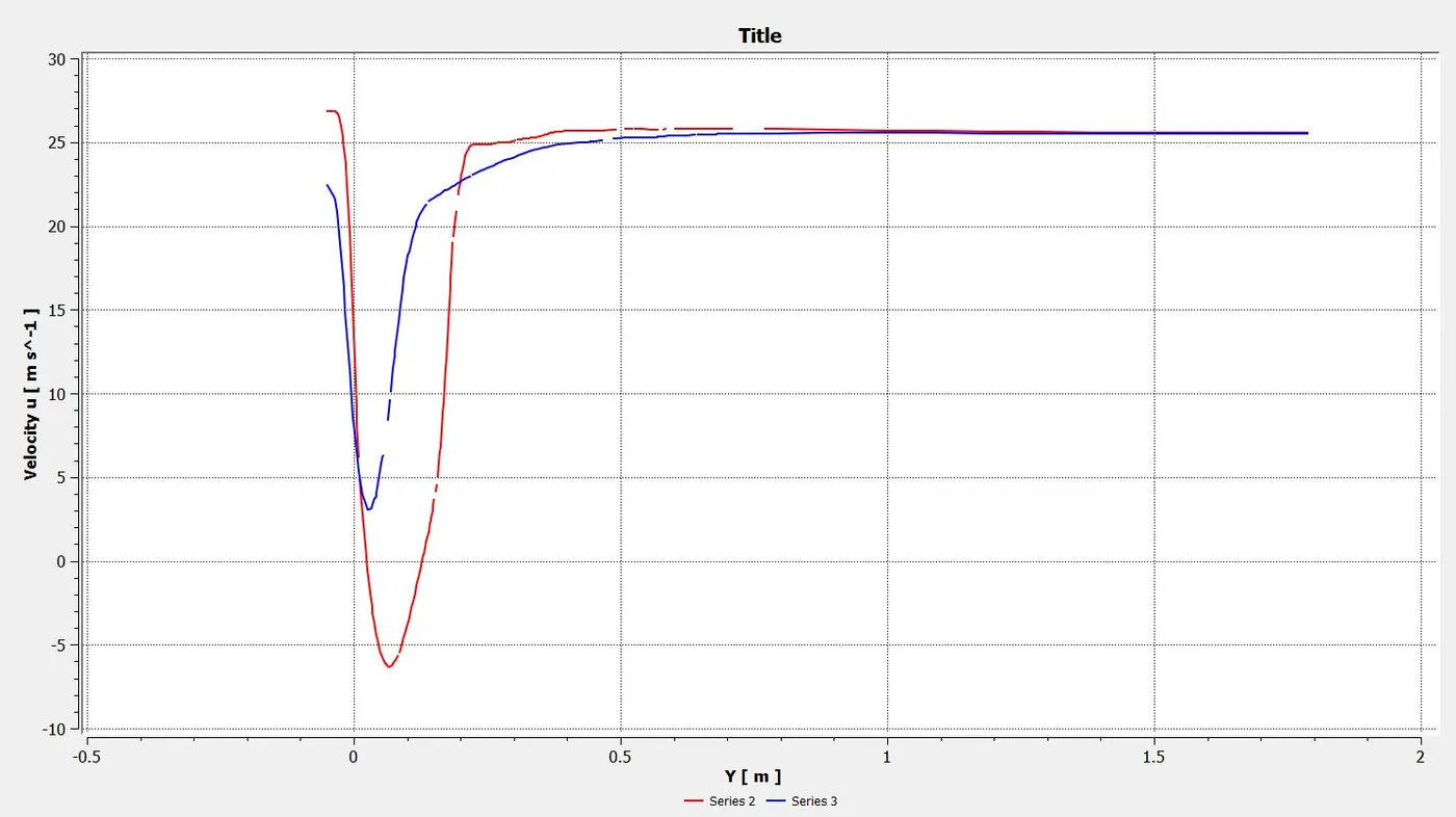
As we move further in the wake the velocity profile is quickly switching the slope from (-) to (+). this is because the region of contra rotating vortices
is shrinking or turbulent dissipiation as a result of eddy viscosity comes into play.
8.3 line 4, 5 and 6
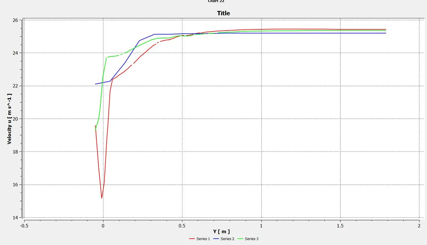
As we move further down the wake, the eddy viscosity decreases and thus the vortices have resoloved into each other and the region where the
eddy viscosity contours shrinks, the turbulent dissipiation has commensed and a developed velocity profile with + gradient is seen (green line)
8.4 Summing all lines into a single graph
9. Investigating the 3 dimensional variation of flow properties in the wake.
Velocity contour at the plane of symmetry Velocity contour at the lateral most plane
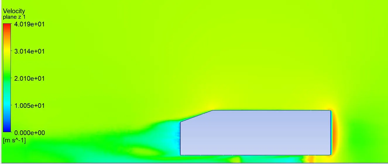
The velocity contours are significantly different for the mid plane and the outer most side of the Ahmed Body, this clearly shows us that the wake is varying
in the space.
Velocity contour at the plane of symmetry Velocity contour at the lateral most plane
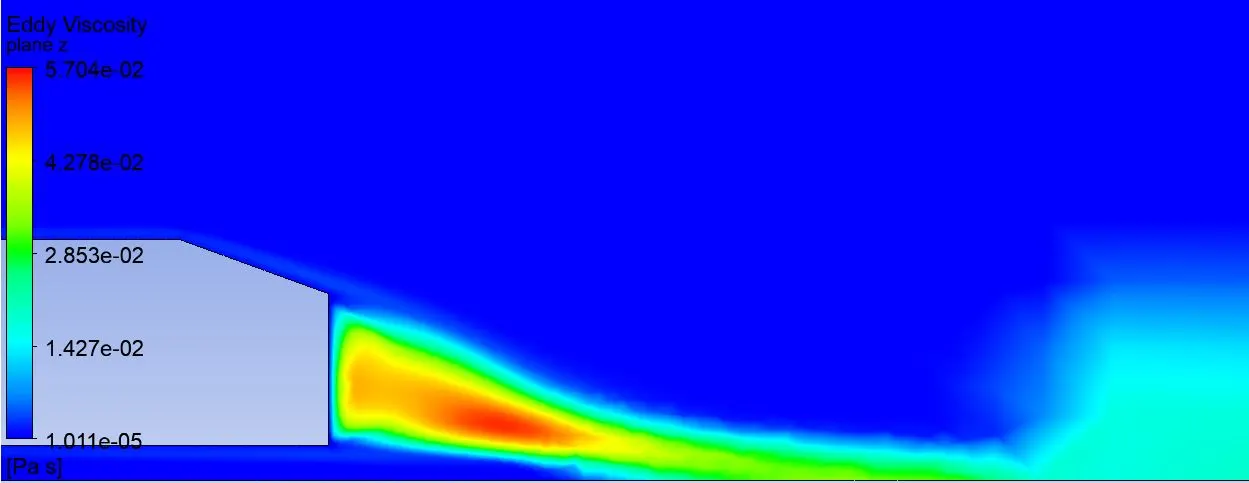
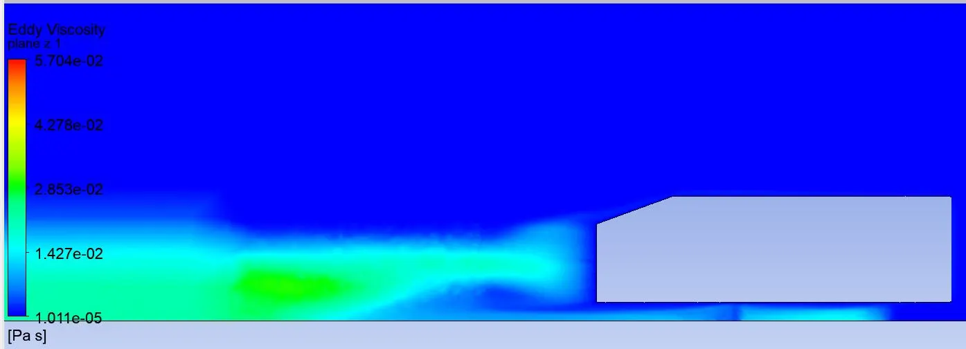
We can clearly observe that the eddy dissipiation which results from the vortices interaction is very high at the plane of symmetry, and it continuously decreases down the wake,
However, for the lateral plane which is located at the side of the Ahmed body, eddy viscosity is minimum and there is a slight increase down the wake. We can claim from here that the
magnitude of eddies is maximum at the plane of symmetry and then it decreases in the lateral direction.
Velocity vector at the plane of symmetry Velocity vector at the lateral most plane
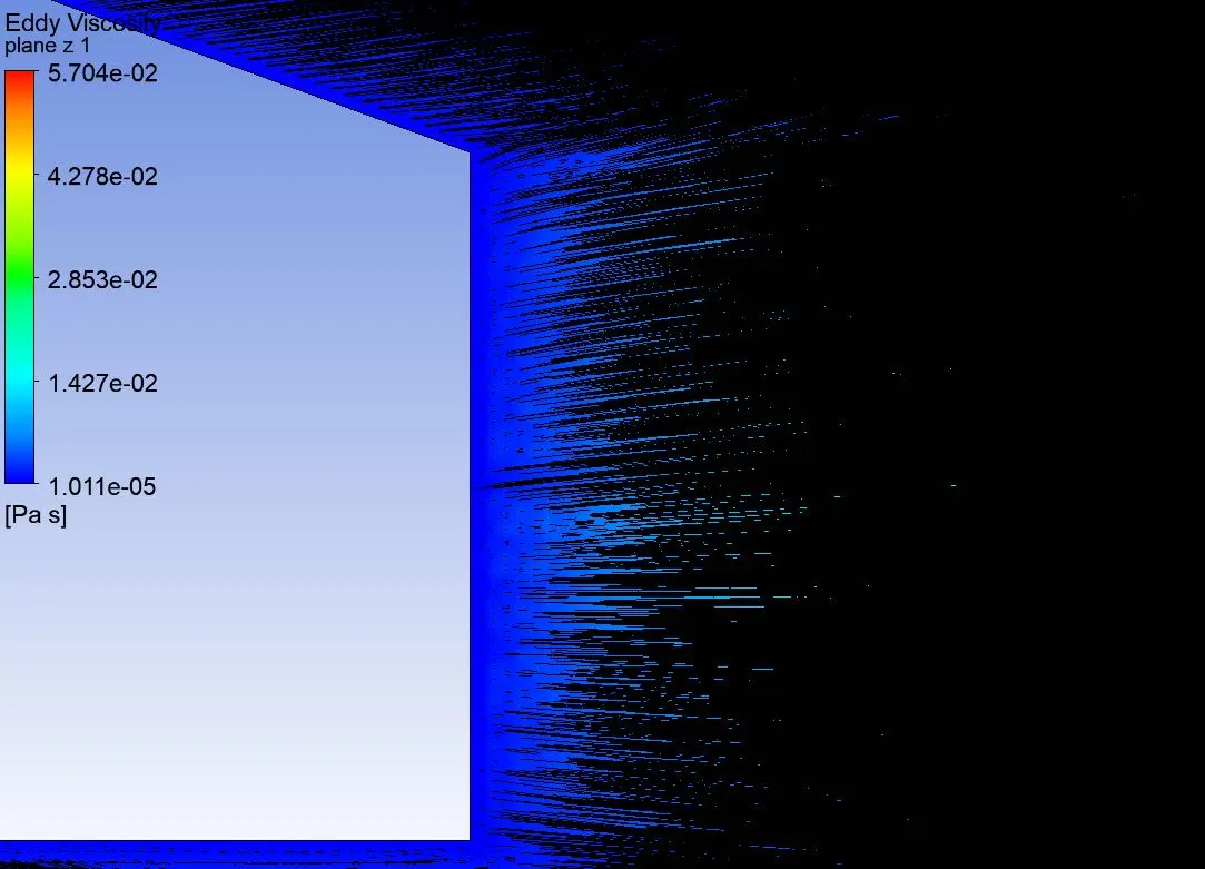
As we can see there are no vortices at the lateral most plane, thus eddies start decreasing from the plane of symmetry in the lateral direction and the lateral most plane, they
vanish completely. But these are longitudinal vortices, at the lateral sides of ahmed body we have horse shoe vortices that develop.
Velocity vector at the plane of symmetry down the wake Velocity vector at the lateral most plane down the wake
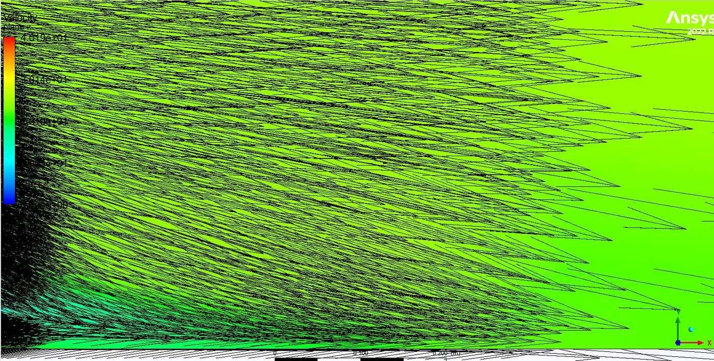
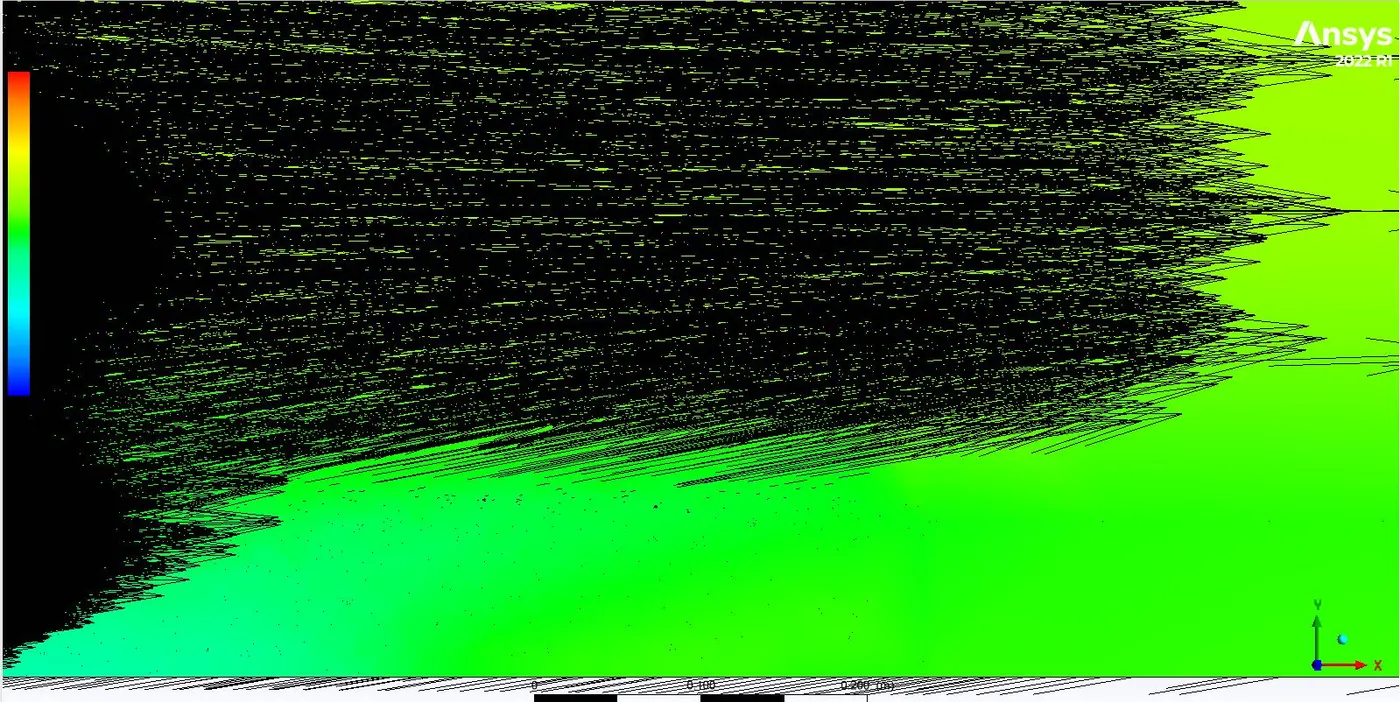
To investigate the further wake at these plane we can clearly see that we need more elements down the wake.
Validation of Results
 [2]
[2]
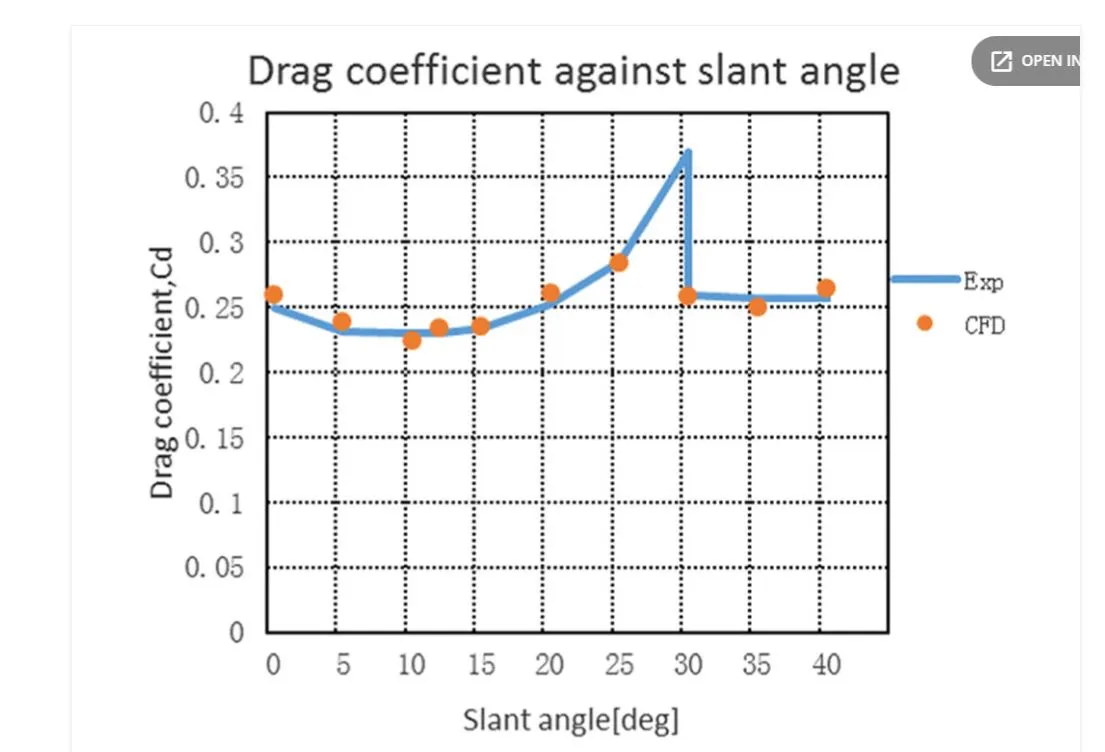
following the Experimental data, we have Cd = 0.25 at 20 degree slant angle and Reynolds number of 4 million
It is well known that Cd of Ahmed body increases with Reynolds number upto stant angle of 30 degrees from there it reduces because flow seperates prior to trailing edge.
 [3]
[3]
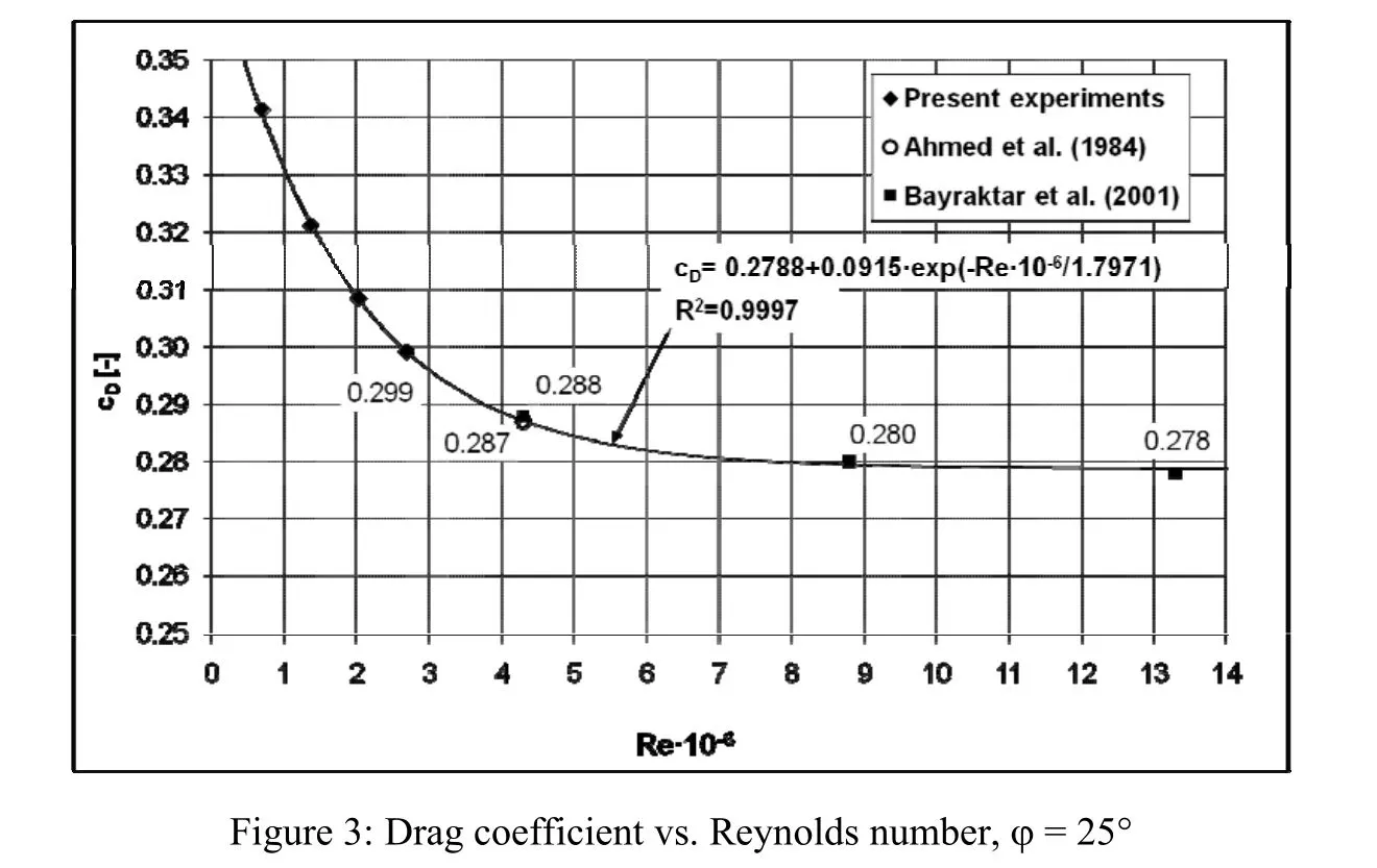
this data is for slant angle of 25 degrees and shows Cd decreasing with respect to reynolds number
Thus Cd for our analysis must be greater than 0.25
Cd from Analysis = 0.2684
which is in good agreements.
Mesh Dependence Test
We will run now different meshes with increasing number of elements to see where the Cd and Cl is getting independent of Mesh size.
1. Coarse Mesh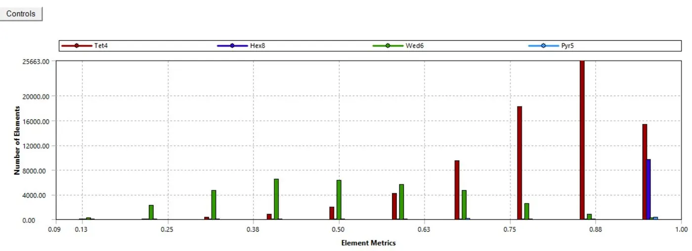
Mesh Quality
Coefficient of Drag Cd=0.317
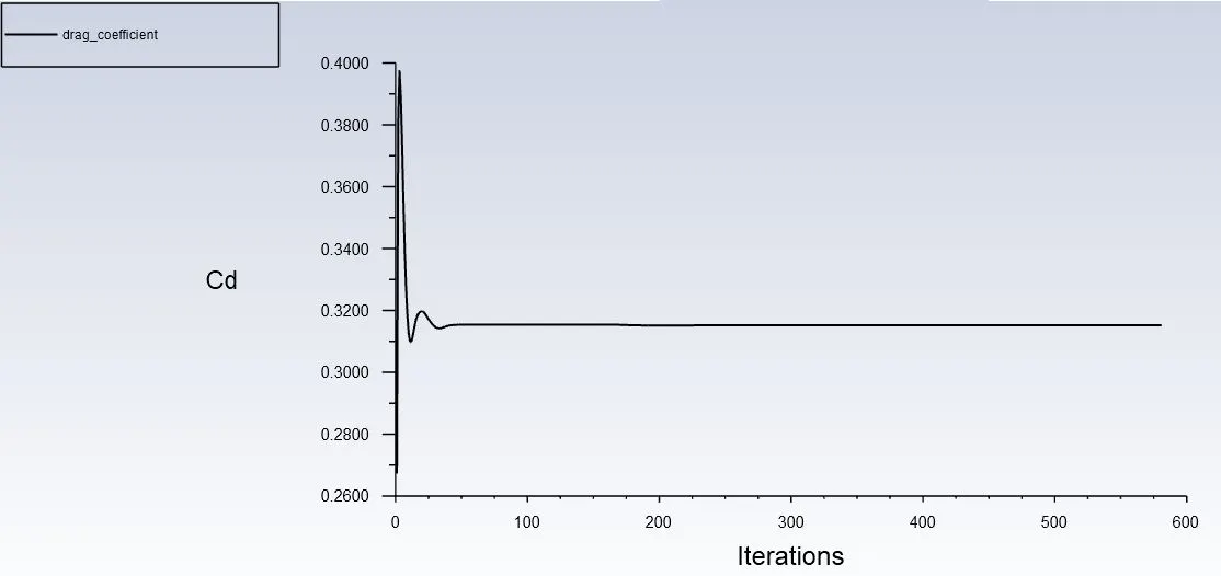
Coefficient of Lift Cl= 0.213805
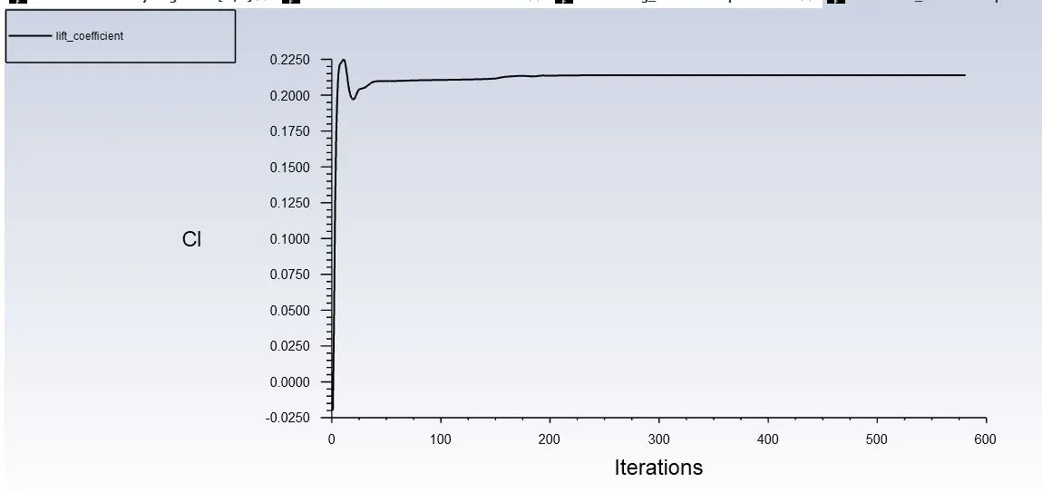
2. Fine Mesh
Mesh
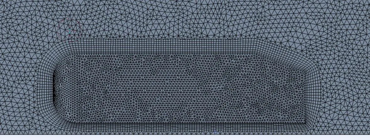
Quality of Elements
Coefficient of Drag Cd=0.295
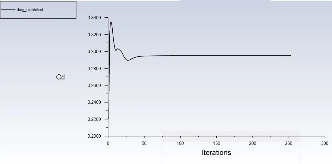
Coefficient of lift Cl=0.19813
3. Refined Mesh 1
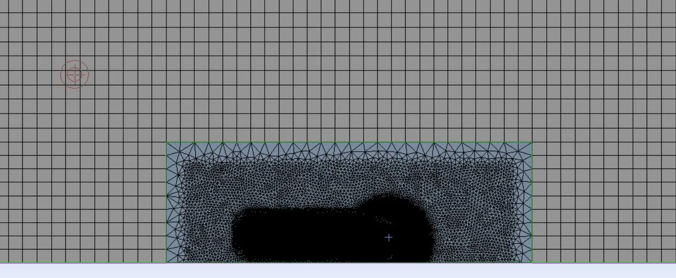
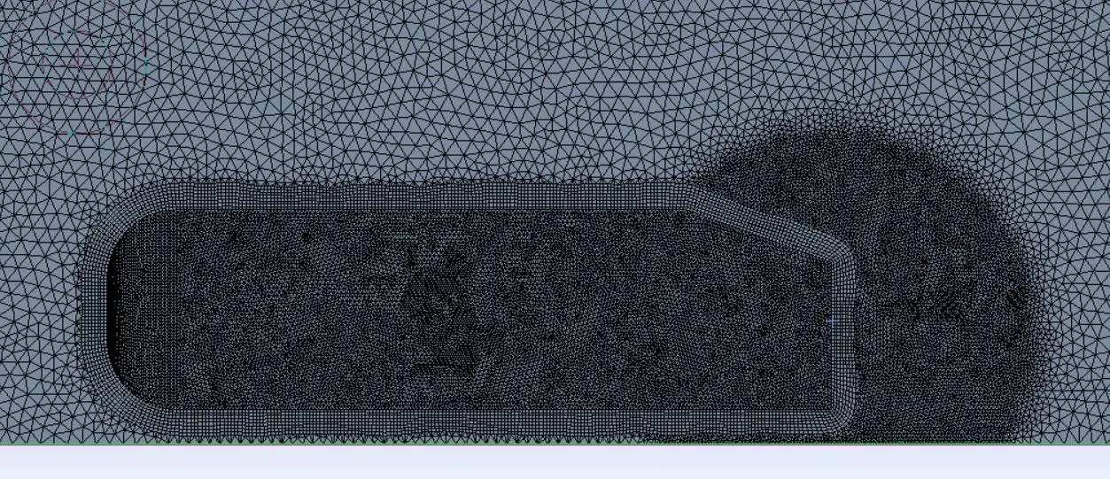
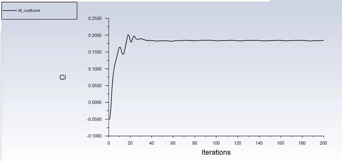
Element Quality
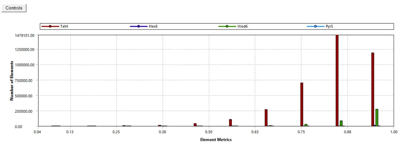
Coefficient of Drag Cd=0.2817
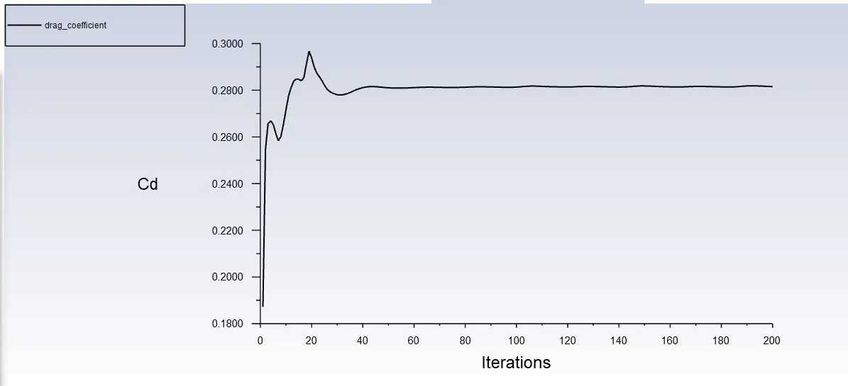
Coefficient of Lift CL=0.186305
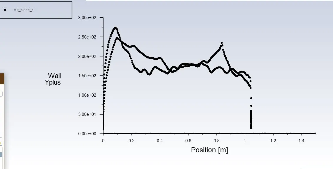
Wall Y+
Refined Mesh with First layer thickness
Element Quality
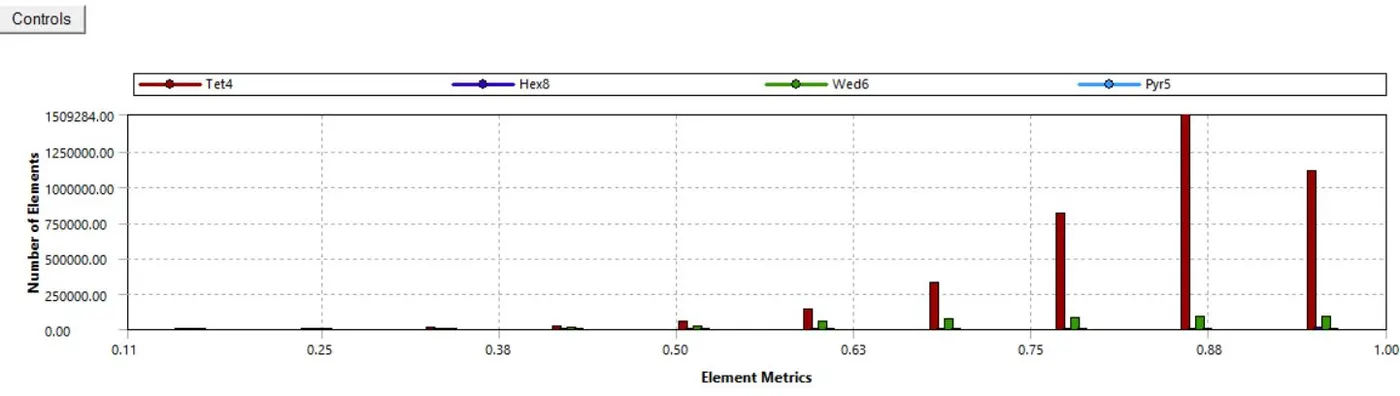
Incorporating first-layer thickness method over total thickness reduces the mesh quality but it allows us to better control the first layer thickness value which
is cruitial for Y+ value
Coefficient of drag Cd= 0.268
Coefficient of lift Cl=0.20182
Wall Y+
Using First layer thickness lead to refuction in Y+ from 125 to 40 (nearly), and it did affect the Cd as expected and resulted into a value closer to the
expected results, this can be because of y+ in better rangle of values that was done with first layer thickness method.
SUMMARY
| Mesh | Number of Nodes | Number of Elements | Avg. Element Quality % | Cd | Cl |
| Coarse | 44088 | 119251 | 73.69 | 0.1352 | 0.2138 |
| Fine | 333967 | 1201874 | 81.064 | 0.295162 | 0.19813 |
| Refined 1 | 871479 | 4195169 | 84.73 | 0.2817 | 0.1863 |
| Refined 2 | 901381 | 4373279 | 83 | 0.268 | 0.201 |
Results from Experimental DATA:
Cd >0.25
Thus Resfined 2 mesh is the best solution. Although the more pragmatic approach will be to further refine the mesh and establish a Cd which doesn't varies with mesh but our computational capacity limits us in this regard.
Conclusion.
- Ahmed body offers us a simple geometry to investigate flow behaviour which resonates well with actual automobiles.
- For our analysis the slant angle is 20 degrees, and thus the ahmed body behaves like a square-back vehicle where flow does not seperates prior to trailing edge.
- The flow behaviour in the wake is complex and varies 3 dimensionally in the space.
- The inword longitudinal contra-rotating vortices are strongest at the plane of symmetry and decreases in strength laterally.
- At the sides of ahmed body there is presence of Horse shoe vortices.
- Due to vortices behind wake the pressure there is lower, this is because the centre of vortices is a region of low pressure, this leads to drag due to shape or form and is called Pressure Drag.
- Analysing the eddy viscosity we observe that the complex turbulent wake extends much further down the wake, this suggests to us that we need to increase the size of our wind tunnel particularly in the rear of ahmed body.
Referance
- [Ahmed et al., (1984)] S.R. Ahmed, G. Ramm and G. Faltin, Some Salient Features of the Time-Averaged Ground Vehicle Wake, SAE Technical Paper 840300, 1984
- Tian, J., Zhang, Y., Zhu, H., & Xiao, H. (2017). Aerodynamic drag reduction and flow control of Ahmed body with flaps. Advances in Mechanical Engineering, 9(7), 168781401771139. doi:10.1177/1687814017711390
- Experiments and numerical simulations on the aerodynamics of the Ahmed body
- Flow and Turbulence Structures in the Wake of a Simplified Car Model (Ahmed Model)
- https://help.sim-flow.com/validation/ahmed-body