Week 3 - External flow simulation over an Ahmed body.
AIM
- To perform external flow simulation over Ahmed body and calculate the coefficient of drag for an inlet velocity of 25 m/s.
- Plot velocity and pressure contours.
- Perform grid independency test and it's effect on drag coefficient.
Q1: Describe Ahmed's body and it's importance.
Ahmed Body is a generic car body that was developed by S.R Ahmed to study the airflow around a car. 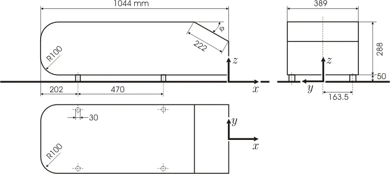
The Ahmed body has the form of a highly simplified car, consisting of a blunt nose with rounded edges fixed onto a box-like middle section and a rear end that has an upper slanted surface, the angle of which can be varied. It retains vital features of real vehicles in order to study the flow fields around it and the related turbulence models which characterizes the actual flow at elevated Reynolds number. The Ahmed body is designed to have a smooth-edged front end with a flat roof and a flat bottom section and an angled back slant which basically acts as the rear window of a car and ending with a vertical base. The
back-slant angle which is commonly designated as ϕ is very critical to the flow patterns which are fashioned at the near wake region and subsequently has an impact on the aerodynamic forces which act on the body.
The Ahmed body is easy to model, it can be effortlessly utilized for researching various properties like turbulence, drag coefficient, wake region, lift forces, velocity magnitude at various regions of the car, magnitude of pressure around the car which helps in determining what will be resistance, fuel efficiency etc. of the car thereby providing designers a clear idea on which region needs to be optimized for better effectiveness.
Experimental results of the flow around the ahmed body is available which can be used to validate the accuracy of the CFD simulation. Once you have a validated CFD setup, you can move forward withe the setup for optimizing the car body since experimantal analysis of the car body with various changes in the geometry is very time consuming and costly. CFD simulation of the geometries is a much more viable option for optimizing the geometry after which an experimental analysis of the final design can be done. This helps manufacturers in reducing the cost of development of the car.
Q2 : Explain the reason for negative pressure in the wake region
The wake is the region of disturbed flow (often turbulent) downstream of a solid body moving through a fluid, caused by the flow of the fluid around the body
.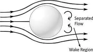
Reynolds number is the ratio inertia force to viscous force. As the reynolds number increases, the inertia forces of the fluid particles increases. This causes flow to seperate from the boundary of the body by overcoming the viscous friction acting on the fluid by the body. The pressure inside the wake region remains low as the flow separates and a net pressure force (pressure drag) is produced. The flow sepration causes drag force on the body which is indicated by the negative pressure. The goal while designing the car is to minimize the drag force acting on the car to improve the efficiency of the car. Flow separation should be minimized while designing the car.
Q3. Explain the significance of the point of separation.
The point on the body where the boundary layer lifts off the surface is called the separation point. When the air flow separates off the surface, the pressure drag usually increases.
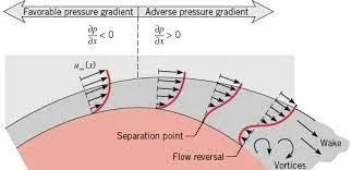
In many problems it is necessary to know the boundary layer whether laminar or turbulent, will separate from the surface of a specific body and, if so, where the separation will occur. That is quite important, since in many design problems, such as those of the design of hydrofoils or airfoils, it is necessary to avoid flow separation in order to obtain low drag and high lift.For two-dimensional steady flows, the separation point is defined as the point where the wall shear stree τw is equal to zero. Predicting the point of separtion of fluid flow will help in designing more efficient bodies. It is always advisable to prevent separation of flow on the body.
Procedure
- Import the Ahmed geometry into spaceclaim.
- Ensure the units in spaceclaim are in meters.
- Once the geometry is imported, our goal is to create an enclose volume around the body to simulate the flow around the body.
- Since the body is perfectly symmetric, we can use the split body command and delete half of the body.
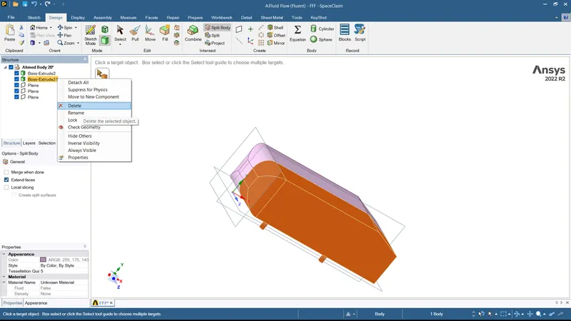
- Use Prepare>Enclosure function to create an enclosure around the body.
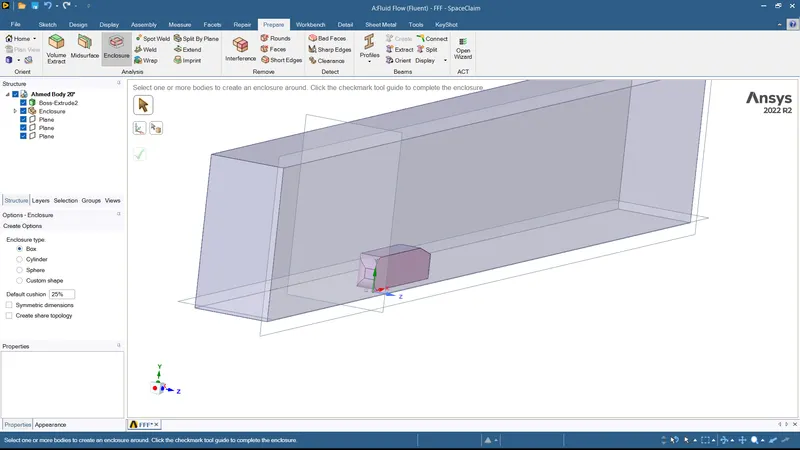
- Check for interference.
- Supress the Ahmed body for physics.
- Close the spaceclaim workbench and open meshing.
- Create Named selections for the geometry: Inlet, Outlet, Symmetry and car wall.
- Once this is done create a default mesh for the geometry.
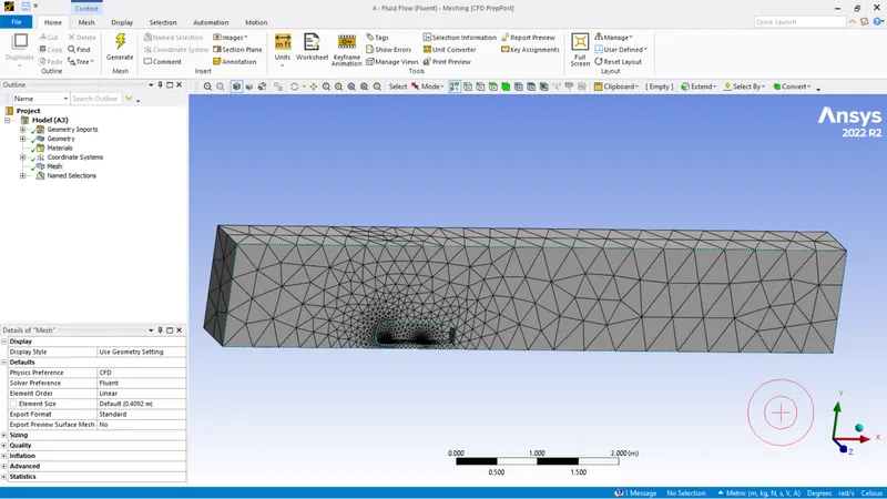
Default mesh size 0.4092 Nodes 8454 Elements 41923 - Close the mesh module and open setup with double precision..
- We will run a baseline simulation with default mesh and once a general idea is obtained we can move onto further refining the mesh and simulation.
| Solver | Pressure based since Mach number below 0.3 |
| Velocity Formulation | Absolute |
| Time | Steady |
| Energy | On |
| Viscous Model | Standard K-Epsilon with standard wall function |
| Material | Air |
| Cell Zones | Air |
Boundary Conditions:
| Inlet | Velocity inlet; Velocity Magnitude : 25 m/s; Thermal : 300 K |
| Outlet | Pressure Outlet; Gauge pressure : 0 Pa; Thermal : 300 K |
| Car_Wall | Stationary no slip wall |
| Symmetry | Symmetry |
Initialize the solution with hybrid initialization.
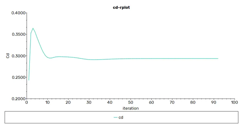
Create velocity and pressure contour of the simulation and monitor coefficient of drag.
Run the solution for 500 iteration.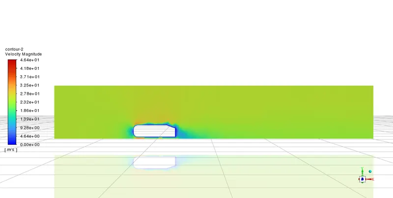
Based on the initial velocity contour, we can create a second enclosure zone near the Ahmed body to better capture the results.
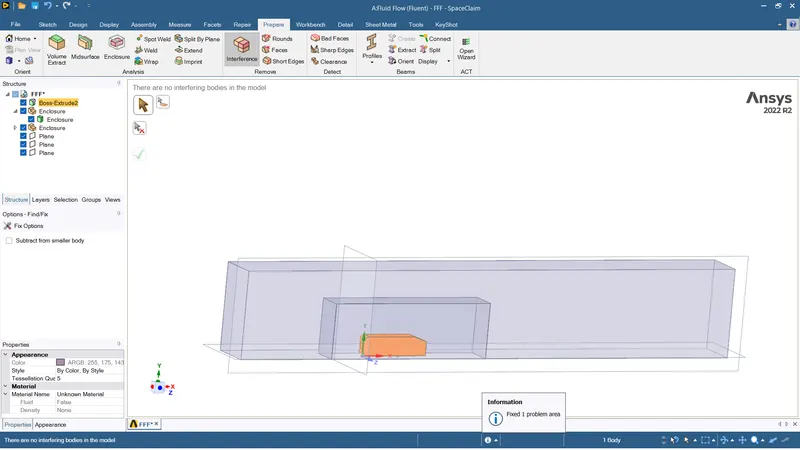
Once the enclosure is created we can move onto the meshing module to refine the mesh.
Ensure that Share topology is kept to share so that these volumes can exchange information with each other.
Open the meshing module.
Multizone meshing for the outer volume with an element size of 150 mm was given to get a structured mesh outside.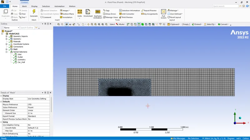
Sizing of 150 mm was given to inner volume and 40 mm for ahmed body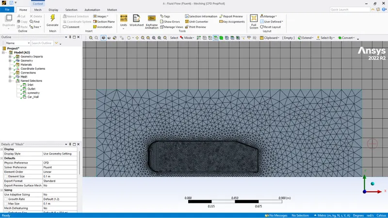
Inflation layer with total thickness of 12.5 mm was given to the ahmed body and leg sizing was kept as 5 mm 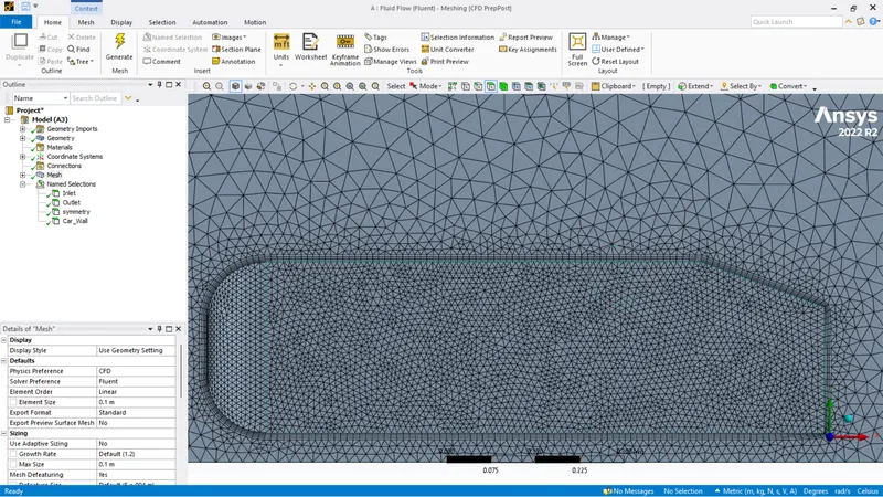
The boundaries were named and setup was opened with double precision.
Literature survey shows tha K-omega SST was the better viscous model for simulating flow around Ahmed Body.
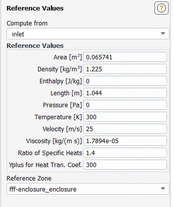
Reference value was updated after calculating the projected area.
| Solver | Pressure Based |
| Velocity formulation | Absolute |
| Time | Steady |
| Energy | On |
| Viscous model | K-Omega SST |
| Material | Air |
| Cell zone | Air |
| Solution Method | Coupled |
Boundary Condition
| Inlet | Velocity Inlet; Velocity Magnitude : 25 m/s; Thermal : 300 K |
| Outlet | Pressure Outlet; Gauge Pressure : 0 Pa; Thermal : 300 K |
| Wall | Standard No slip wall with Standard wall function |
| Symmetry | Symmetry |
The solution was initialized with hybrid initialization and the solution was run 500 iterations.
The process was repeated for further mesh refinement.
Initial Mesh Results
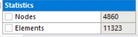
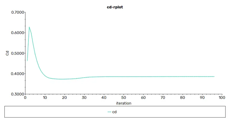
Element Size - 150 mm
Secondary volume sizing - 150 mm
Ahmed Body Sizing - 40 mm
Legs Sizing - 5 mm
Inflation layer total thickness - 12.5 mm
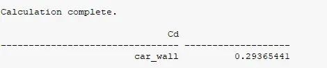
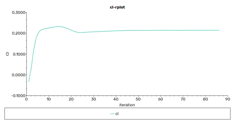
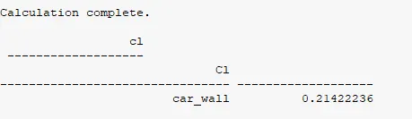
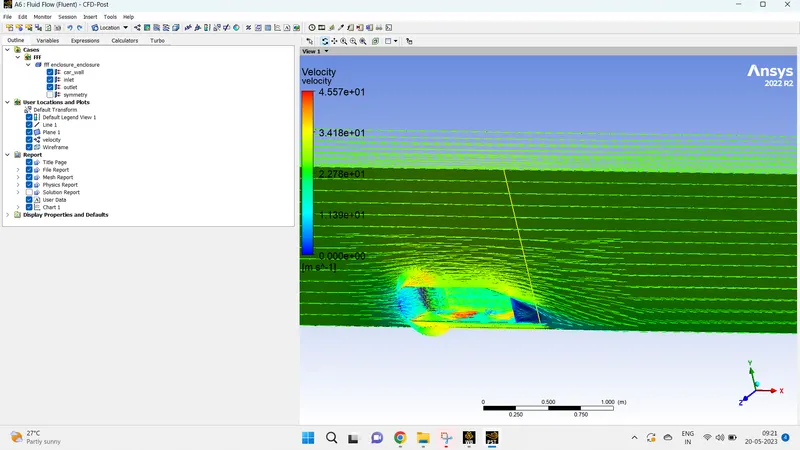
Mesh 1 Results
Element Size - 100 mm
Secondary volume sizing - 80 mm
Ahmed Body Sizing - 10 mm
Legs Sizing - 5 mm
Inflation layer total thickness - 12.5 mm

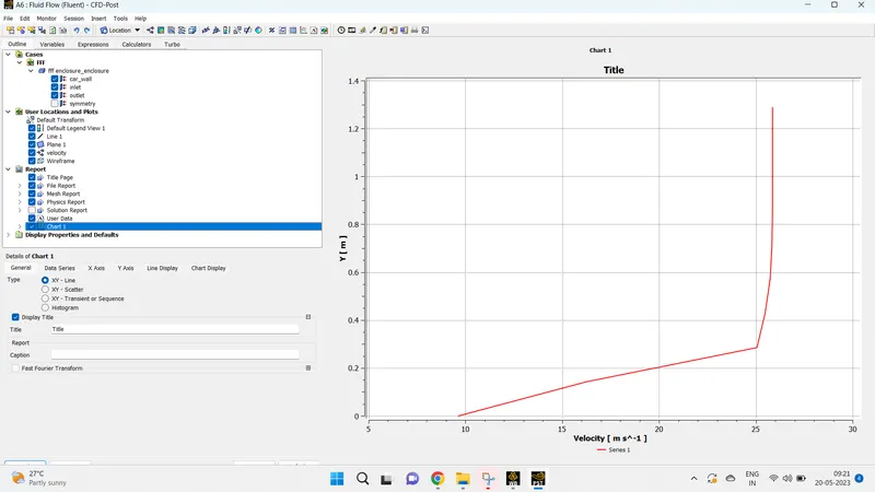
Mesh 2 Results
Element Size - 100 mm
Secondary volume sizing - 60 mm
Ahmed Body Sizing - 10 mm
Legs Sizing - 5 mm
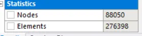
Inflation layer total thickness - 12.5 mm
Mesh 3 Results
Element Size - 100 mm
Secondary volume sizing - 30 mm
Ahmed Body Sizing - 10 mm
Legs Sizing - 5 mm
Inflation layer total thickness - 12.5 mm
Results And Conclusion
| Mesh | Nodes | Elements | Coefficient of Drag | Coefficient of Lift |
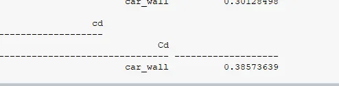
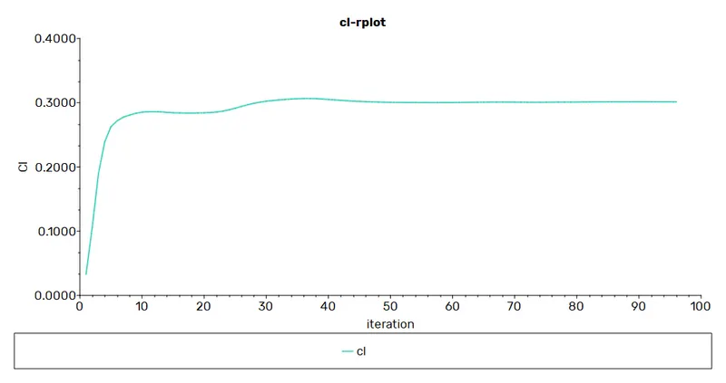
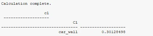
| Initial | 4860 | 11323 | 0.38573639 | .30128498 |
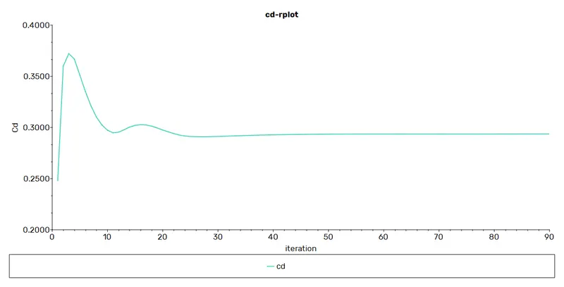
| Mesh 1 | 85851 | 263978 | .29365441 | .21422236 |
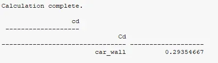
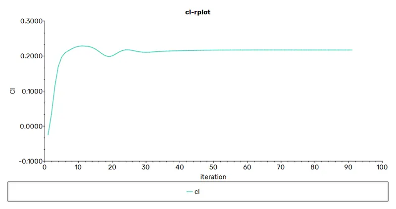
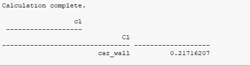
| Mesh 2 | 88050 | 276398 | .29354667 | .21716207 |
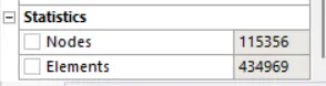
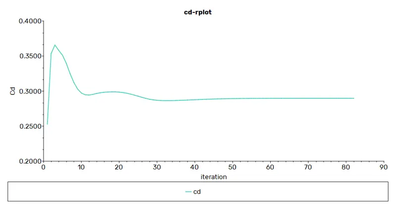
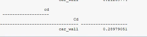
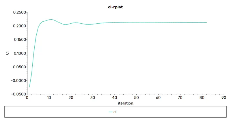
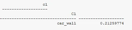
| Mesh 3 | 115356 | 434969 | .28979051 | .21259774 |
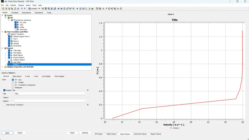
- Refinement of mesh improves the accuracy of Coefficient of lift and coefficient of drag. Aerodynamic Study of an Ahmed Body with the help of CFD Simulation by Indrashis Saha shows drag coefficient of 0.28 at 25 m/s.
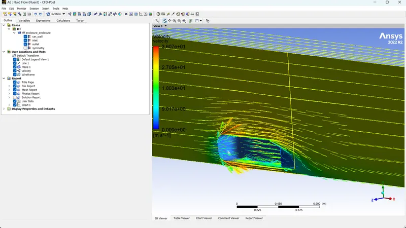
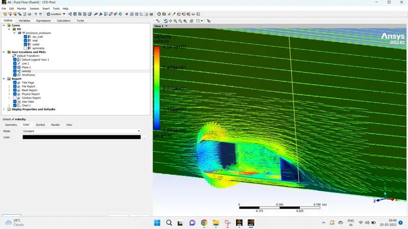
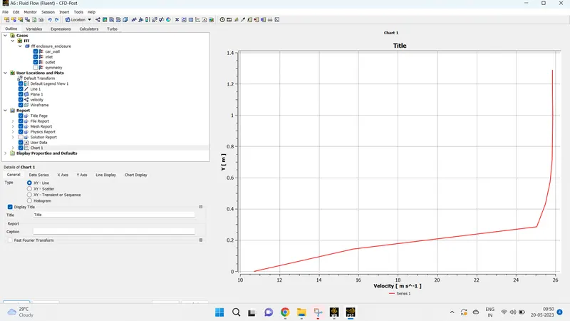
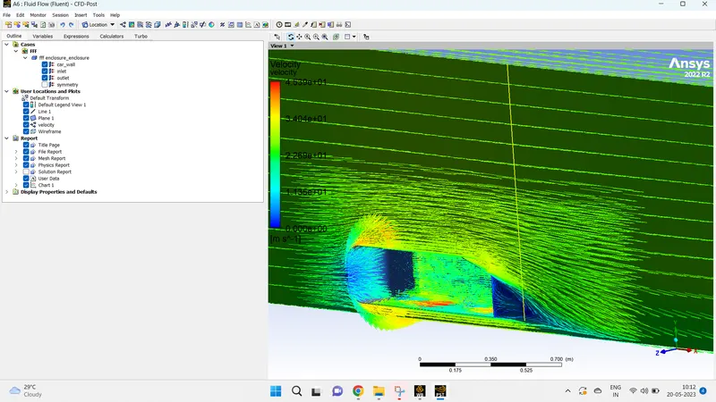
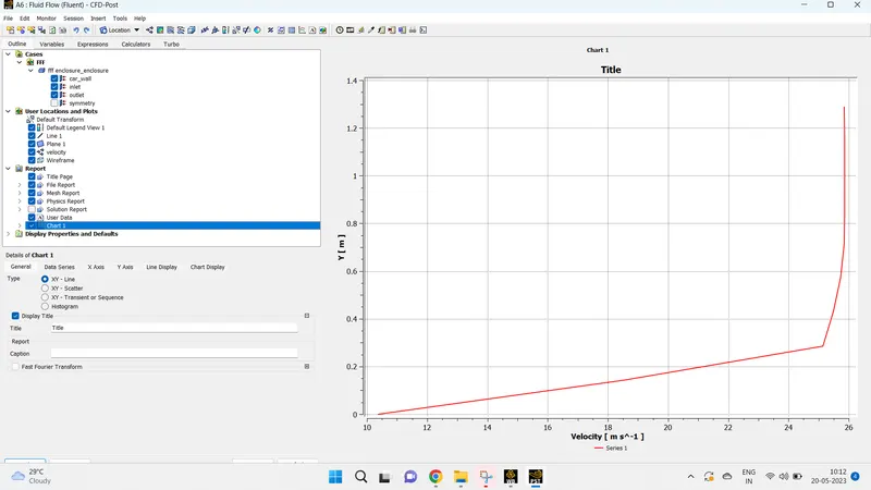
- Mesh refinement also improves the velocity vector plots at the recirculation region as shown in the above pictures.
- Optimal mesh sizing have to be selected by mesh independency study keeping in mind the computational time required to do the simulation to give acceptable results.