Week 3 - External flow simulation over an Ahmed body.
Aim : Simulat the flow of air over an ahmed body and analyze the results.
introduction : In automotive industries whenever new vehicles are designed there arises the need to analyze the effect air flow over the car design. the ahmed body is used as a reference for analyzing the results of the simulatio. The Ahmed body is a geometric shape first proposed by Ahmed and Ramm in 1984. The shape provides a model to study geometric effects on the wakes of ground vehicles (like cars). The results o fahmed body can be taken as a refernece when analyzing the result sof newly developed car. Here in the simulation we can analyze the Lift, drag wake region and velocity changes over the body of the ahmed body.
Tere are many advantageous in using ahmed body. since the desgin is simple we can analyze how the drag is generated over the body. we can use tis data to design a car in a more aerodynamic way where the drag produced in lesser.
Procedure :
- prepeare the model in space claim
- mesh the model
- nae mthe faces
- create necessary inflation elements
- use appropriate solveing mehtods to solve
- plot the required graphs
- analyze the results
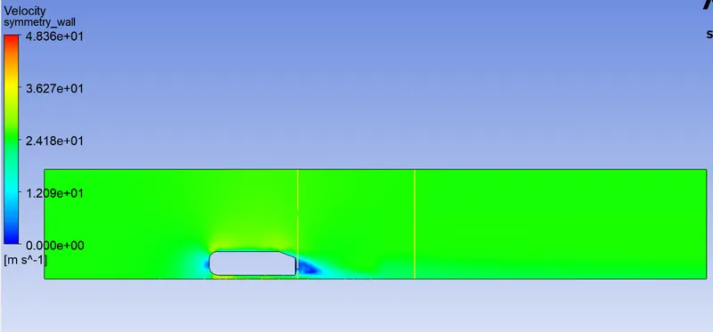
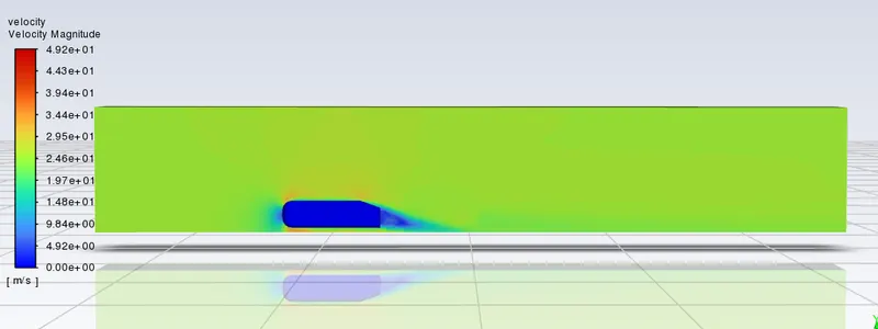
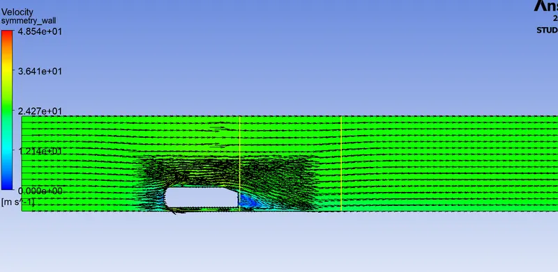
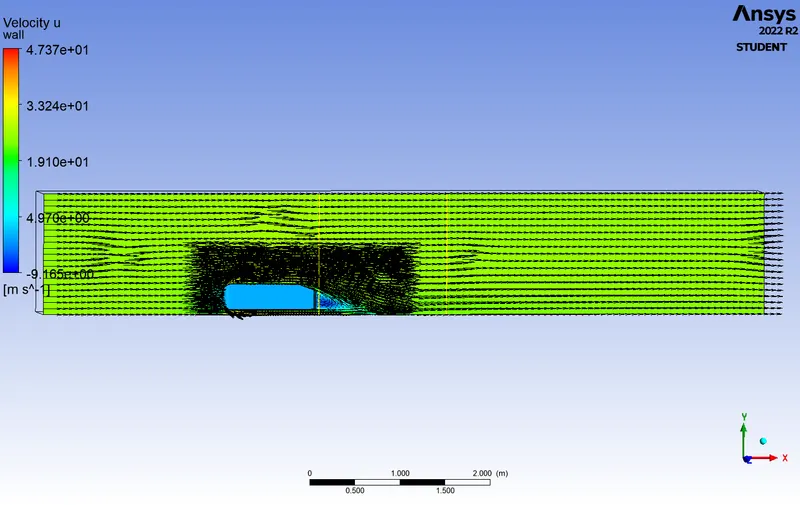
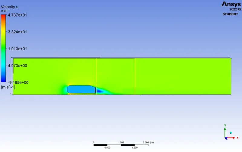
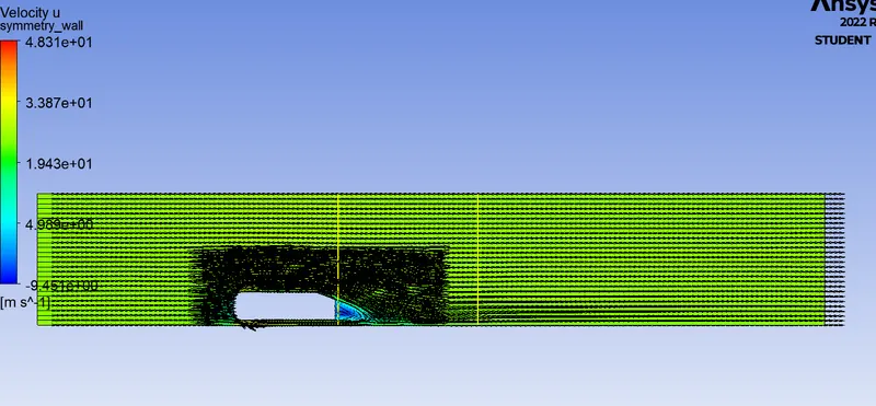
wake region, when the air moving over the vehicle is separated at the rear end, it leaves a large low-pressure turbulent region behind the vehicle known as the wake. This wake contributes to the formation of pressure drag. as teh air flows over the ahmed body, the flow starts to seperate at the nback of the body where there is a slant face. in snadstill condition the air would mix in this area but as the body is moving the air flow along the slope and creates a low pressuer space called as waske region.
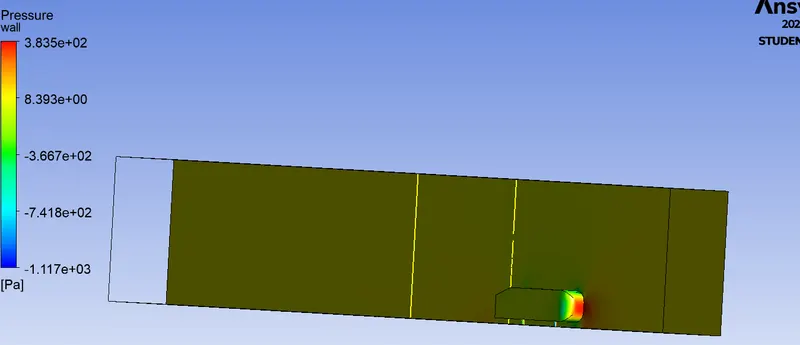
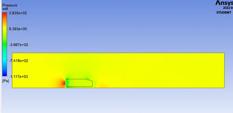
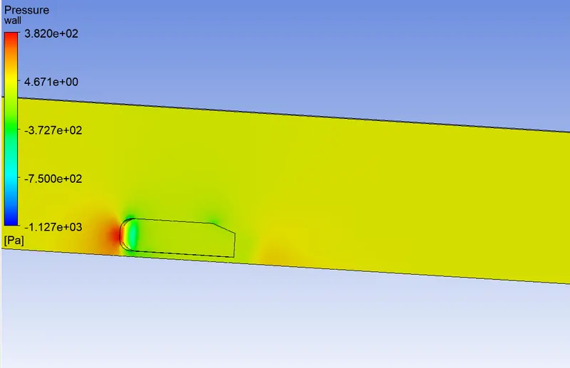
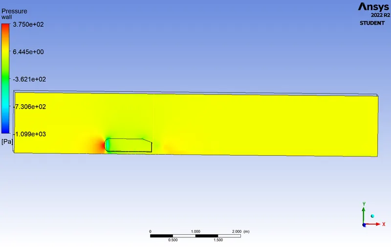
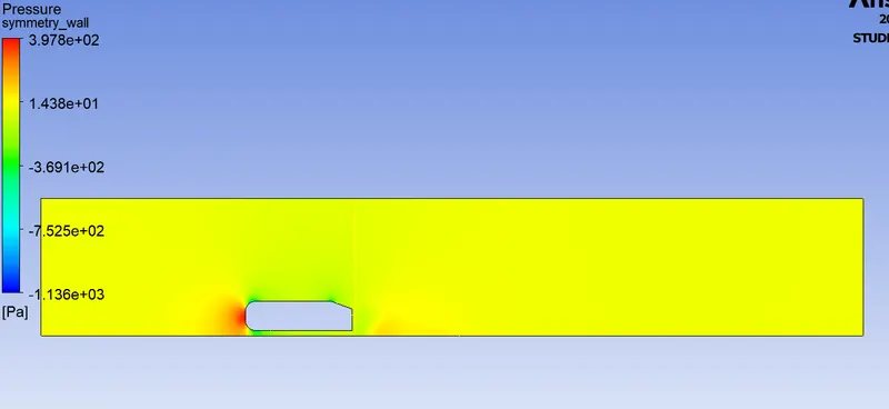
as the air is flowing along the ahmed body at thefront of the body the air flow comes to a hault and created a high pressure area. and then the air flow split along the curved face and move towards the top and bottomm of the body flowing along the body and the velocity iis also reduced. the air flow along the body, at the end of the body at the slant face the air move the same direction without mixing at the back. thus a vaccum is creates a vaccum at the back of the ahmed body. this vaccum space causes the pressure drop in the wake region.
In the case of sharp transitions or when flowing around blunt bodies, however, the fluid is often no longer able to follow the profile. The boundary layer or flow begins to detach itself from the body surface. This is referred to as a boundary layer separation or flow separation. in the ahme body the point of seperation is at the back where the top face and the slant face are joined.
Solving and modelling :
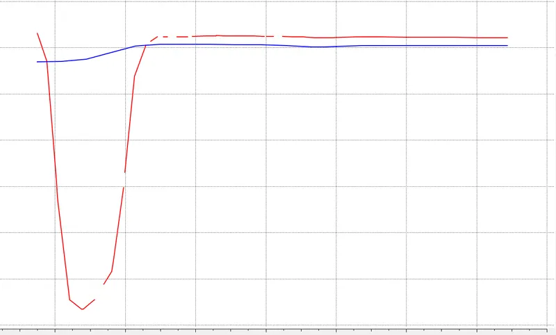
In this analysis the flow of air over ana hmed body is simulated using Ansys fluent. The analysis is done with a k-`omega` viscous model in a steady state density based solver. The simulation is oden with various size of mesh in order ot analyze the results and to run the grid independency test. For this the model is generated inn space claim and enclosures are aloso generated and defined in space calim. Then the geometry is meshed in ansys mesh. the mesh criteria and other factors related ot mesh are all defined in this stage. ater that the geometry is set up applying the required equations and solving methods in ansys fluent the velocity is set to 25 m/s. the coefficient of lift and drag plots are plotted. after that the simulation is rum for 500 iterations. ater the completion of the iteration then in ansys solution the velocity and presuure plots are created and the velcity at the wake region and at a distance from wake region are also plotted using chart.
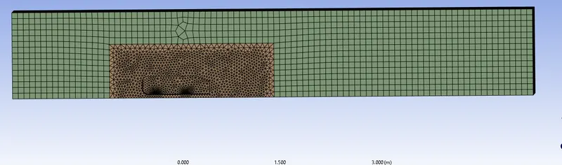
in this simulation due to the symmetry of the body the model is split in half to reduce the number of elements. in mesh the split command is used to split the entire geometry. and the unwanted parts are removed. in space claim > prepare encclosure command is used to crete the encloure and the share topology is enabled for the entire geometry so as to get proper mesh. the interface command is used to find over lapping sections and solve the issue. the ahmed body is suppresed for physics as we are conducting external flow analysis.
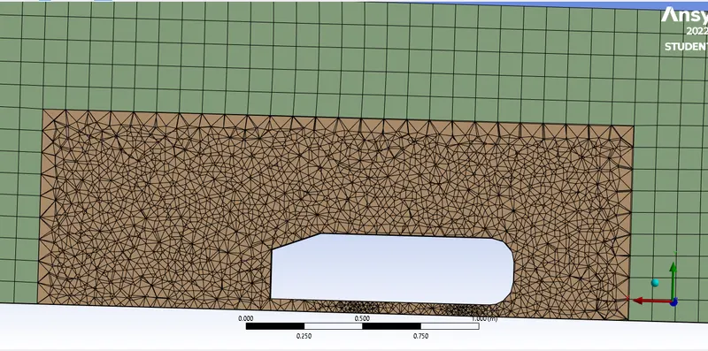
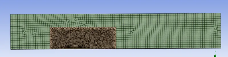
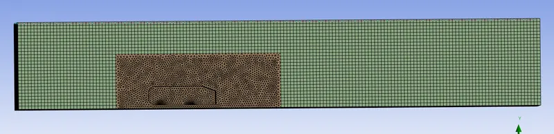
in ansys meshing the sides of the geometry are named as inlet , outlet, wall, cut symmetry and symmetry. in mesh the method, multizone method is used to mesh the entire geometry. then sizing command is used to control the size of the inner enclosure mesh elements. then inflation layers are created to get the boundary layer properties accurately.
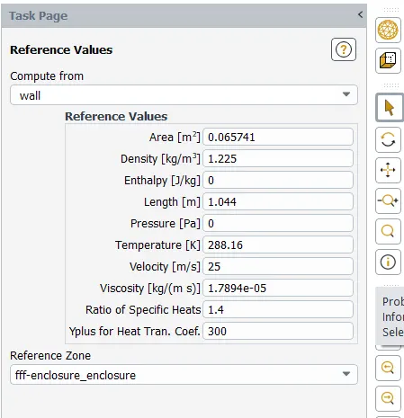
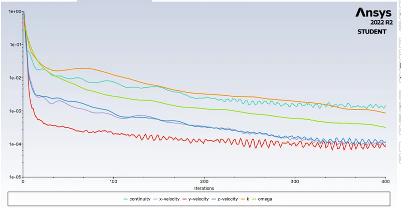
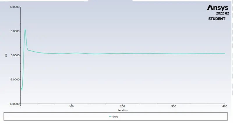
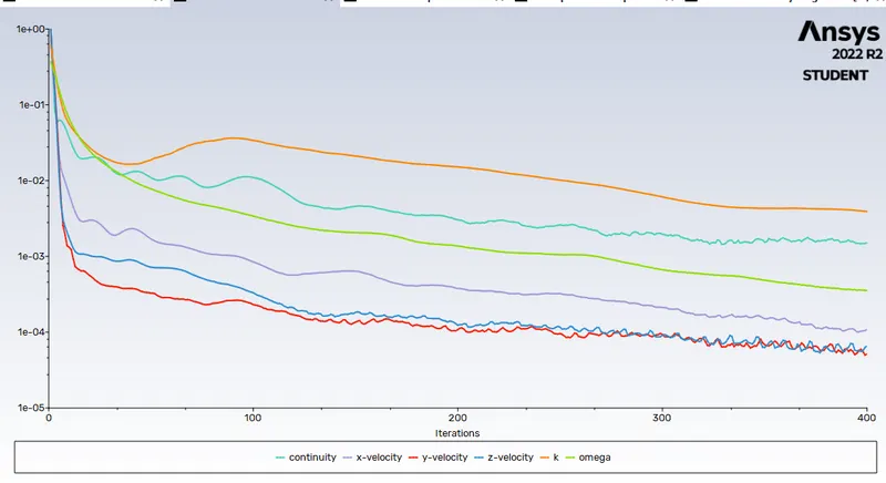
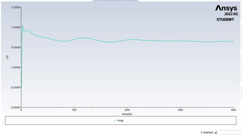
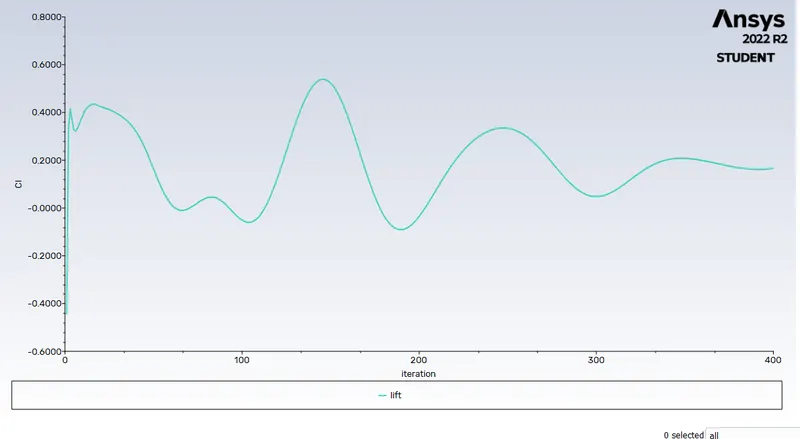
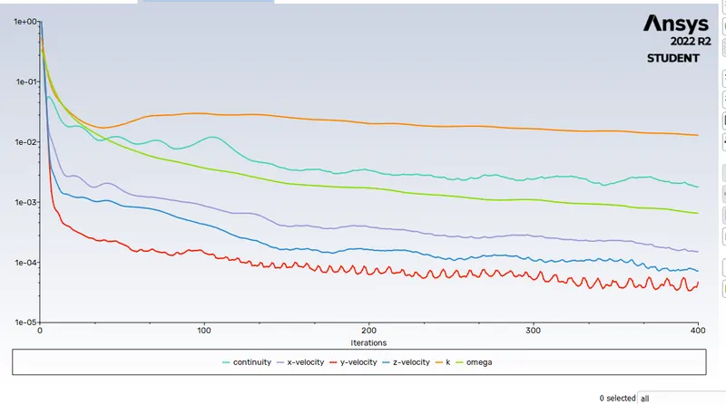
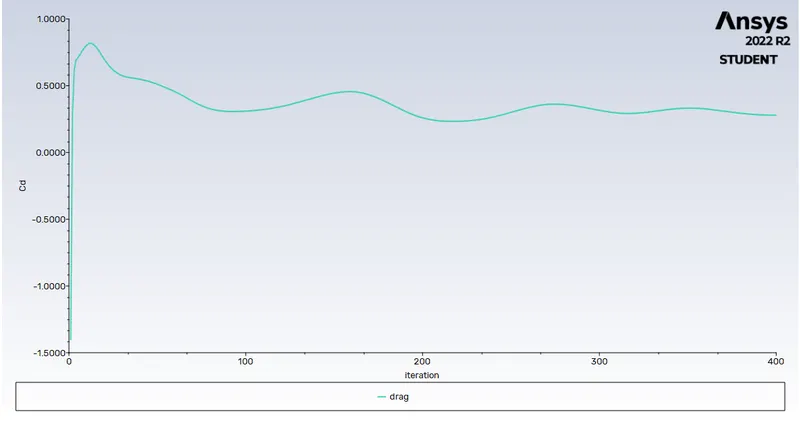
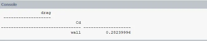
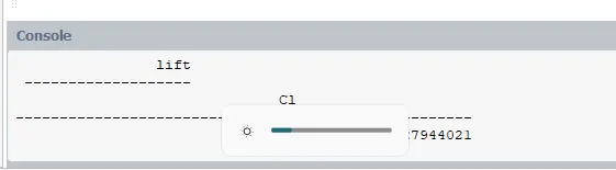
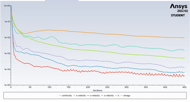
after meshing in ansys solver the conditions for the simulations are set. in physics teh solver type is set to density based and steady state flow is selected. and for viscous model the k- omega SST is used. in boundaries inlet the velocity is set to 25 m/s. in solution > definition > new > force report lift and drag along the wall is generated. the solution is then initaiated using hybrid initialisiation and then in results contours th pressure and velocity contours are also created. the area of the split ahmed body is calculated using the projected area command in reports. the area and the lenght of the ahmed body in z directiion was set in reference values. then the solution was run for an 500 iteration. and teh residuals chart is analyzed. the coeffecient of drag and lift are also computed from the report.
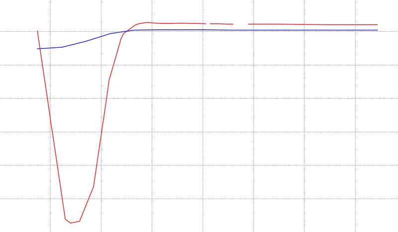
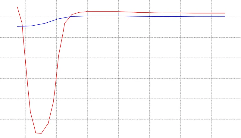
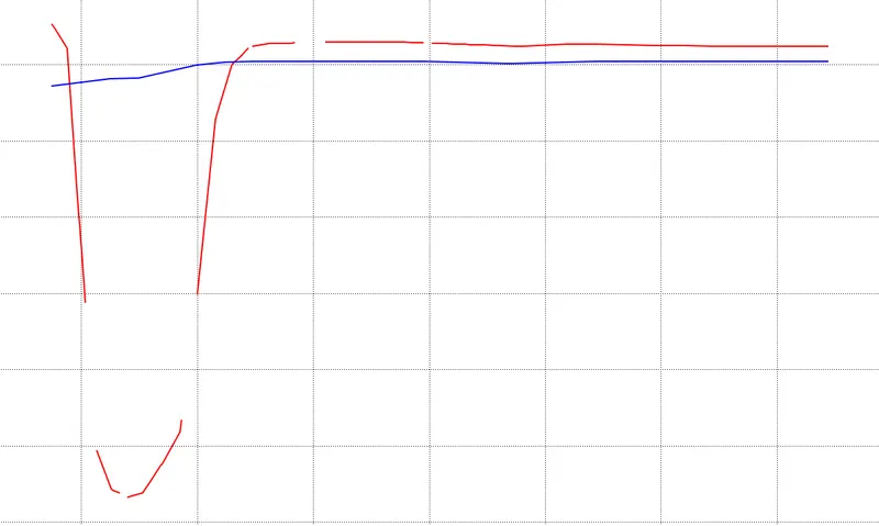
in the results the velocity and pressure are plotted along the cut symmetry. the velocity vector is alos plotted and lines are inserted at the back of the ahmed body at the wake region and at a distcance from the end of ahmed body and a velocity chart of the lines are plotted.
the whole simulation is repeated by varying the mesh element size to caluclate grid independancy
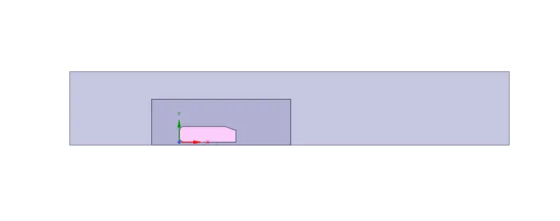
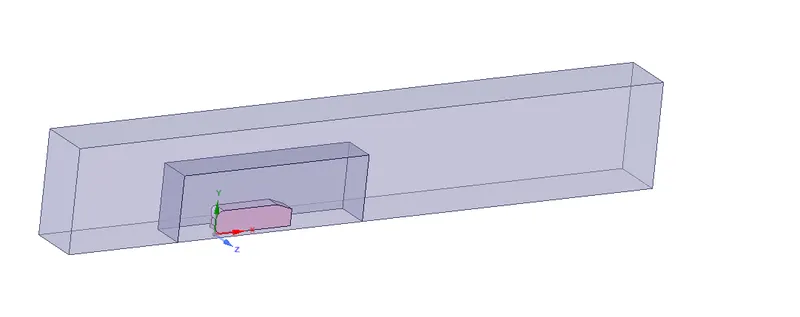
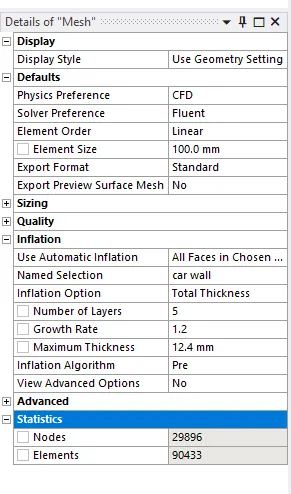
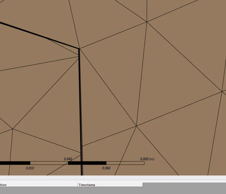
case 1
Outer enclosure mesh element size : 100mm(elemental size)
inner enclosure mesh element size : 50mm(elemental size)
Face sizing for Ahmed body : 5mm(elemental size)
inflation for ahmed body : 5layer with total thickness 1.24mm
number of total cells : 98338
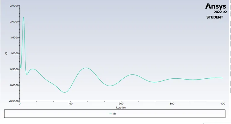
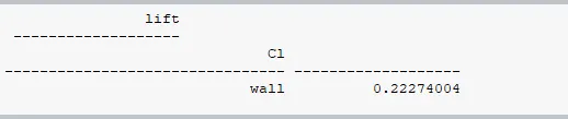
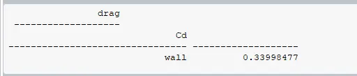
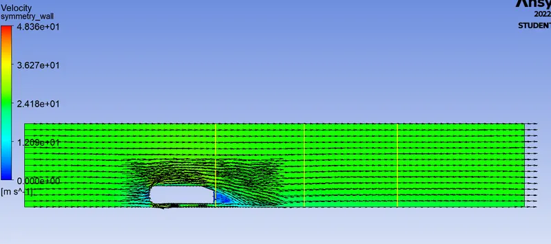
case 2
Outer enclosure mesh element size : 90mm(elemental size)
inner enclosure mesh element size : 40mm(elemental size)
Face sizing for Ahmed body : 5mm(elemental size)
inflation for ahmed body : 5layer with total thickness 1.24mm
number of total cells : 163827
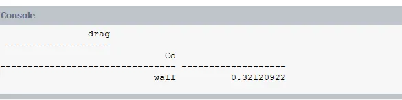

case 3
Outer enclosure mesh element size : 80mm(elemental size)
inner enclosure mesh element size : 30mm(elemental size)
Face sizing for Ahmed body : 5mm(elemental size)
inflation for ahmed body : 5layer with total thickness 1.24mm
number of total cells : 296516
case 4
Outer enclosure mesh element size : 70mm(elemental size)
inner enclosure mesh element size : 30mm(elemental size)
Face sizing for Ahmed body : 5mm(elemental size)
inflation for ahmed body : 5layer with total thickness 1.24mm
number of total cells : 371039
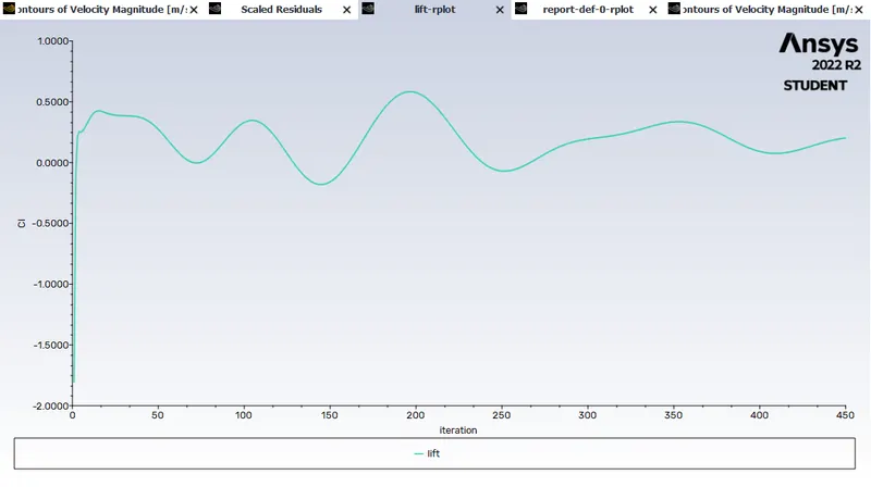
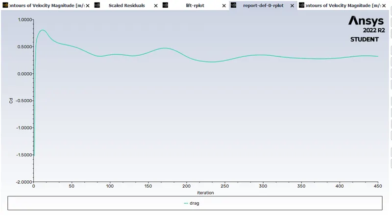
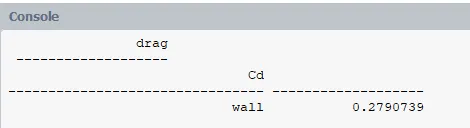
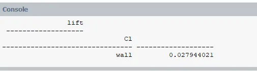
Conclusion : from the simulation and results the values at different mesh size is tabulated.
|
Result : the aimulation was conducted and the drag and lift of the ahmed body was studied. it was found that finer the mesh better the values of the drag and lift.