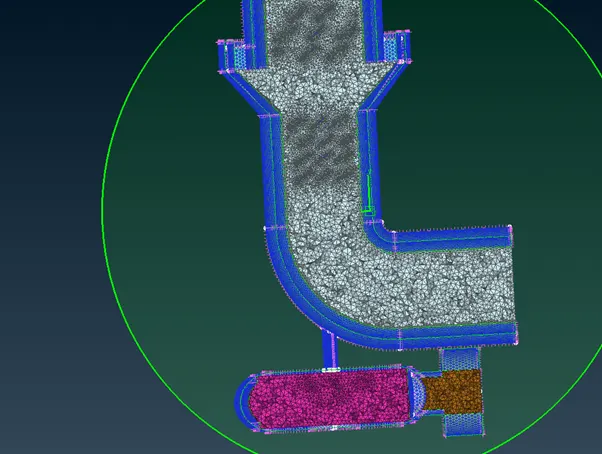
Week 3 Challenge : CFD meshing on Turbocharger
Aim :- Do a Volumetric meshing of a turbocharger.
Procedure : -
- Import the file
- Tolology cleanup
- Check for visible errors
- Check geometry and intersection errors
- Remove unwanted faces
- Prepare the model for volumetric meshing.
- Do surface meshing of each part
- Define volumetric mesh
- Perform volumetric mesh
Change view to PID
Check geometrical errors. Checks manager > geometry > execute.
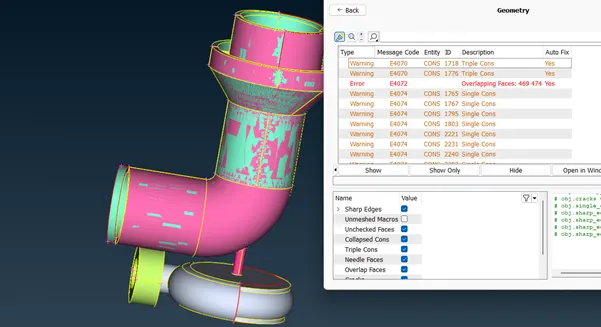
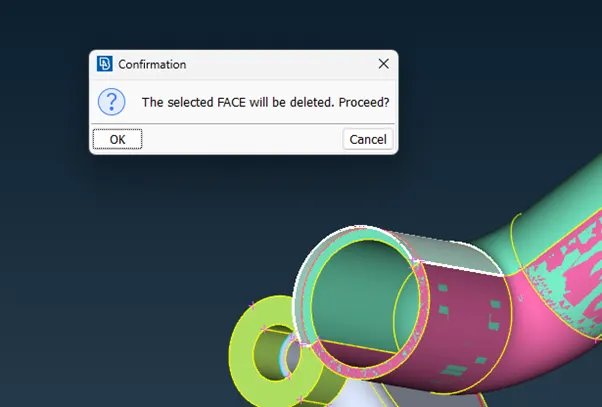
Select the overlapping surface > Delete the overlapping surface
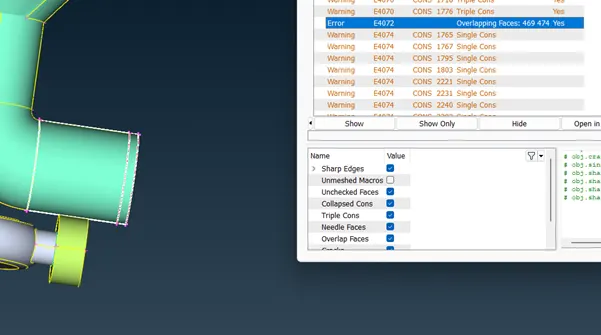
Create a new surface using Faces > coons > Loop > confirm to form correct face
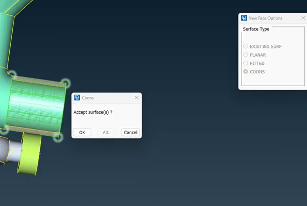
Removal of overlapping surfaces. Go to PID , select the unwanted by colour of the overlapping surface part and delete the unwanted overlapping faces.
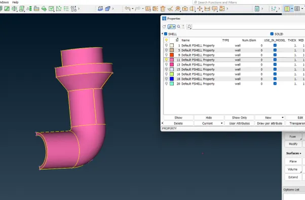
Again check for geometry check and check for single coons
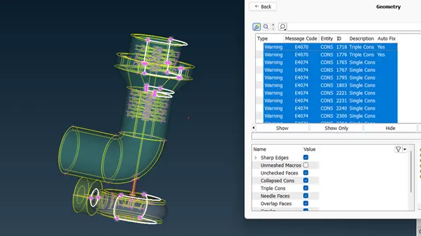
Create new surfaces to make the single coons to doble coons.
Use OR function to isolate the single coons
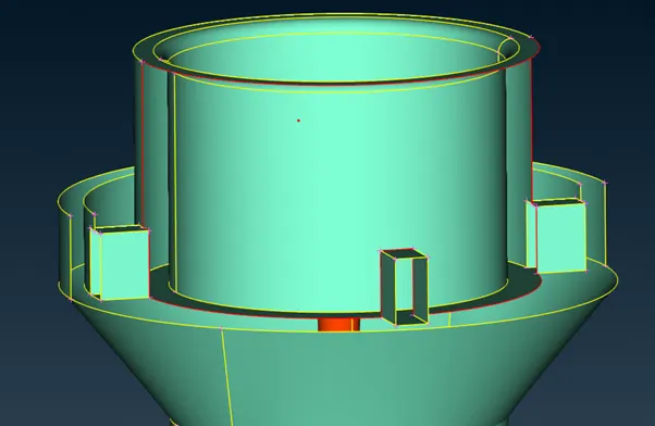
Create curves to create a new face
Curves > transform > select the curve > confirm > select nodes confirm in the direction of curves and confirm.
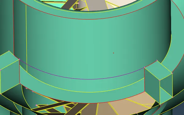
Create new face using Faces > new > entity > select entities > confirm
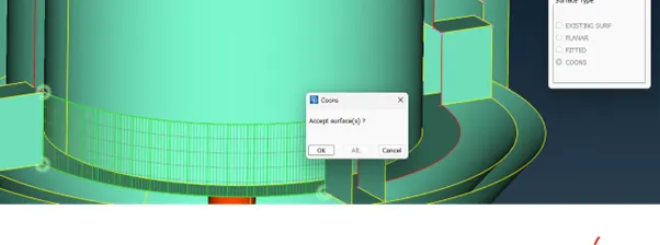
and then delete the curve after creating the new face curves > delete
to create face on the compressor casing create a hot point on the middle on the single coon
hot points > insert
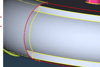
Use transform function in the top bar to create a symmetrical copy of the compressor casing on the side
Transform > copy > entities > select casing > confirm > symmetry > mirror 3 points plane > select hot points > confirm > ok > finish
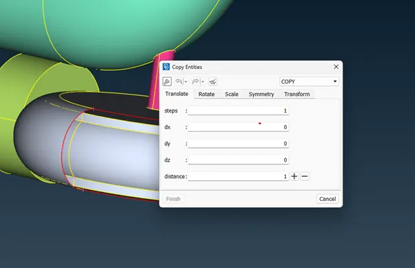
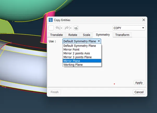
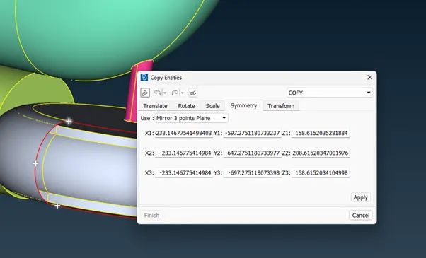
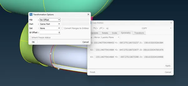
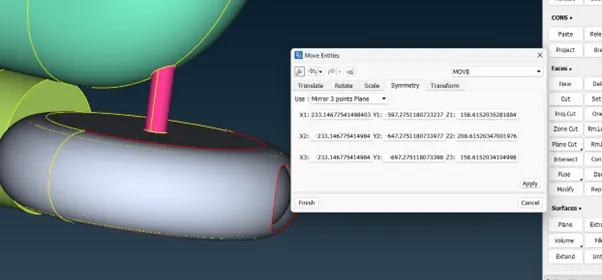
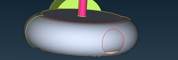
use Cons > fill hole , to fill the hole
Use Faces > Topo to correct the double cons appearing as single cons error.
Check again for penetration and intersection errors
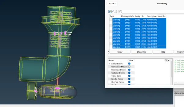
USE intersect to remove unwanted parts I the turbine casing
Faces > intersect > select firs and second faces >delete unwanted faces.
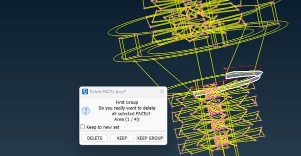
Next check for penetration and intersection errors.
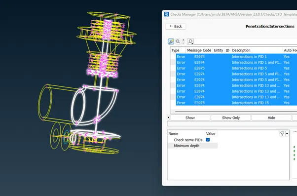
Select an error
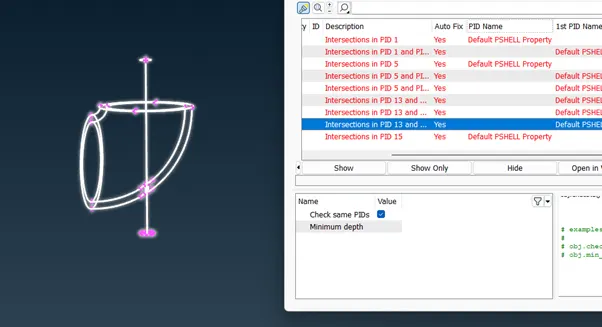
Use not function to hie faces to find the intersection error
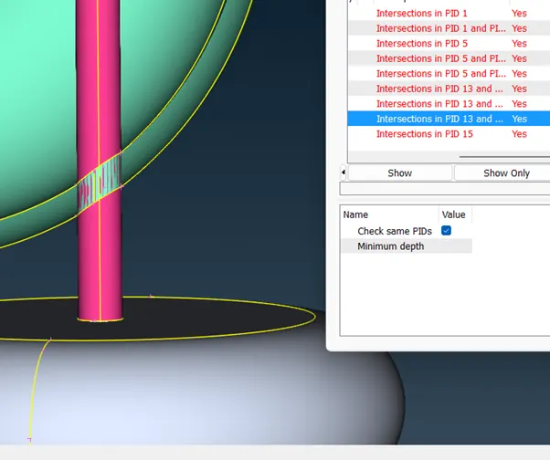
Faces > delete intersection faces.
In PID menu name each part with their respective part names
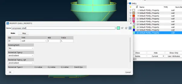
Use compress function to remove un allocated PIDs
Use Cons > project > select cons > select faces > confirm
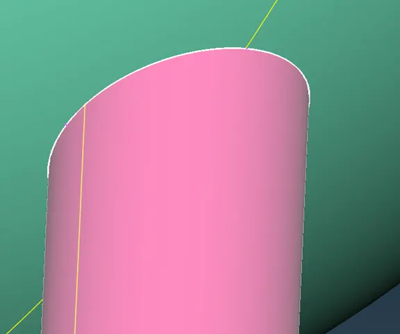
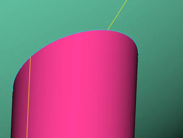
After projecting cons delete unwanted surfaces Faces > delete ( or universal delete)
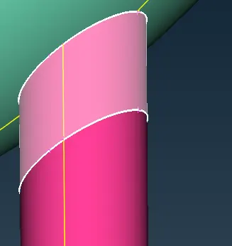
Use PID manager to display required parts
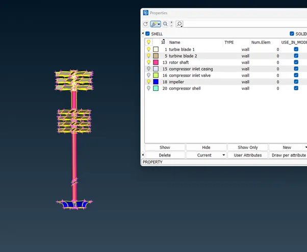
Lock screen using lock function
Check for geometry error
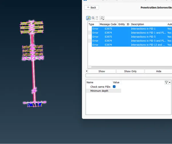
Use not function to hide unwanted face and delete intersecting and overlapping faces.
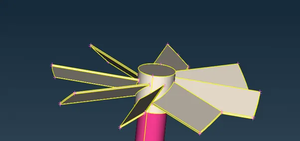
Use topo function to correct the double coons.
To solve the overlapping error on the rotor shaft and the turbine blade 2 project the cons onto the rotor shaft and then delete the overlapping surface
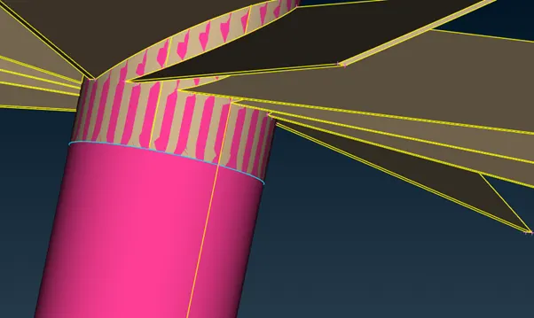
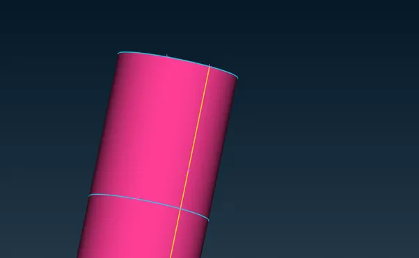
Unlock the geometry Check for geometry error
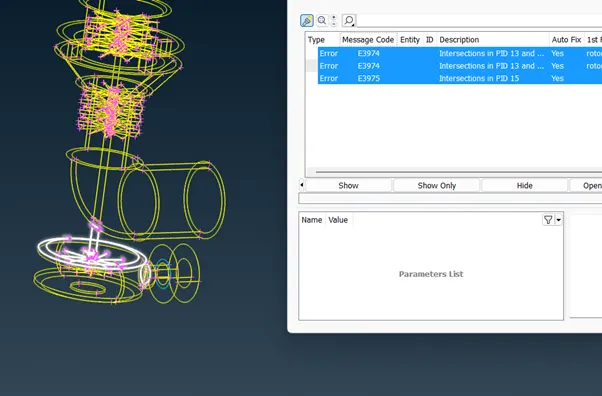
Isolate the compressor casing, impeller and the rotor shaft
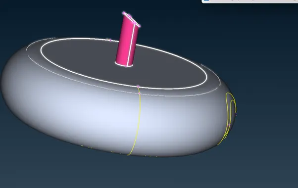
Use not function to identify the overlapping faces and delete overlapping faces
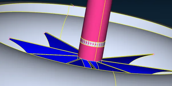
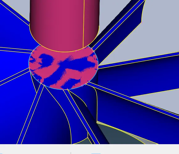
Project the rotor shaft cons onto the top of impeller then delete the impeller surface
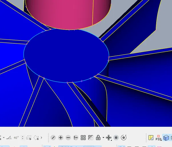
Delete the impeller surface and then undo the not function on the rotor shaft and use topo function on the impeller and rotor
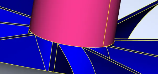
Check geometry error again
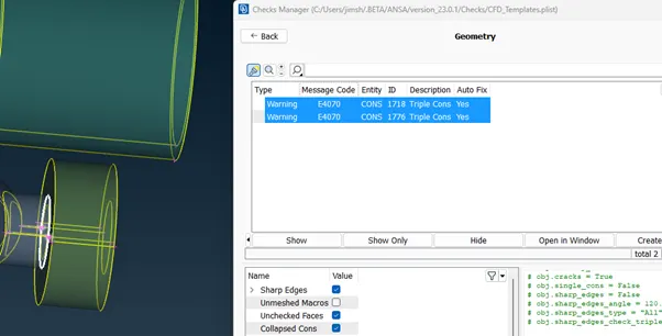
Triple cons on the surface is unavoidable proceed with the intersection-penetration checks
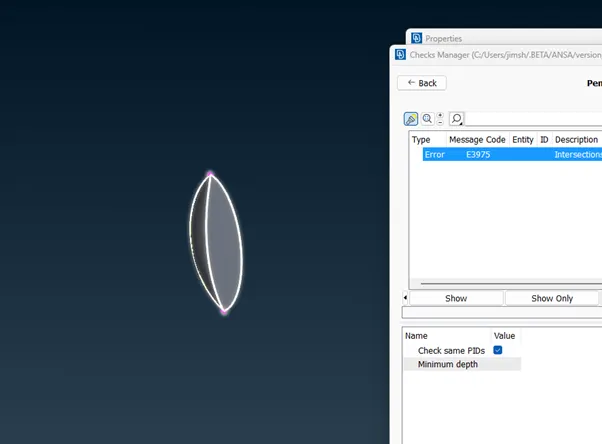
Delete the unwanted faces
Check for errors again. Then close the entire turbo charger for meshing
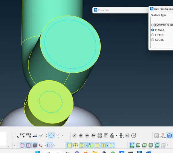
Use faces > new coons to close the inside opepening of the turbine
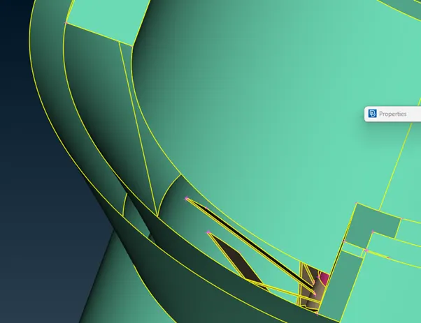
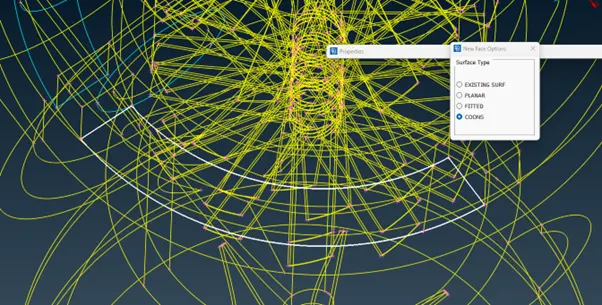
After closing all the opening start surface meshing
Mesh turbo casing compressor casing and inlet casig cover to 5mm mesh length
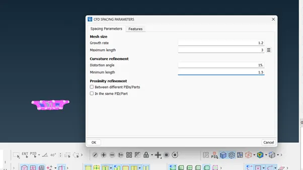
Surface mesh > Perimeters > spacing> auto cfd > perimeter > maximum length 6 mm> minimum length 4mm > macros max length 6 mm > mnimum length 4 mm
Mesh generartion > CFD> visible
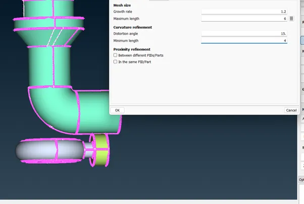
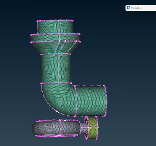
Surface mesh impeller to 2mm target length
Minimum length for perimeter 1.5 and maximum length 3
Mesh generation > CFD >visible
MACROS > freeze each PID after meshing to avoid losing surfacea mesh when varying meshes intersect.
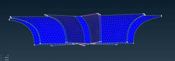
Surface mesh blade stage 1, blade stage 2 and shaft rotor having target length 1mm
Minimum length .5 an maximum length 1.5
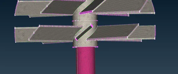
In MACROS > freeze each PID after meshing to avoid losing surfacea mesh when varying meshes intersect.
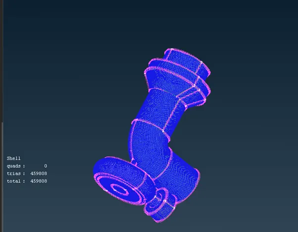
After completion of surface meshing select volume meshing
Volumes > Define > ok
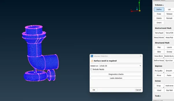
Delete the unwanted outer volume and define the internal volume
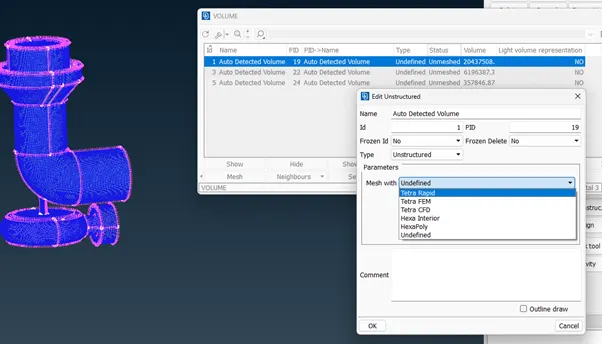
Mesh internal volume with Tetra CFD
Select the mesh to complete volumetric meshing
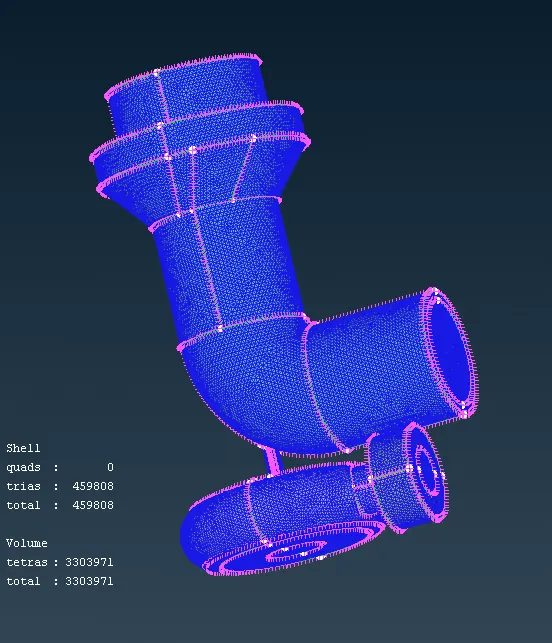
Use cut plane function to cut the meshed turbo charger I a certain plane and view the cross sectional view
Cut plane > new > default xy plane > select the point > new part