Week 3 - External flow simulation over an Ahmed body.
Aim:-External flow simulation over an Ahmed body in Ansys Fluent.
Theory:-
Ahmed's body:- The generic Ahmed Body is a reference model has been chosen as the benchmark for carrying out computations for studying of the aerodynamic parameters.The Ahmed body is a very simple bluff body which has its shape simple enough to allow for accurate flow simulation but retains some important practical features relevant to automobile bodies. It has a slant on its rear end, whose angle can be manipulated and the corresponding drag and lift coefficients calculated. This is done to exhibit the air flow over the different geometry sections of an automobile and in its vicinity, at different slantangles. This model portrays how to calculate the turbulent flow field around a simple car-like geometry using the turbulent flow, k-epsilon interface.
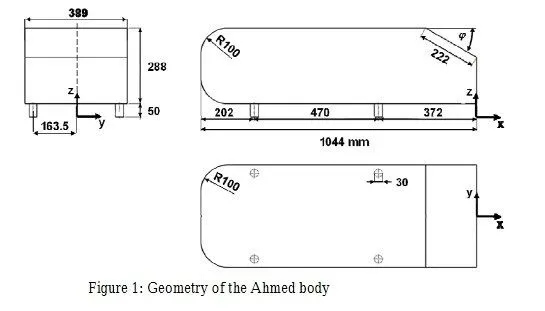
Different rear slant angles result in the emergence of different wake regions at the rear, which are mainly responsible for the drag of the vehicle.It is varying from 0 to 40 degrees.
Importance Ahmed's body
- It is an cot effective experimental tequniue to measure drag, lift, turbulence and velocity for differnt slant angle.
- Simple model for computational study requred less time and memory to capture aerodynamic characteristic relevant to bodies in the automobile industry.
- It is an simple model use to study how air tendancy of curl downward around the car's end at high speed by ploting velocity vector plot in CFD post.
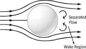
Negative pressure in the wake region
Wake region of recirculating flow immediately behind a moving or stationary blunt body, cause by viscoisty.When an bluff body comes into a flow region so at the leading end of body all fluid cover by bluf body and at that instant a void or vacume creates at traling end of body this is because of flow seperation of moving layers.
Significance of point of separation
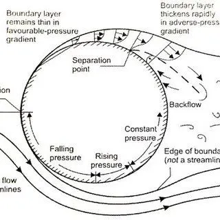
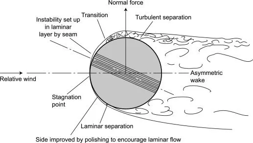
The point of separation will occur when there is a discontinuity in the surface or a region of the adverse or negative pressure gradient.When the boundary layer separates, its remnants form a shear layer and the presence of a separated flow region between the shear layer and surface modifies the outside potential flow and pressure field.
Boundary layer separation takes place whenever an abrupt change in either the magnitude or direction of the fluid velocity is too great for the fluid to keep to a solid surface.
Procdure:-
1) Preprocessing :- First import the given model of Ahmed Body in to the Ansysn Spaceclaim. Check the units in meter and mesure the length.
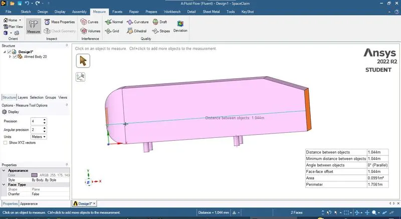
Geometrey prepair for Analysis
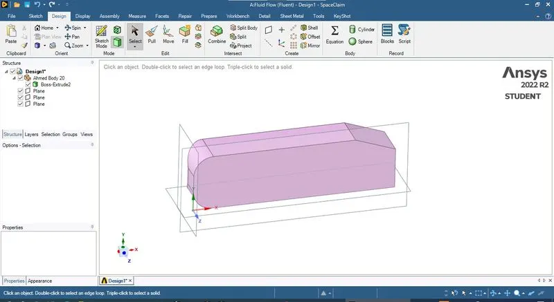
Now creates three stander mutal perpendicular palnes pasing though defult coordinate systrm of model. Now you can see our model is symetrical about plane along the length so i go to split command to spict body with respect to this plane then delete one half of model in model tree.
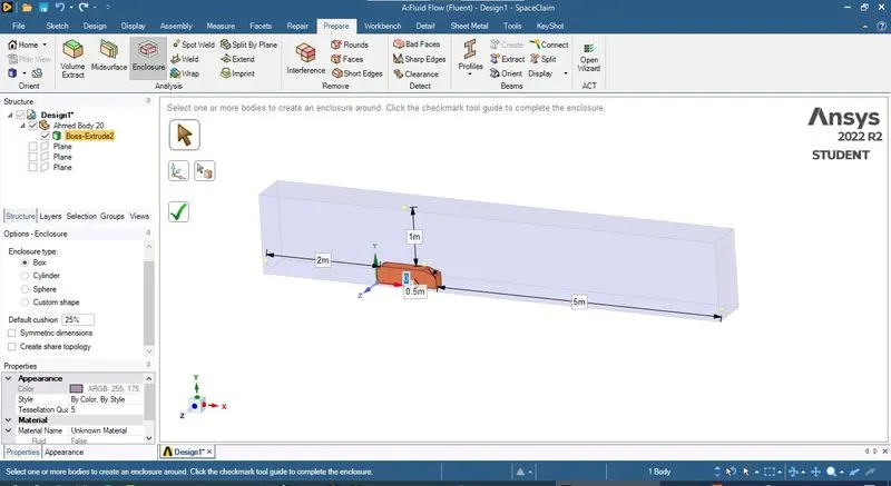
Creating Encloser
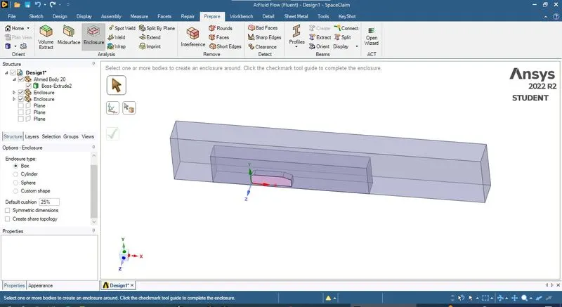
For FVM we need to create fluid volume so there we create encloser with in our body comes and fluid flows around it. Here As per wind tunnel analysis stander i creates encloser as shown in image
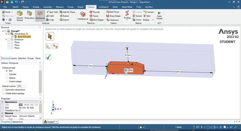
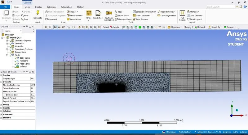
Here i have Ansys student version which allow me max 500000 elements only in meshing so for that region a creates a small encloser with fine mesh in side this lage encloser.
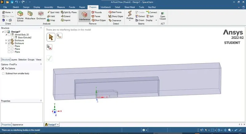
Now here my base model is interferance with encloser body so i user interfearance tool to cut this , then i supress this model for physics
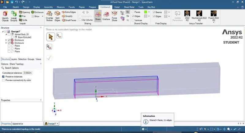
Shear data Toplogy
Now to shear Meshing data from one encloser to second
Meshing
Now close the spaceclam and double click Mesh to open Mesh enviroment
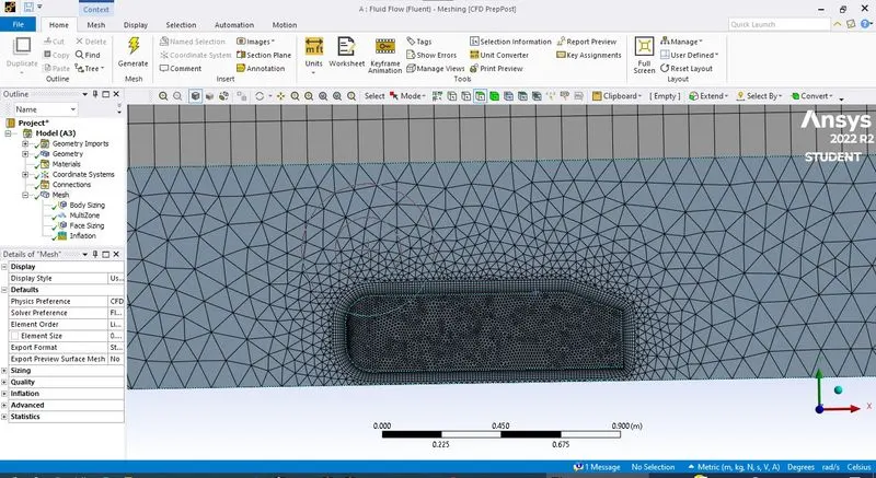
In the project tree right click Mesh > insert > sizing now enable body selecton filter and click second encloser. Now we cand give second encloser as different element size.
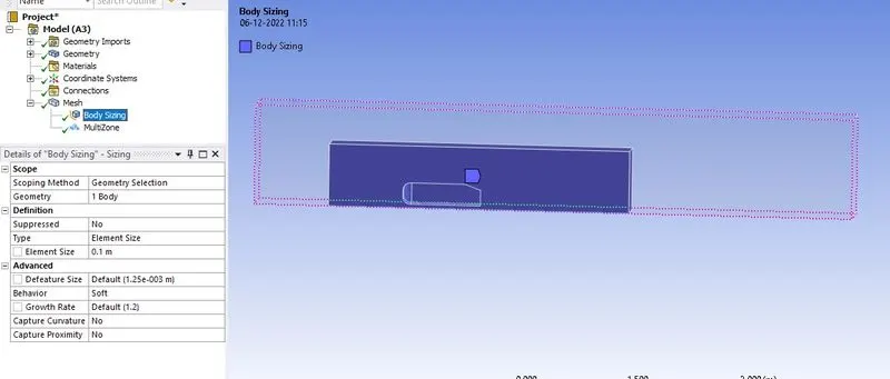
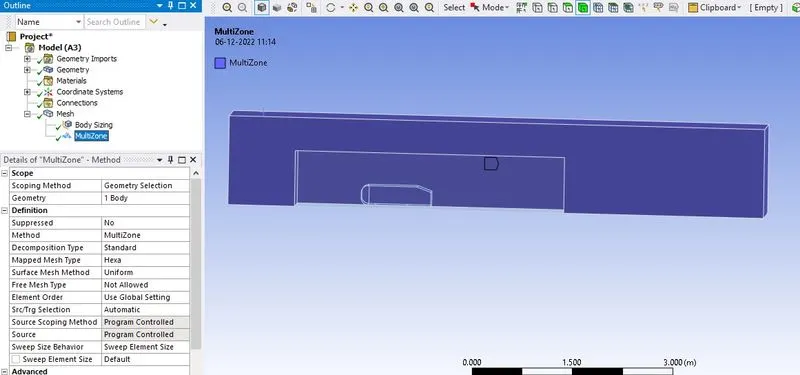
Now here i am interested to change element type for biger encolser so in project tree right click Mesh > insert > MultiZone and click first encloser and here i select hex mesh in element type.
Inflation
Now here due to viscosity of fluid boundary layer is genrated at fluid soild interface to capture effect of these boundary layer in simulation i have to creates thin element layers at solid boundary. These element layer call infaltion and total thickness of these inflation layer is higher then bounadry layer thickness.
`delta=5L /sqrt(Re)` for Laminar flow and
`delta=0.37L/(Re)^(1/5)`
To add inflation layer first right click Mesh>insert>inflation Select the model faces and choose flast layer in method
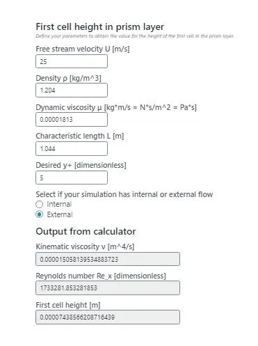
Y+ value :- Y+ is dimentionless number which is user to calculates. here i am using online first layer thickenss calculator
For K-omega model Y+ value is 1 to 5 and for k-epslin model it is 30 to 300.
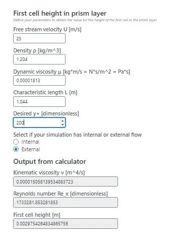
here i use 200 Y+ value and get the first layer hickness 3mm=0.003m
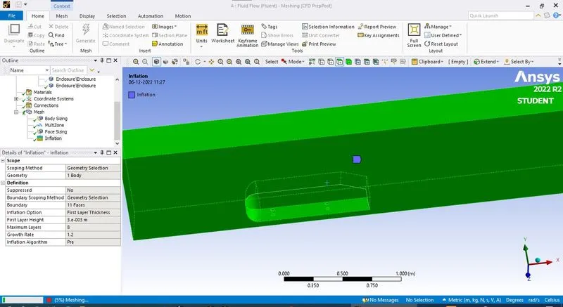
Now for smooth geomtry of model i use face sizing at inter face.
Naming Boundaries
#Grid Independece test
Here i have three case of meshing
| cases | Big encloser | small encloser | face sizing | Number of element |
| case 1 | 250 | 100 | 10 | 221516 |
| case 2 | 150 | 70 | 8 | 418325 |
| case 3 | 100 | 50 | 8 | 429839 |
2) Solver
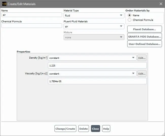
Now open the setup first give air as material
Assining boundary condition
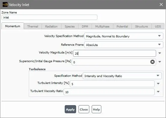
Inlet velocity
Referance value
First calculate project area
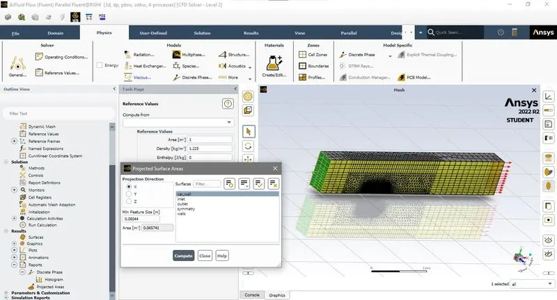
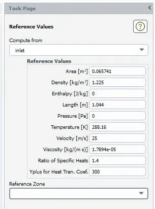
Analyis setup
Now go to the physis for analysis setup
here i choose Density base solver instade of pressure base because i have to accounts comprssiblity effects. and chosse kepsilion model.
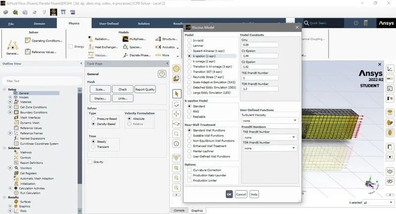
Now run the analysis.
#Residual plots :- here as always number of iteration increase with number of element.
Case 1
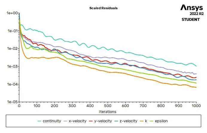
Case 2
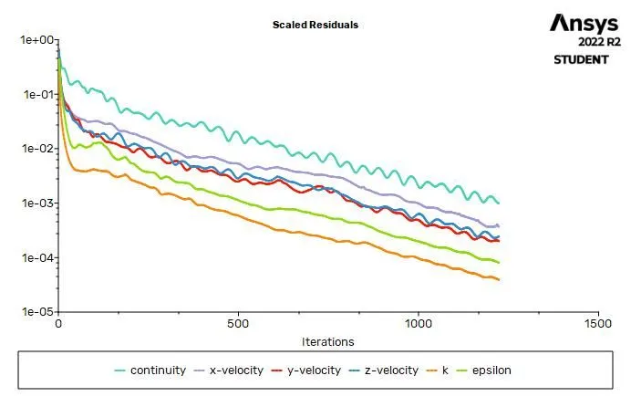
Case 3
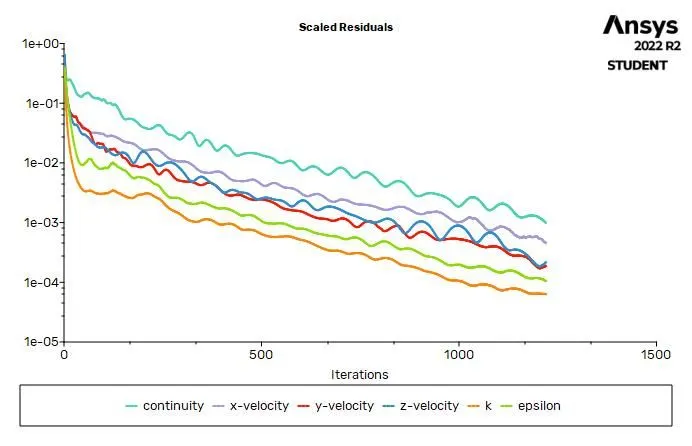
3) Post Processing
A) Velocity and Pressure contoures for refine case
Open CFD post by right clict Result. Now check symmetry and click Contour on toolbar ,Name the pressure contour and select pressure as varible.
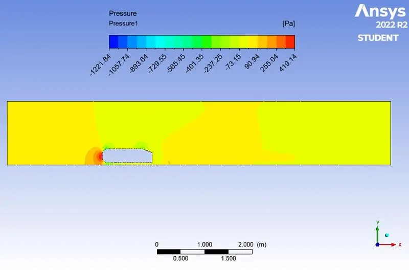
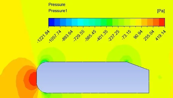
As well you can see Pressure at front end is high because as moving fluid collieds with front surface it kinetic energry convert to static energy so that its static pressure is incresses.
Now here you can see region of -ve pressure and ends of curved surface because there is flow seperation which creastes wake regions, here at sharp edge you can also see -ve pressure region because at sharp edge swriling or twisting of air occures which cause turbulance and seperation.
The "pressure" displayed in ANSYS is actually gauge pressure, the gauge pressure is 0 when the total pressure is the atmospheric pressure. In this case, the "pressure" being negative is merely the pressure dropping below atmospheric in some regions.
Velocity contours
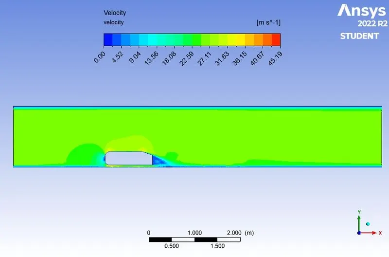
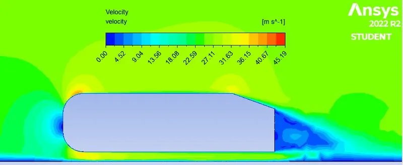
Now here you can see zerro velocity at leadding and tralling end both, At leading edge is is because sudden brakes in flow but at end it is because of -ve pressure inwake region.
B) Drag coeffcent for refine case
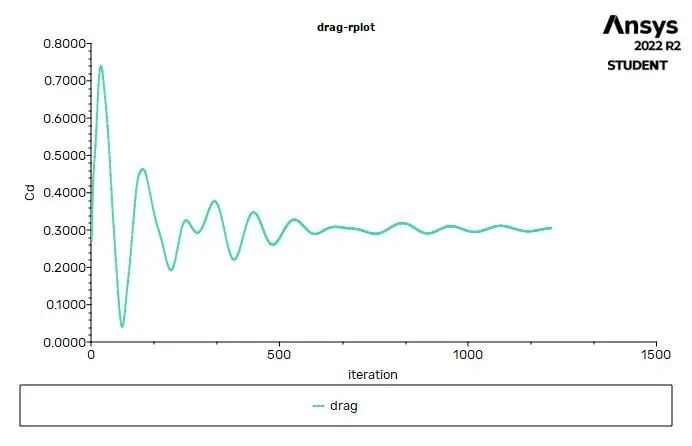
It comes raound 0.3099066
errorn inresult
(0.33-0.3099066 )*100/0.33=6.08%
C) Velocity vector plot
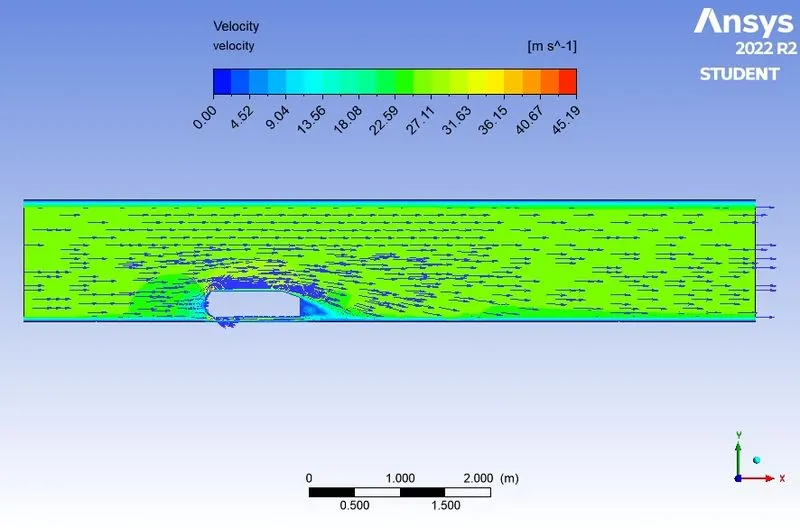
Veocity vector without contour
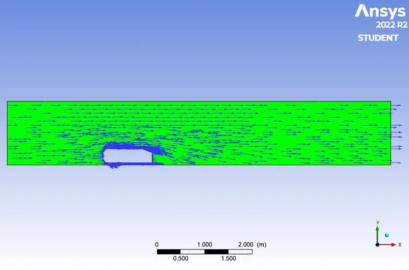
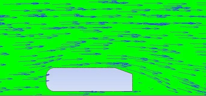
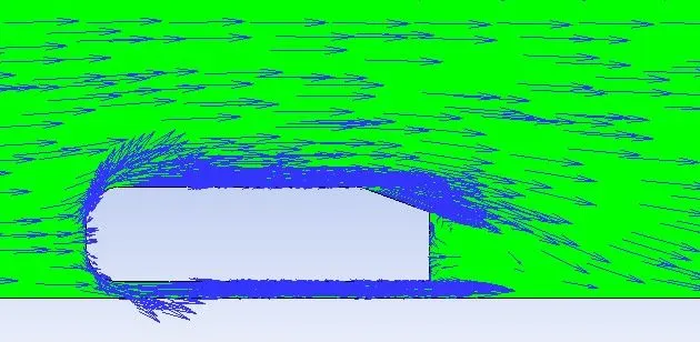
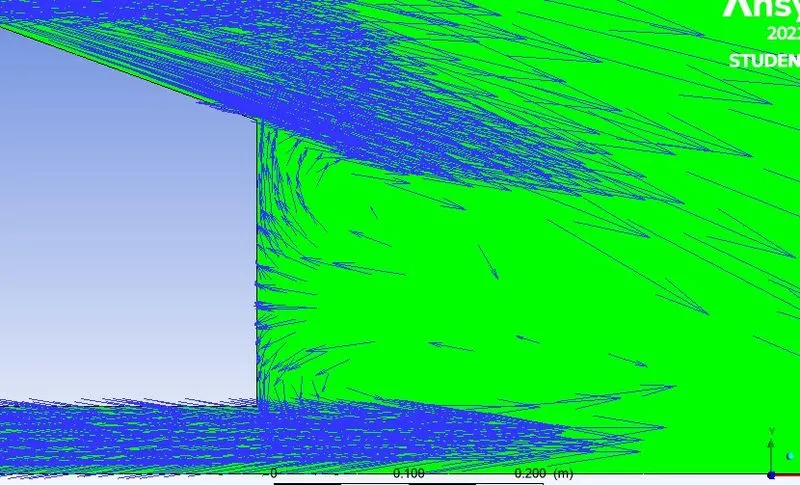
Now at Tralling edge you can see velocit vector in opposite direction becouse of adverse presure gradient in the wake region.
4) Grid independency test result
| cases | Elements | Drag | Lift | Iterations | errors |
|
Case 1 |
221516 | 0.3293471 | 0.29119135 | 1000 | 0.19% |
|
case 2 |
418325 | 0.3088150 | 0.32545765 | 1200 | 6.42% |
|
case 3 |
429839 | 0.3099066 | 0.34099316 | 1200 | 6.08% |
Here from the above grid independent test error is more in fine mesh model so for futher case studey for diffent physiscs we do not need refine mesh because coarse mesh is suffcent for giving result wirh more accurecy and consuming less number of iteration and simulation time.
Conclusion:-
- The flow around the Ahmed body is a well-known benchmark for CFD solvers with help of this we compare our simulation result with standrard Ahmed body windtunnel test for different slant angle.
- Negative pressure at wake region beacure of this oppsite velocity vector. The boundary separation and recirculating of the flow and also the effect of shear stress. To overcome this stress, the pressure turns negative for the balancing effect.
- Here mesh indepentent test is conduct for checking effect of refinment in result, there is no need to refine mesh if it gives more accurates result at coarse mesh.
Refrences