Week 3 - External flow simulation over an Ahmed body.
Aim
To describe Ahmed's body and its importance.
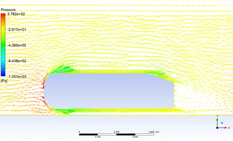
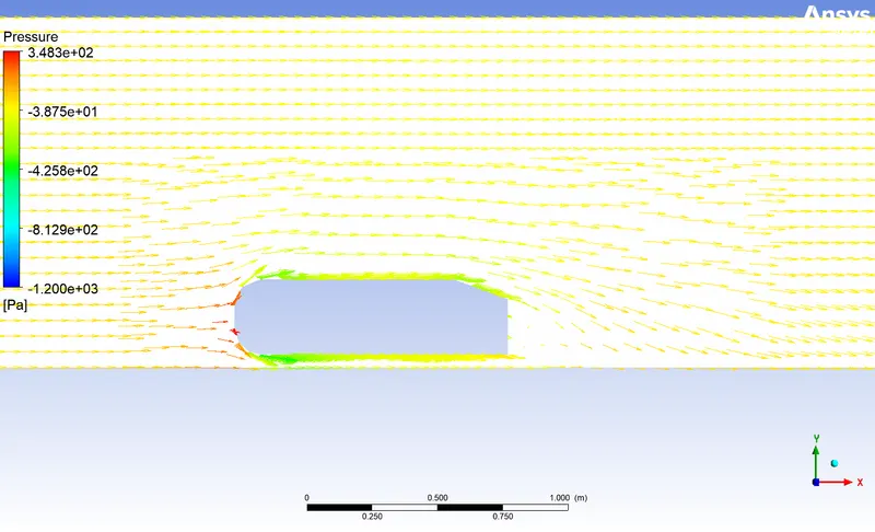
To know the reason for the negative pressure in the wake region.
The significance of the point of separation.
External Flow Simulation Over an Ahmed Body :
1. Velocity and pressure contours.
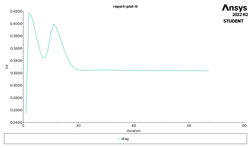
2. The drag coefficient plot for a refined case.
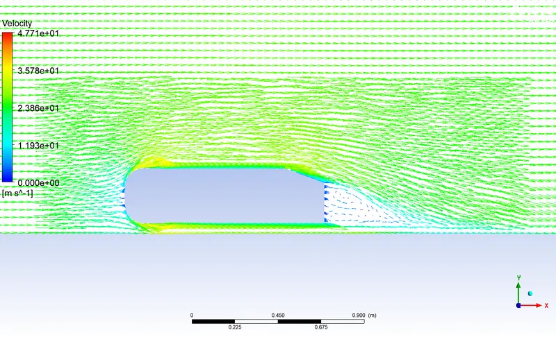
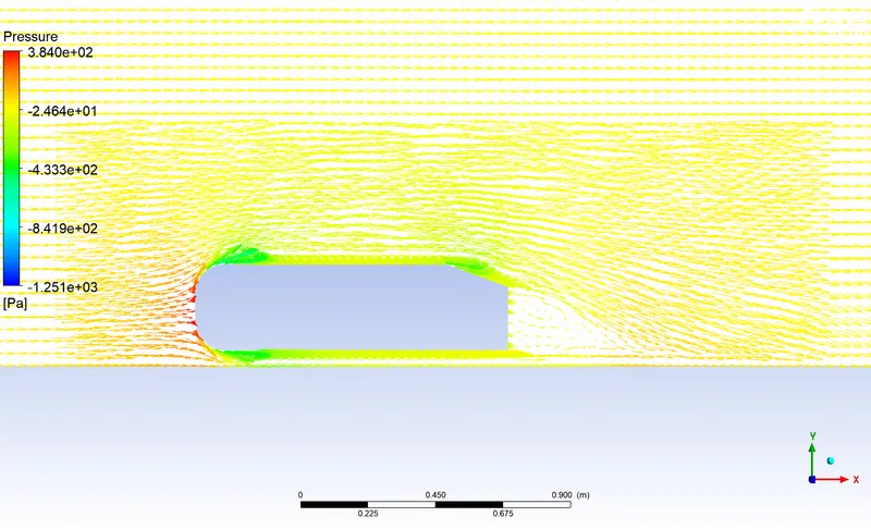
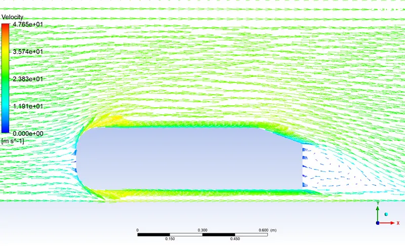
3. The vector plot clearly showing the wake region.
4. Perform the grid independency test and provide the values of drag and lift with each case.
Introduction & Theory
Q1. Ahmed's body and its importance
Ahmed's body its shape looks like a automative vehicle its importance is to study the lift, drag, weak regions around the body when it is moving through a fluid air.
Q2. Reason for the negative pressure in the wake region
Due to the flow separation the wake region is formed which causes negative pressure.
Q3. Significance of point of separation
Point of separation is the location at which the flow separates and the size of the separation determines the drag force.
Modelling Approach
The work flow for simulating flow over a cylinder :
- Pre-processing
- Solving
- Post-processing
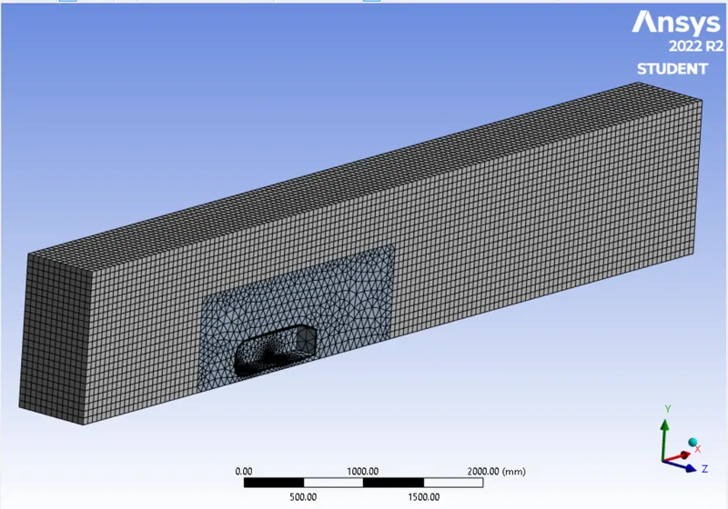
In pre-processing modelling of the geometry as well as meshing is done.
The pressure based and steady state solver is used.
For the turbulence model K Omega SST is used. Material of the fluid is Air.
To run a simulaton for the inlet boundary conditions the velocity of 25 m/s with the default air properties is choosen.
For outlet it is pressure outlet and wall boundary conditons is set for car walls. Further side faces of the enclosure is set as symmetry boundary conditions.
Geometry
The geometry is imported into the Ansys workbench using Spaceclaim option.
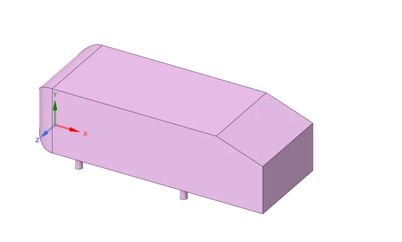
As the geometry is symmetric, we can run the simulation by considering the only half body. To get the results faster and to reduce the number of cell counts it is the best practice.
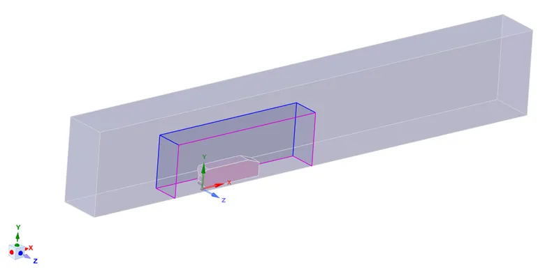
Split Body command is used to split the geometry into half portion.

After which the enclosure is created as an fluid domain.
Interference command is used to clear the overlapping areas.
Share topology is enabled to share its neighbouring faces.
Mesh
To perform grid independence test mesh with a three cases is studied.
Case : 1
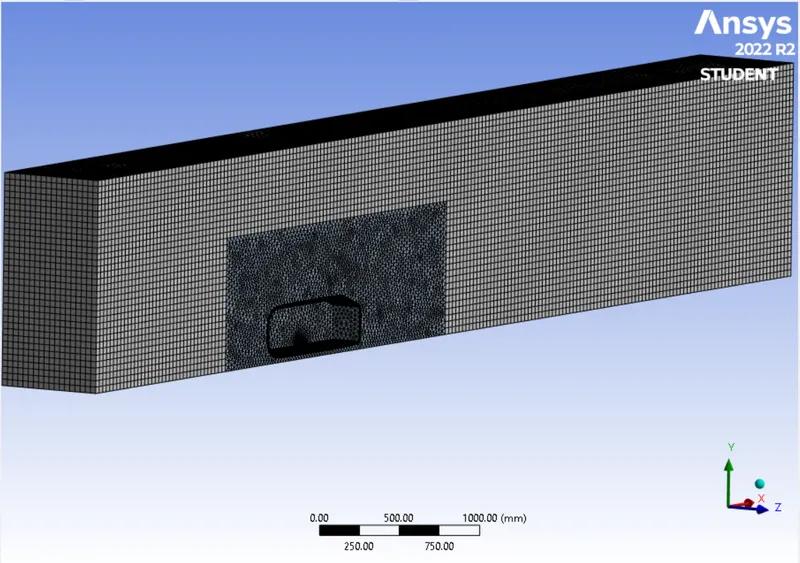
Case : 2
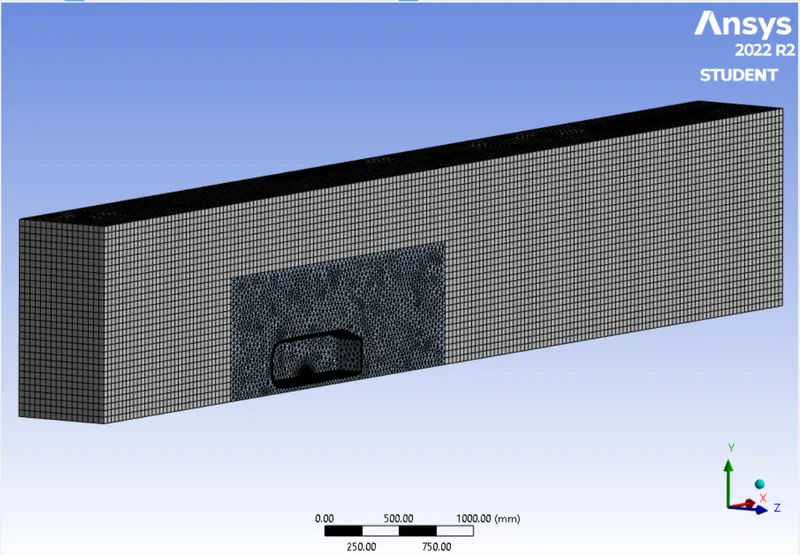
Case : 3
Results
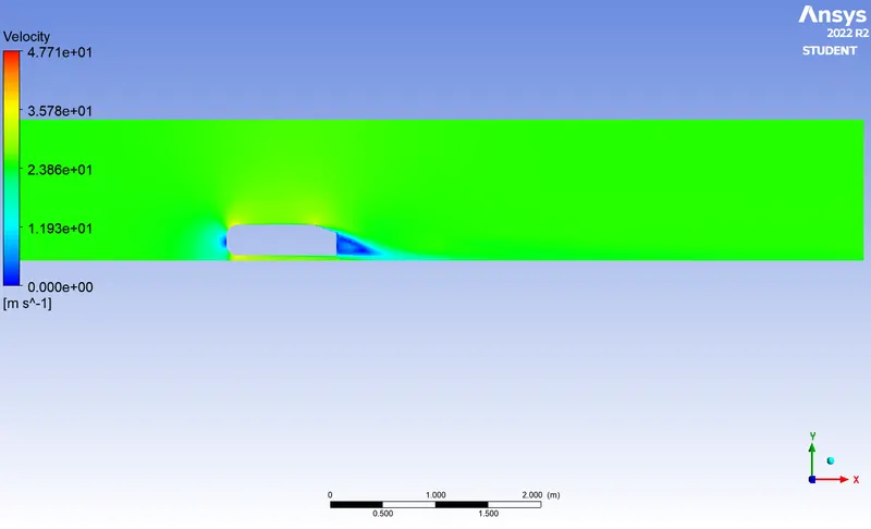
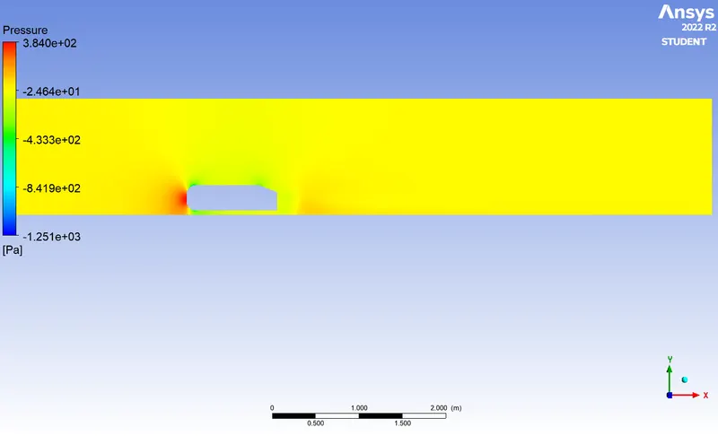
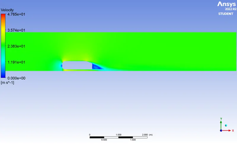
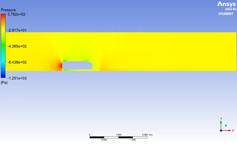
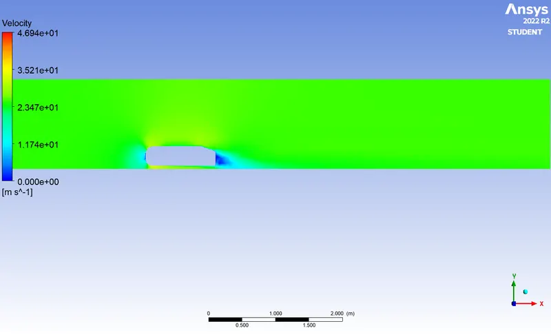
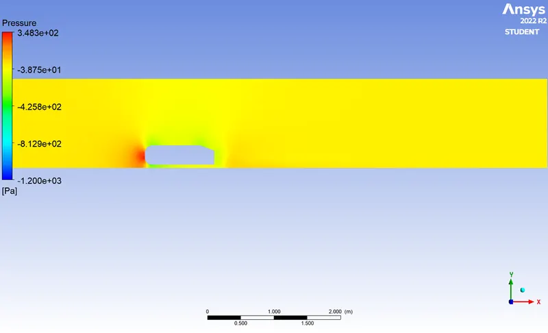
Velocity and pressure contours
Case : 1
Velocity Contour
Pressure Contour
Case : 2
Velocity Contour
Pressure Contour
Case : 3
Velocity Contour
Pressure Contour
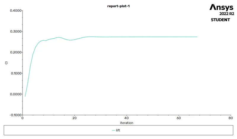
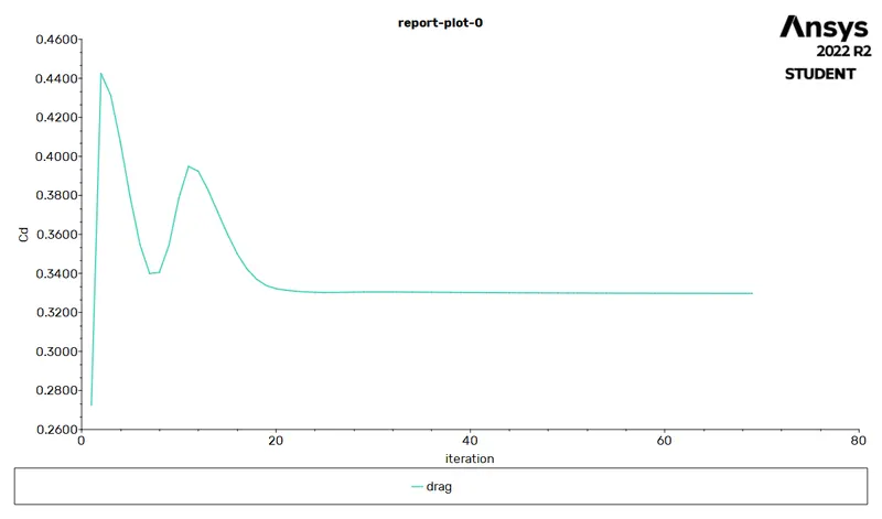
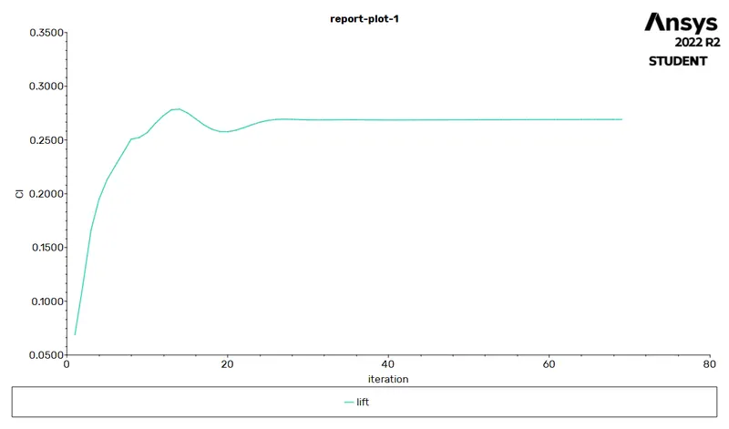
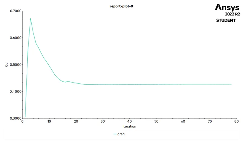
Drag & Lift Co-efficients
Case : 1
Drag Co-efficient
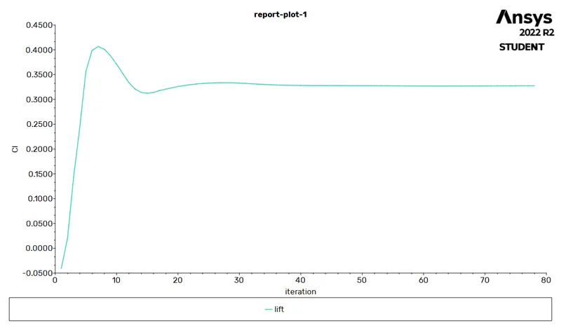
Lift Co-efficient
Case : 2
Drag Co-efficient
Lift Co-efficient
Case : 3 (refined)
Drag Co-efficient
Lift Co-efficient
The Vector Plots
Case : 1
Velocity Vector
Pressure Vector
Case : 2
Velocity Vector
Pressure Vector
Case : 3
Velocity Vector

Pressure Vector
Conclusion

It has been observed that for more number of elements the results are accurate compared with less number of elements.
Case 1 has the refined lift and drag co-efficient values compared to other two cases.
At the same time if the number of elements increases its computational time also increases.