Week 3 - External flow simulation over an Ahmed body.
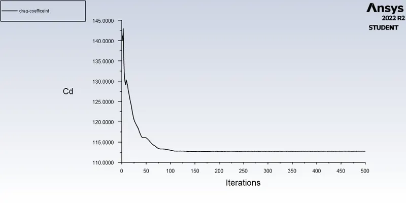
Aim- Perform an external flow simulation over a Ahmed body and plot the drag coefficient, vector plot and display the velocity and pressure contours, and perform a grid independence test.
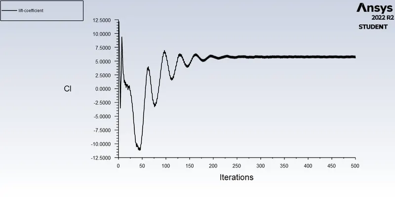
Objective- it is to determine the aerodynamic forces on the ahmed body such as drag coefficent, lift coefficient and perfrom a grid independence test.
Expected results are-
- Velocity and pressure contours.
- The drag coefficient plot for a refined cases
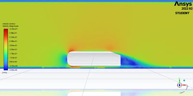
- The velocity plot clearly showing the wake region.
Abstract-
Ahmed body- The Ahmed body was created by S.R. Ahmed. It plays a important role in benchmark for aerodynamic simulation tools. The exact dimensional values of the ideal ahmed body is Length- 1.044 meters, height- 0.288 meters and the width- 0.389 meters. And the ahmed body has cylindrical shapes like legs on the bottom of the body which is used to replicate the wheels. And the rear end of the body has a slanted fall of 35 degrees.
Importance-
The drag force against the car body plays an important role while considering the fuel consumption of the vehicle. We can say that the drag force experiencing on the car body is directly proportional to the fuel consumption of the vehicle. The higher the drag the higher would be the fuel consumption thus lead to the making more expensive to maintain the car. As the burning of fossil fuel becomes an issue the car manufactures are keen to produce an fuel efficient car.
And now the cars geometry becomes more complex and it becomes difficult to quantify the aerodynamic drag computationally. So thus comes the Ahmed body as a benchmark model that is widely used in the automotive industry for the validating simulation tools.
Negative pressure in the wake region
When the air moving over the vehicle is separated at the rear end of the vehicle and leaves a large low pressure turbulent region which is known as wake region. This contributes to the formation of pressure of drag which affects the performance of the vehicle.
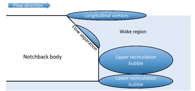
When the vehicle is moving at a certain velocity the fluid imports viscous force on to the vehicle as long as it is in the viscous sub layer of the boundary. When the fluid reaches the rea end it get detached form the surface of the causing negative pressure in the wake region. The moment of the fluid around the vehicles depend on the geometry of the car and Reynolds number.
Significance of point of separation
The point of separation will occur when there is a discontinuity in the surface or a region of the negative pressure gradient. When the flow is attached to the body of the vehicle the viscous force will increase which will increase the pressure and decrease the velocity before the rear end of the vehicle. As soon as the air encounters the sharp turn causing the velocity to increase and decrease the pressure resulting in the negative pressure region which is the wake region. The recirculation region happens beyond the point of separation.
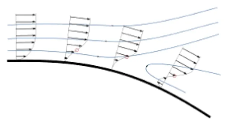
The above figure shows that at a point of turning the flow gets separated from the boundary layer and there is region of recirculation after which the flow attaches itself to the boundary layer.
In order to reduce the separation of fluid from the boundary layer it is advisable to have a smooth edge to reduce the effect on the drag of the vehicle.
Modelling Approach-
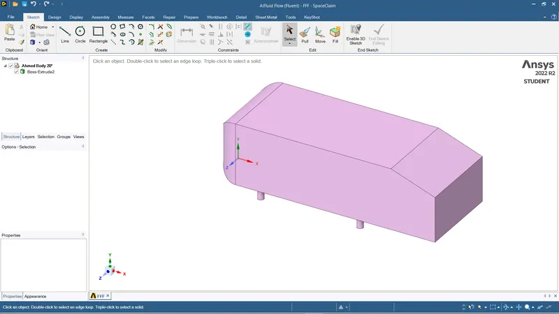
- Ahmed body is imported into the space claim.
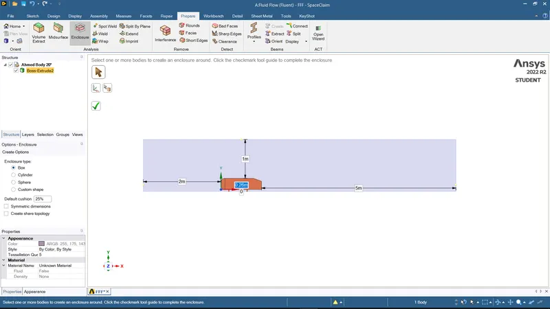
- An enclosure operation is performed on the ahmed body to extract the volume of the fluid domain. For that Steps are -- prepare- enclosure- select the body around which the enclosure should be performed. and then give the mentioned dimensions of the enclosure.
- Make the Ahmed body suppress for physics so that while meshing it will not cause any mesh overlap condition.
Meshing
- geometry is loaded for meshing.
- Name the faces as inlet, outlet, walls and Ahmed's body.
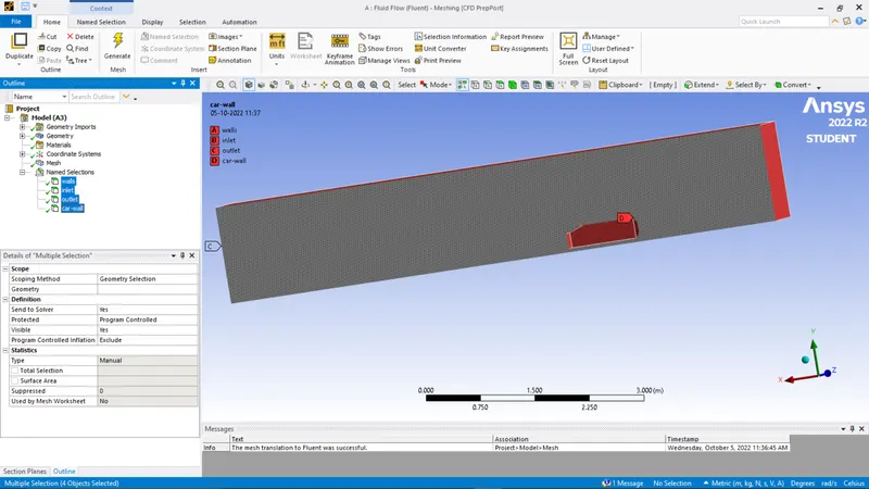
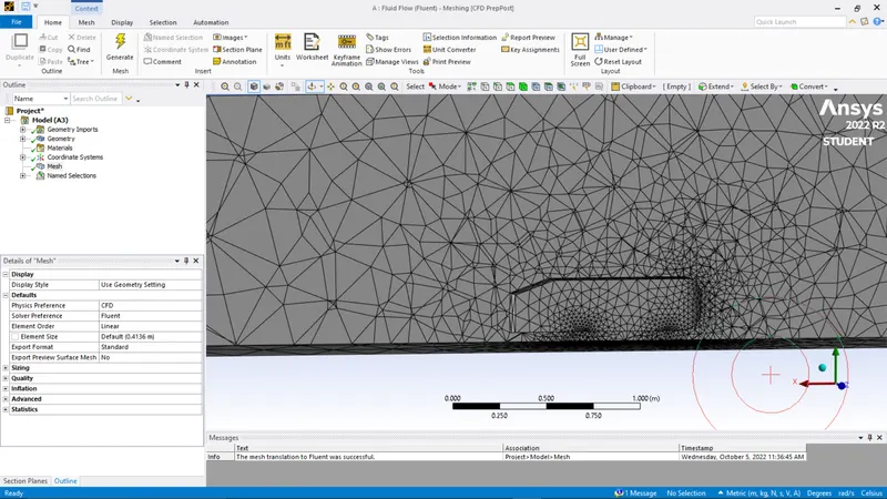
- a mesh element size is set to the default element size of ansys (413.6mm)
Ansys Fluent Setup
- Import the meshed geometry to the setup.
- Define all the parameters as-
- Make sure the solution method is set to the simple solution method.(this is the ideal parameter for running the simulation)
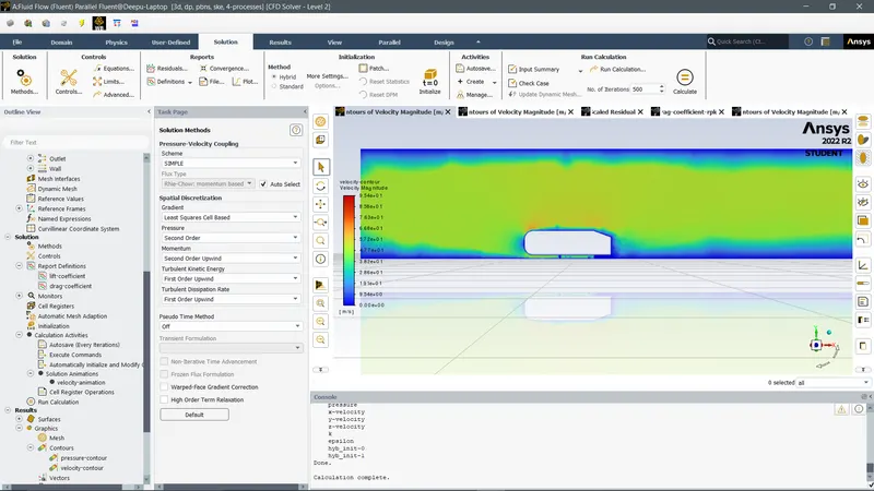
- Steady-state and the density-based solver and velocity formation should be in Absolute condition
- Will use the k-epsilon model for the viscous model.
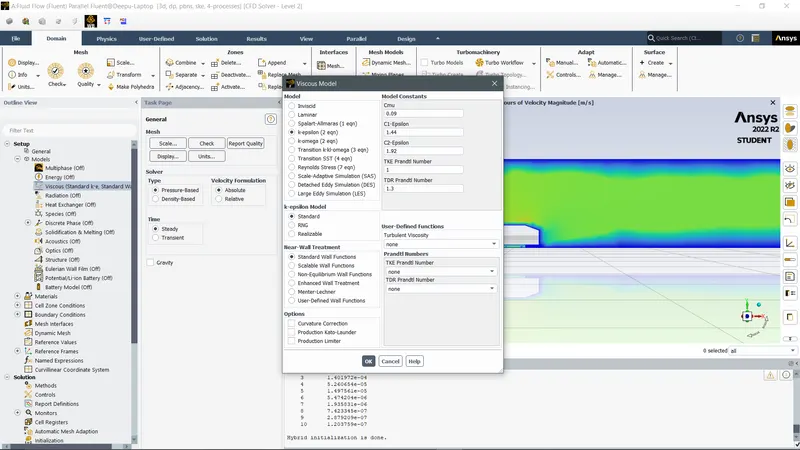
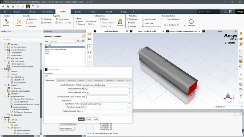
- For defining the boundary condition parameters---Inlet-25m/s, outlet- 0 gauge pressure, and walls- are the default properties as the fluent.
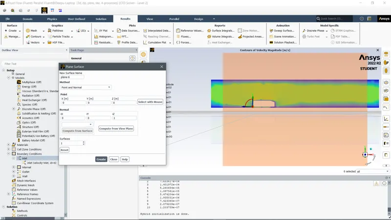
- Then create a cut plane on the z-axis to visualize and determine the act of velocity around the given geometry. For that steps are – Results- create- plane- points and normal- {points(x=0,y=0,z=0)& normal(x=0,y=0,z=1)}
- Now hit initialization t=o to initialize your mentioned parameters with the solution.
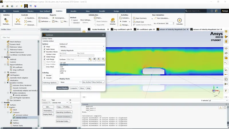
- Now as the plane is created we need to define a velocity contour by taking the plane-z as a reference.
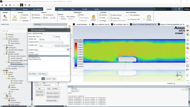
- As we want to analyse and visualize the simulation as live when the solution is been simulated we need to provide an animation tool on the plane.
For that ----Activities- solution animation- animation definition- select the velocity contour plot, to apply the animation on it.
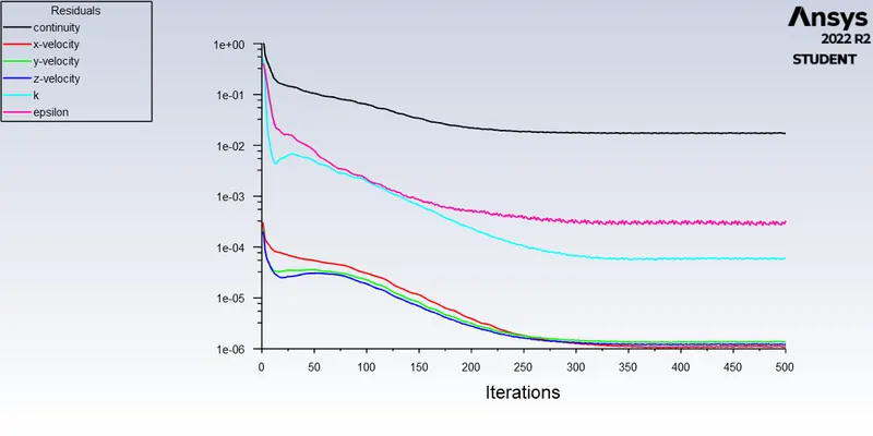
- Run the simulation for 500 iterations t=0 and analyse the result that occurs.
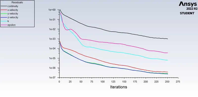
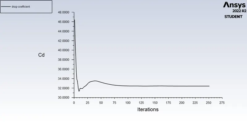
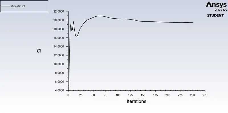
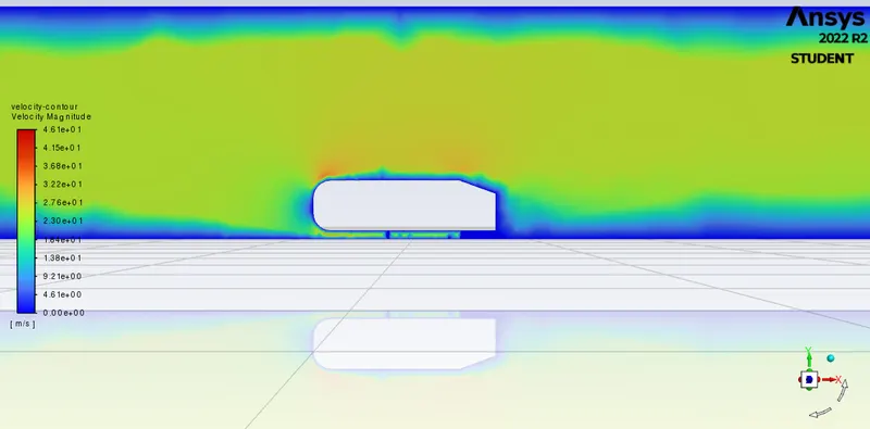
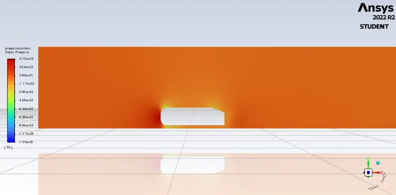
- Velocity and pressure contour are bit visually disturbing because of the lower mesh and single enclosure parameters.
- we can infer from the following outcome that the results of the base simulation don't capture much information efficiently such as turbulent flow, wake region, high velocity and low-velocity area so this problem can be solved further by using a much finer mesh. this occurs due to the enclosure is a bit large to capture all the information around Ahmed's body so it would provide more accurate results if the enclosure is a bit small and a bit closer to the surroundings of the body.
Case-2,
External flow simulation over Ahmed's body using a finer mesh with a double enclosure
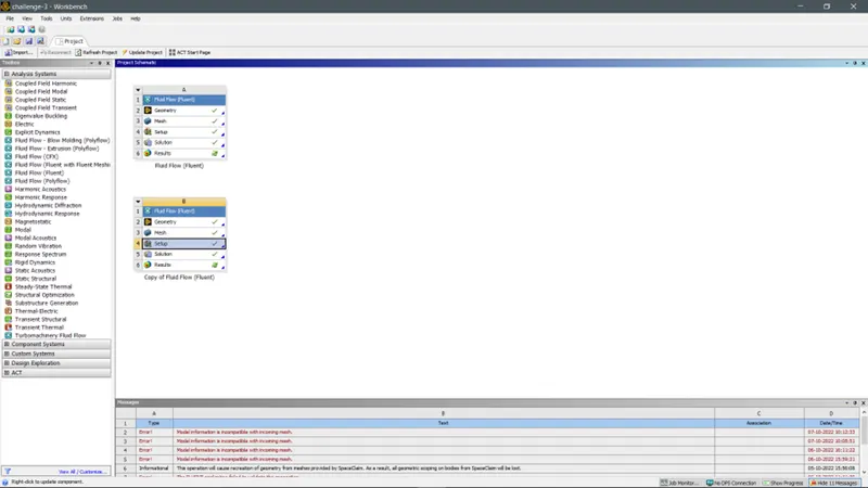
Duplicate the first simulation on the ansys workbench and edit the geometry using space claim to make double enclosure around the Ahmed body.
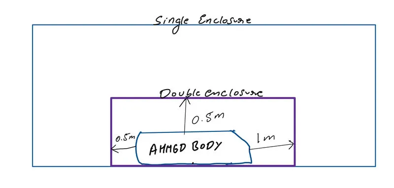
The dimension for the second enclosure are as follows-
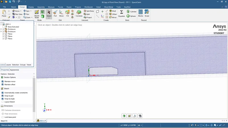
Make sure to check interference on the geometry so that the two enclosures don't react differently while meshing. And also share topology- share. so that the two enclosure geometry share the same topology identity.
On the meshing part, we perform the same mesh with some modifications such as-
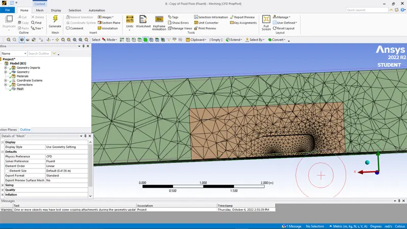
we applied multizone method on the outermost enclosure to provide hexahedral mesh which provides accurate result in simulation.
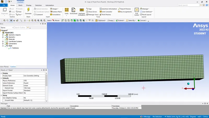
The element size is 50mm of the outer enclosure.
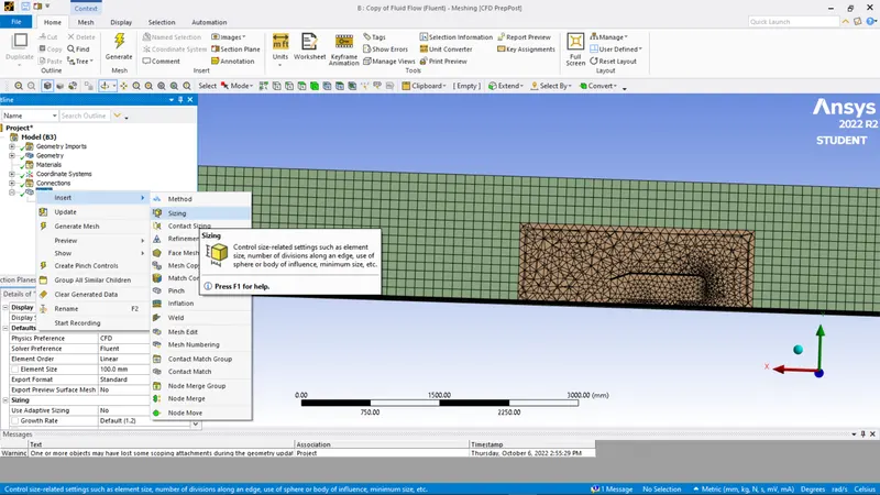
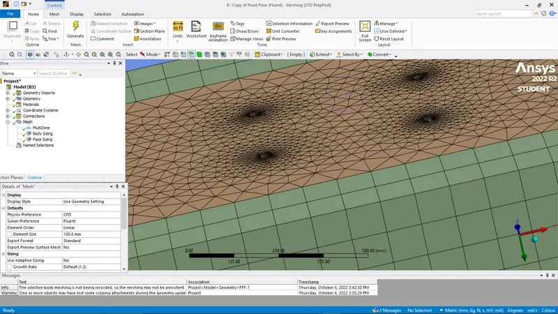
And we also provided an inflation layer on the Ahmed body geometry of 5 mm to define and refine edges of the geometry.