Week 3 - External flow simulation over an Ahmed body.
External flow simulation over an Ahmed body.
AIM:-
To study the external flow simulation over an Ahmed body.
THEORY:-
Ahmed Body
S.R. Ahmed first created the Ahmed Body in 1984. This geometry was used in his research “Some Salient Features of the Time-Averaged Ground Vehicle Wake”. The Ahmed body has a length of 1.044 meters, a height of 0.288 meters, a width of 0.389 meters, and 0.5-meter cylindrical legs attached to the body. Complex-shaped automobiles are very challenging to model and its difficult to quantify the aerodynamic drag computationally. The Ahmed body comes to our rescue in this scenario and can be used to validate simulation codes and studies.
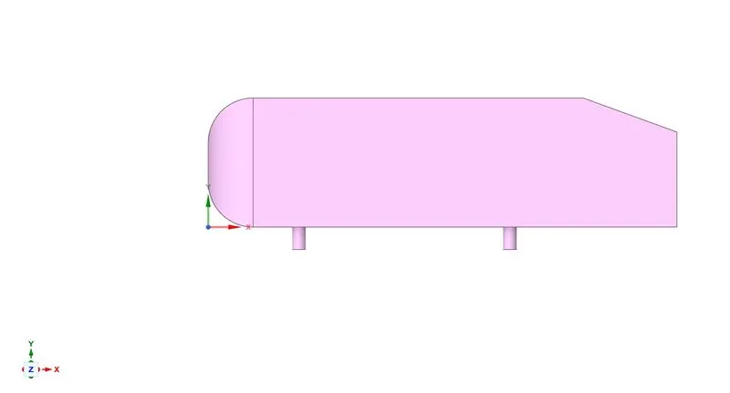
Wake region
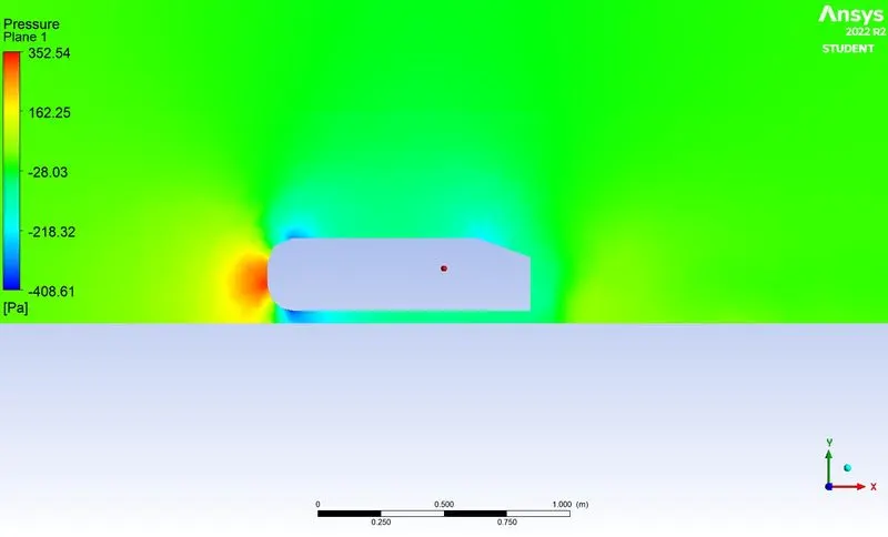
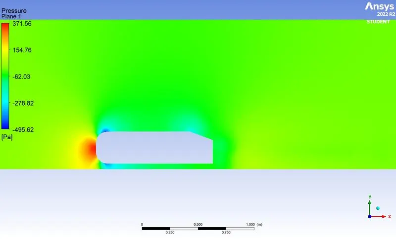
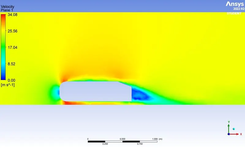
In fluid dynamics, a wake is a region of disturbed flow (usually turbulent) downstream of a solid body moving through a fluid, caused by the flow of the fluid around the body. In incompressible fluids (liquids) such as water, a bow wake is created when a watercraft moves through the medium; as the medium cannot be compressed, it must be displaced instead, resulting in a wave. This region contributes to pressure drag which affects the performance of the vehicle. The pressure inside the wake region remains low as the flow separates and a net pressure force (pressure drag) is produced. In other words, due to the production of pressure drag from flow separation, the pressure in the wake region is low.
Point of Separation
In flow-over cylinder simulation, it has been observed that when flow separates from the cylinder it creates vortices shedding which in turn induces cyclic loading. Similarly, flow separation increases the pressure drag due to negative pressure in the wake region. It also reduces lift force which is an important factor in aerodynamics. Thus it is required to delay the flow separation in order to delay the separation.
In order to reduce the separation of fluid from the boundary layer, it is advisable to have a smooth edge to reduce the effect of drag on the vehicle.
MODELLING APPROACH:-
- The geometry (Ahmed's body) is imported to the Spaceclaim.
- Two enclosures are drawn across the Ahmed body. One is for the entire fluid domain and the other one is created near the body to capture the wake region more efficiently
- Split body geometry can be used as the body is symmetrical and it will save a lot of computational time
- The simulation is carried out for 3 different mesh element sizes starting from 250mm for the outer enclosure and 100mm for the inner enclosure.
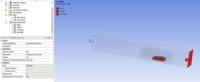
- Named selections are created for the enclosure viz; inlet, outlet, symmetry, and car wall.
- For simulation, the steady-state and pressure-based solver is selected.
- Reference values are updated as per the problem statement. The inlet velocity is 25m/s.
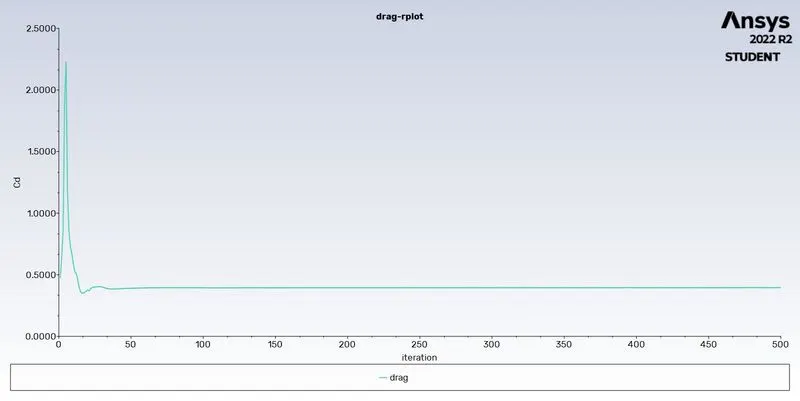
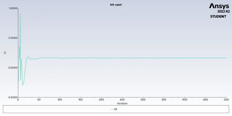
- Report definitions are created for the drag coefficient and lift coefficient. Hybrid initialization is selected and the simulation is run for 500 iterations.
- Necessary contour plots and vector plots are obtained from the post-processing.
PRE-PROCESSING:-
Geometry
- Import the geometry to Spaceclaim.
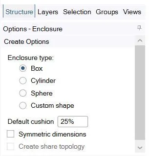
- Create enclosures using the Enclosure tool. Uncheck the symmetry option and give dimensions as per the problem statement.
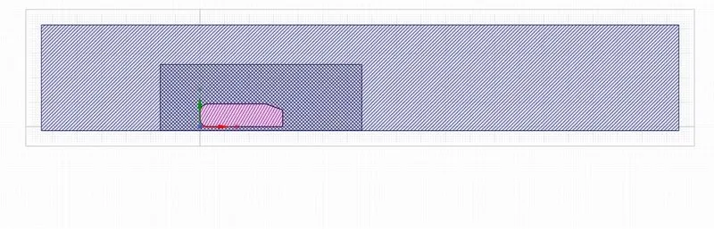
- Check for ant interference and rectify it using the Interference option.
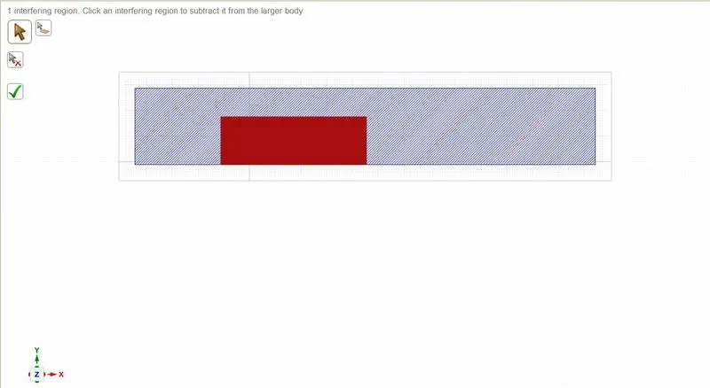
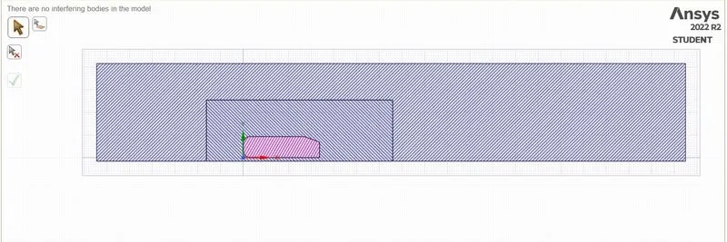
- Use the Share tool for sharing topology.
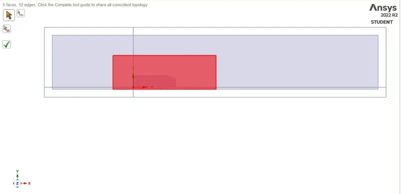
- Split the body using the Split body command.
Meshing
- Generate mesh with a base element size of 250mm.
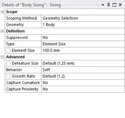
- Provide body sizing for the inner enclosure.
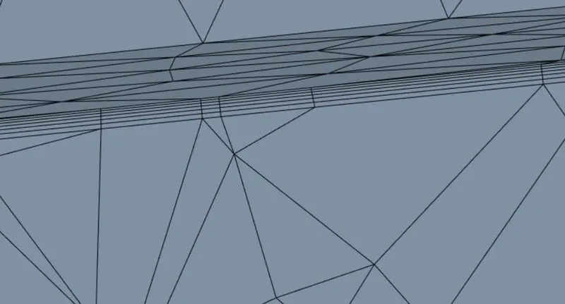
- Create an inflation layer with a first layer thickness of 0.4mm.
- Use face sizing for the legs with an element size of 2mm
- Create named selections.
Setup
| 1. | Solver type | Pressure based |
| 2. | Solver time | Steady-state |
| 3. | Energy | Off |
| 4. | Turbulence Model | K epsilon |
| 5. | Material | Air |
| 6. | Inlet | Inlet velocity - 25m/s |
| 7. | Outlet | Pressure outlet |
| 8. | Car Wall | Wall BC |
| 9. | Side faces of the enclosure | Symmetry BC |
| 10. | Method | Coupled |
RESULTS
Case 1
- Base mesh element size - 250mm
- Body sizing - 100mm
- Face sizing - 2mm
- Number of elements - 143267
Plots
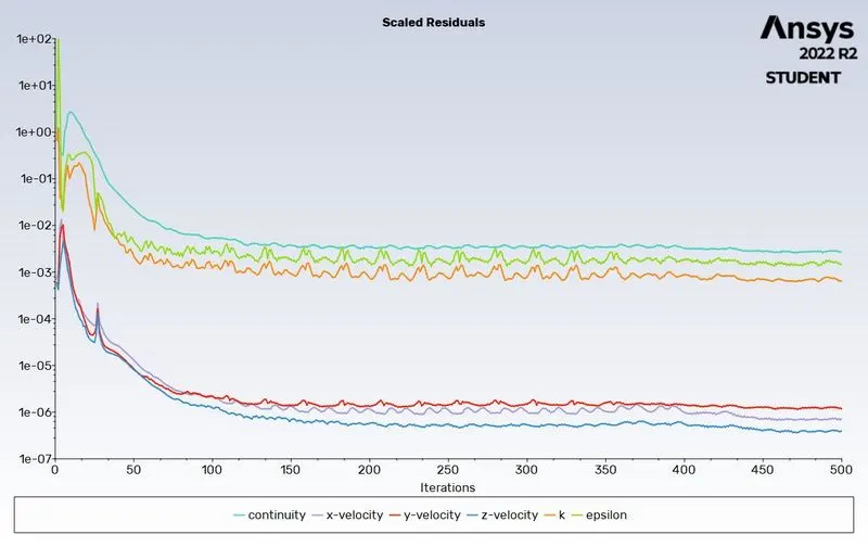
- Residuals
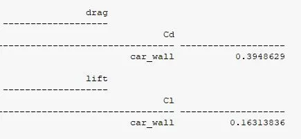
- Drag
- Lift
- Drag coefficient
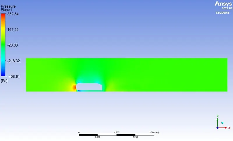
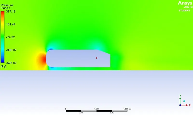
- Pressure contour
- Pressure contour near wake region
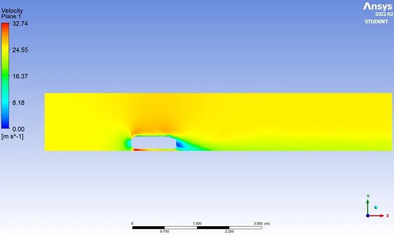
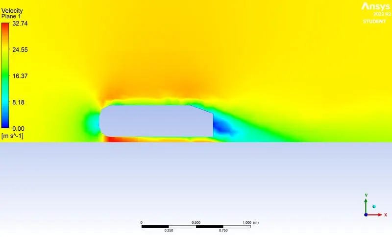
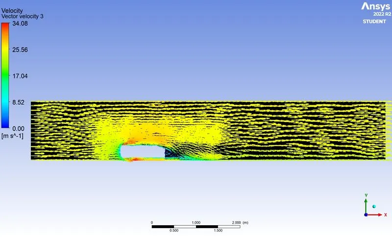
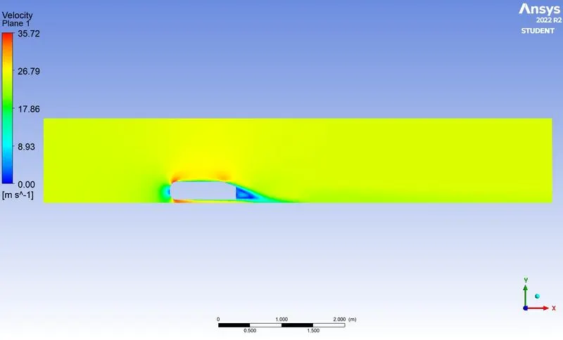
- Velocity contour
- Wake region
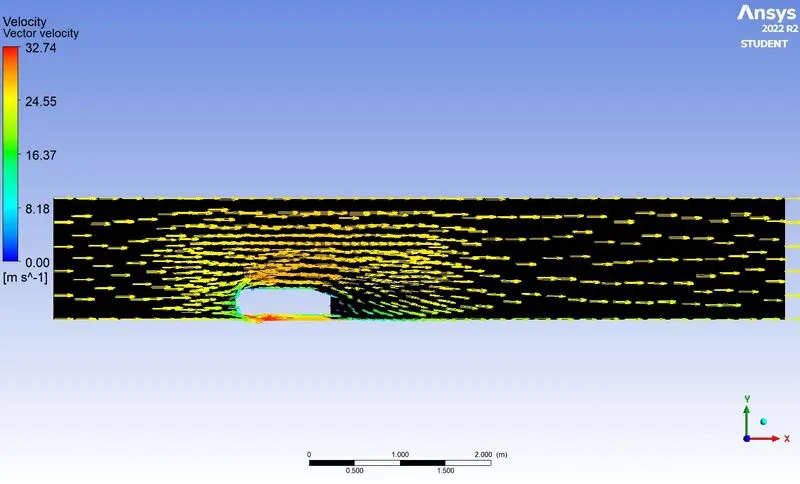
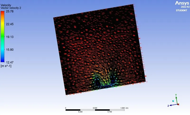
- Velocity vector plot
XY plane
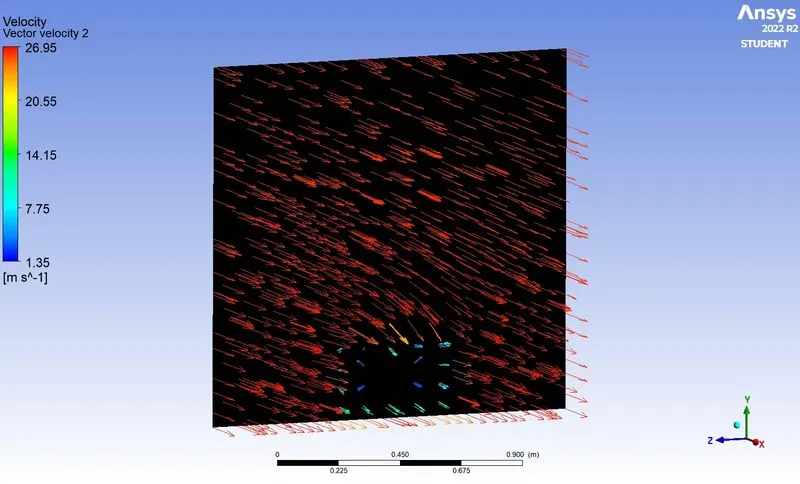
Rear end of the body
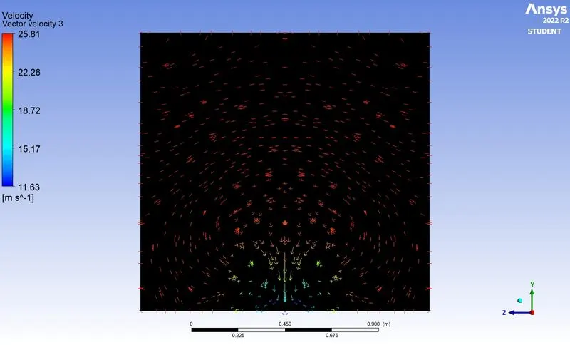
1.5m from the rear end
Case 2
- Base mesh element size - 100mm
- Body sizing - 50mm
- Face sizing - 2mm
- Number of elements - 259257
Plots
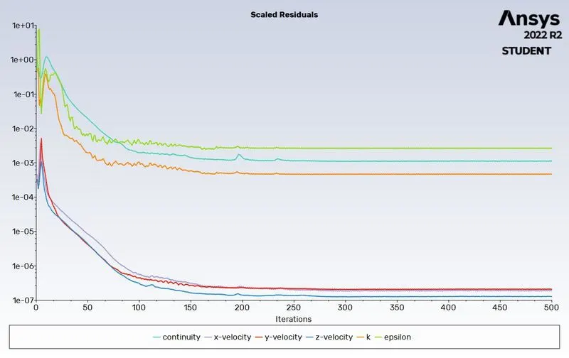
- Residuals
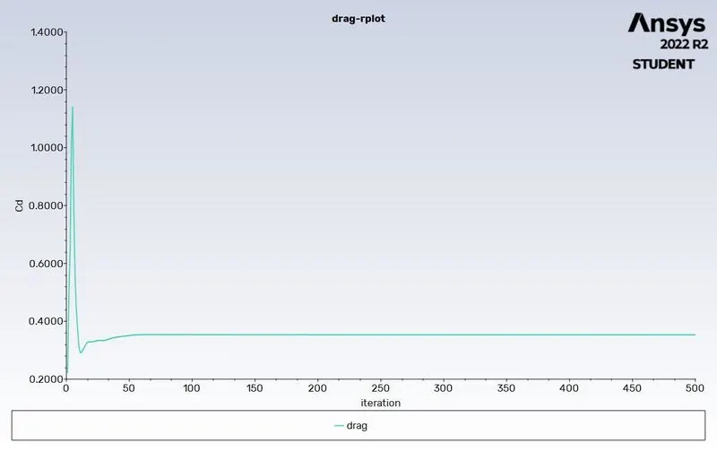
- Drag
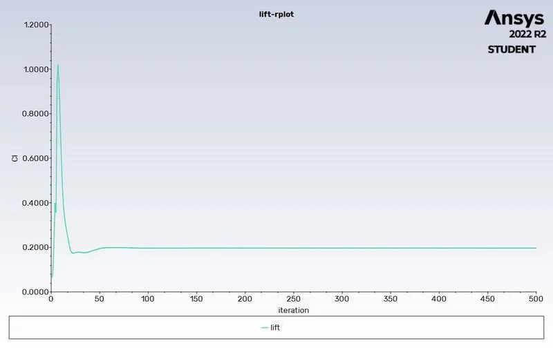
- Lift
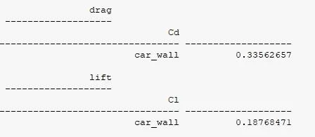
- Drag coefficient
- Pressure contour
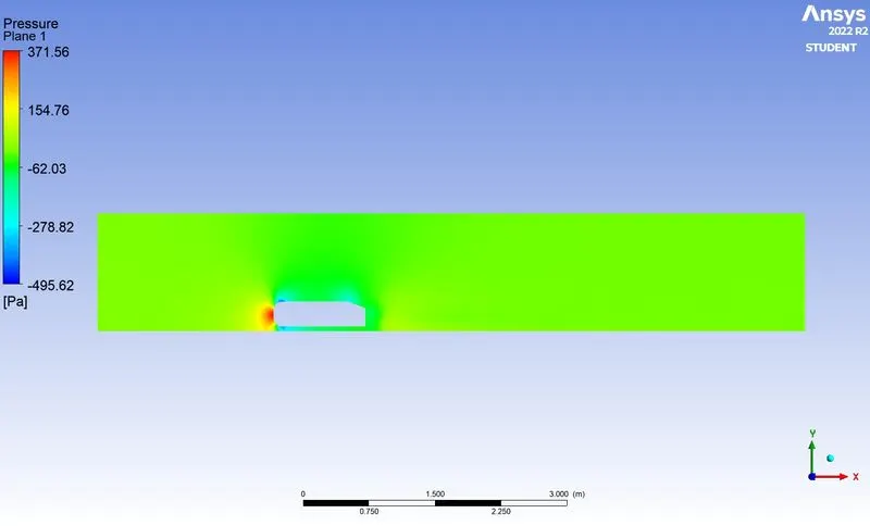
- Pressure near the wake region
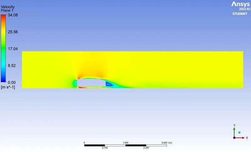
- Velocity contour
- Wake region
-
- Velocity vector plot
XY plane
Rear end of the body
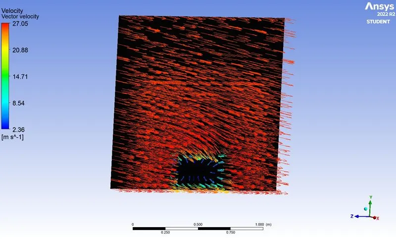
1.5m from the rear end
Case 3
- Base mesh element size - 80mm
- Body sizing - 35mm
- Face sizing - 2mm
- Number of elements - 404893
Plots
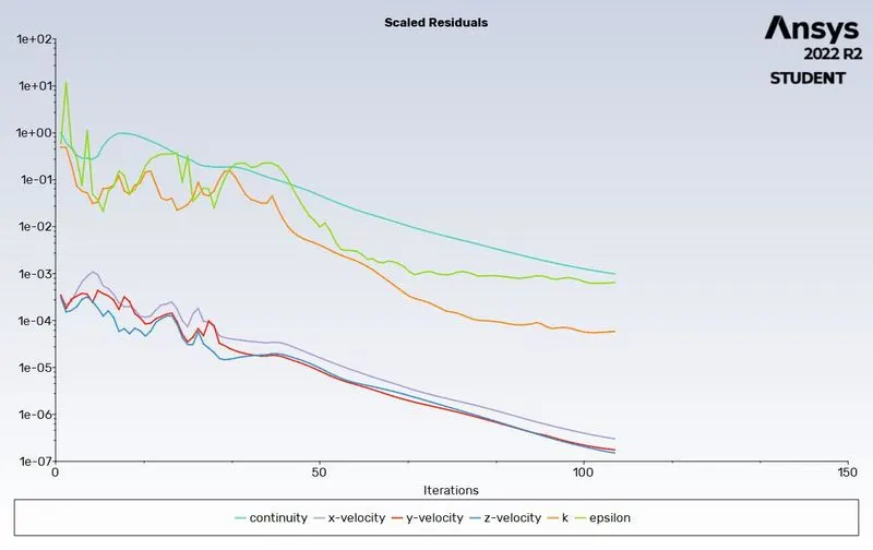
- Residuals
- Drag
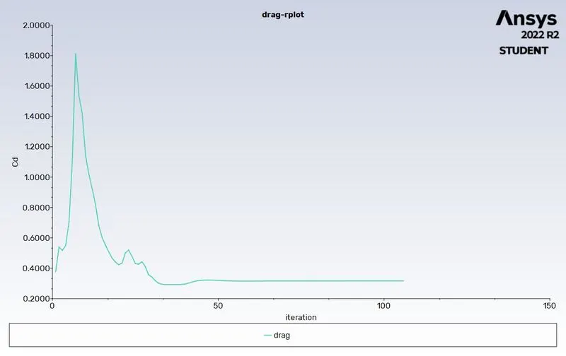
- Lift
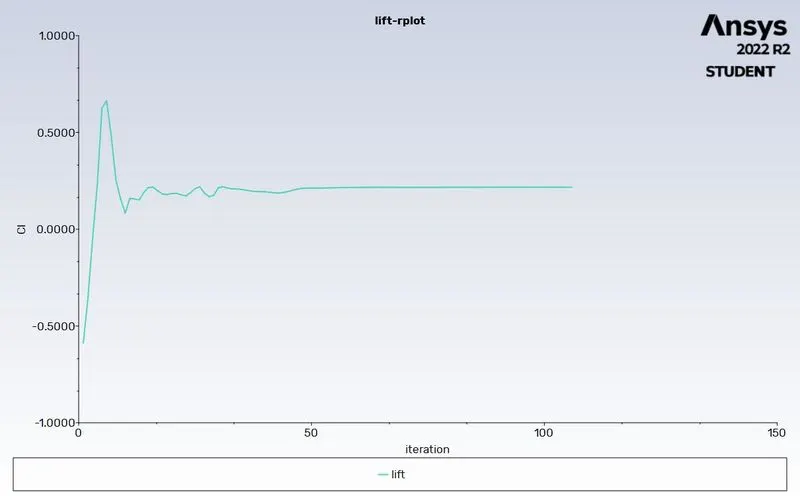
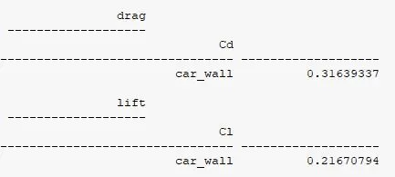
- Drag coefficient
- Pressure contour
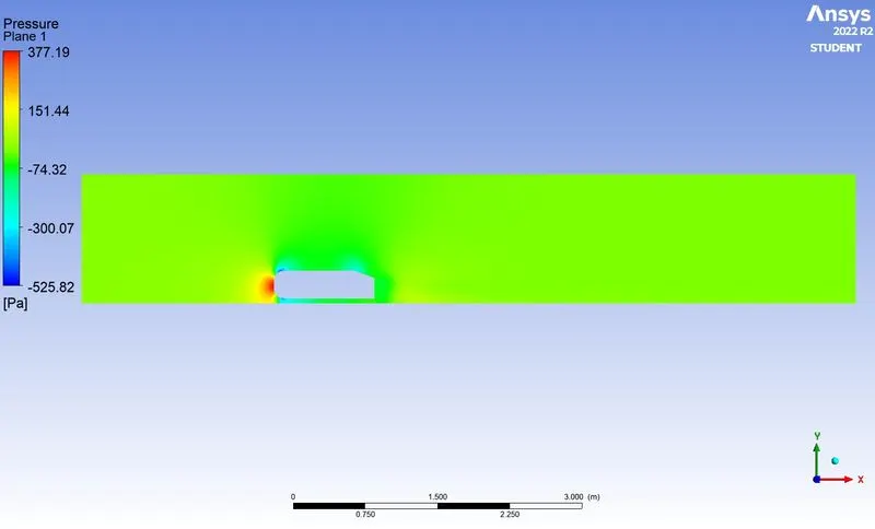
- Pressure near the wake region
- Velocity contour
- Wake region
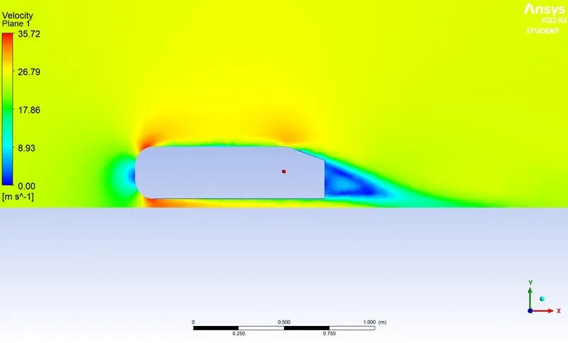
-
- Velocity vector plot
XY plane
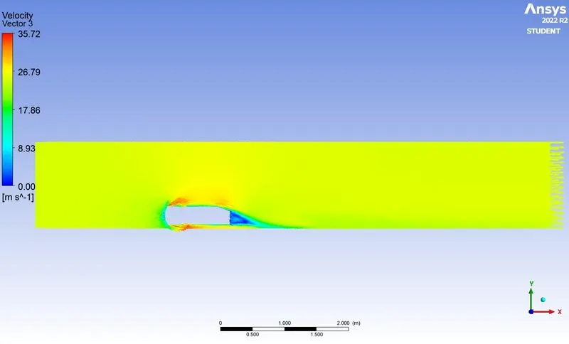
Rear end of the body
1.5m from the rear end
- Grid independence study and comparison of Drag coefficient values
CONCLUSIONS
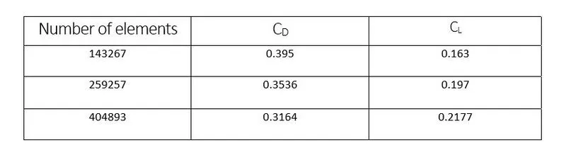
- For a velocity of 25m/sec, the drag coefficient should be around 0.33 from the experimental results. Here we got a value of 0.319 with a finer mesh size. It nearly matches the experimental value
- Flow separation can be easily visualized by observing Pressure and Velocity contours.
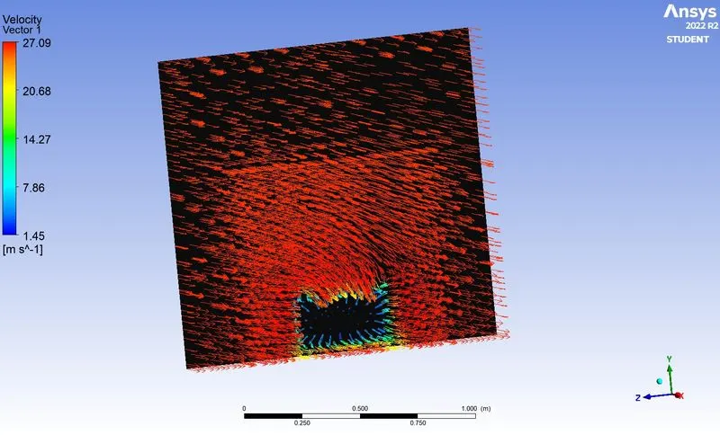
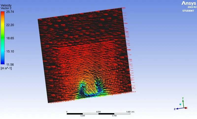
- The point of separation occurs at the rear end of the vehicle and at a particular distance the flow recirculates and attaches it to the boundary layer. This can be observed from the velocity vector plots.
- A decrease in the value of the drag coefficient is observed when the mesh size is decreased.