Week 2 Challenge : Surface meshing on a Pressure valve
Surface meshing on a Pressure valve
Aim:- To generate surface mesh on a Pressure valve with target lengths of 1mm, 3mm, and 5mm. The element type should be TRIA.
Procedure:-
- Import the required ANSA file of the Pressure valve on which meshing has to be done.
- Conduct a geometry check using the "Check" option from MENUBAR.
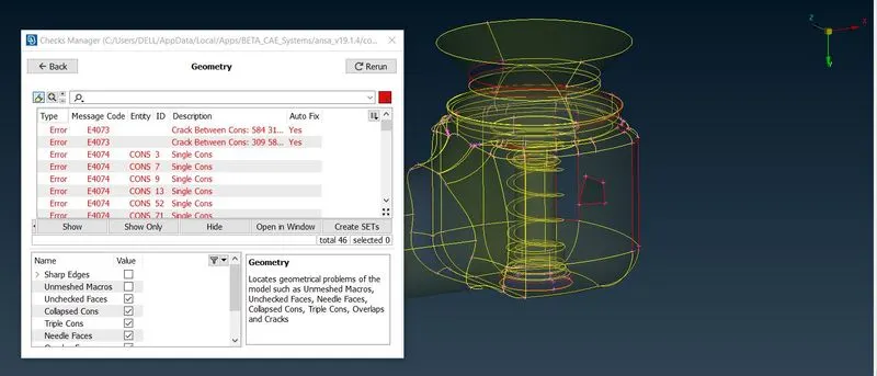
- Turn on the shadow mode for better geometry understanding.
- Using any one of the options from the Topo module, geometry cleanup can be done on the model.
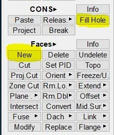
- "New" tool under the Faces section.
- "Fill Hole" tool under the CONS section.
Both tools can be used interchangeably according to the requirement.
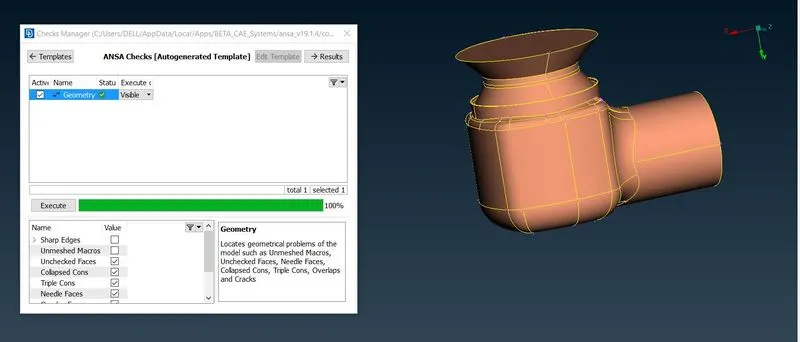
- Conduct a geometry check after the cleanup to ensure the process was done correctly.
- Now we can assign PIDs to different parts of the Pressure valve. This can be done by using the "Properties" option from MENUBAR. A pop-up window will be opened when you click that option.
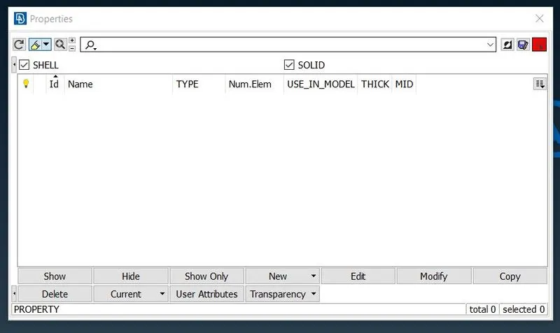
Select the "New" option from the bottom of the screen and create a new PID with an appropriate name. This has to be done as long as we have the required PIDs.
Right-click the PID name and select "Apply". Then the part to be assigned is selected and the middle mouse button is clicked. This will assign that PID name to the selected part.
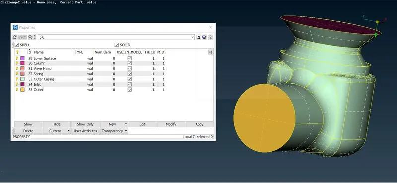
- Assign the Mesh criteria and the Quality criteria. For the first case max. target length is 5mm.
- Use the "Length" option to assign the target length for Macros and Perimeter.
- Use the "Spot Mesh" tool to generate mesh on the entire model.
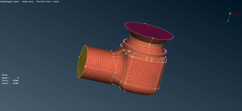
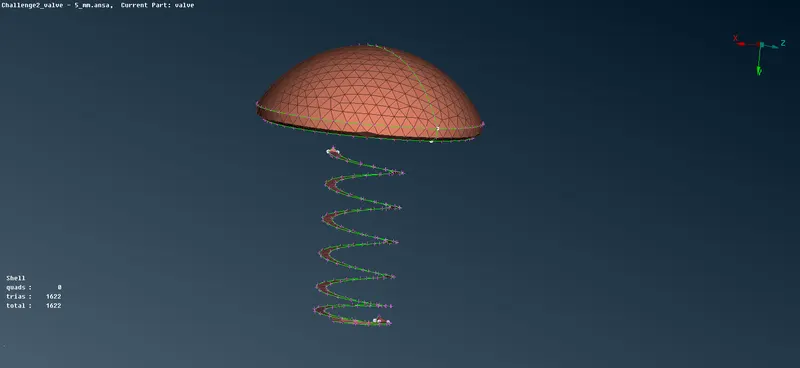
From the above image, we can see that after meshing the shape of the spring has been changed to 2-dimensional and the meshing on the valve head is irregular.
This is because the spring diameter is smaller than the target length of 5mm (approx. 3.5mm). In order to rectify this, we can assign separate target lengths to the valve head and spring so that a better mesh can be generated. We can assign the target length as 1mm for this case. The mesh is erased and a new one is created as per the above step.
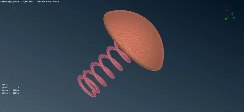
Now we can see that the meshing was done correctly and there is no shape change.
- The same procedure is conducted for both 3mm and 1mm target lengths. But in both cases the Spring and Valve head target length is assigned as 1mm for a better result.
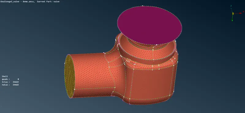
3mm target length meshing
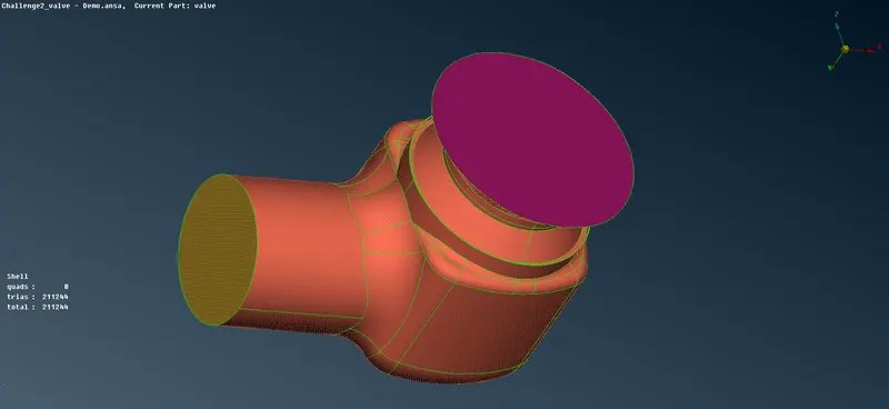
1 mm target length meshing
Learning Outcomes:-
- Geometry cleanup
- Assigning PIDs to different parts
- Selecting the Mesh parameters and Quality criteria according to the available geometry for accurate results.
- Fine mesh takes more time compared to coarse mesh.
Result:-
3 different meshes have been generated as per the target lengths of 5mm, 3mm, and 1mm. The target length of 1mm has been kept constant for the spring and valve head to get accurate results.
Conclusion:-
While giving meshing parameters and quality criteria, the geometry of the mesh should be taken into consideration so that inaccurate mesh generation can be prevented
The compressed RAR file is attached separately.