Week 3 - External flow simulation over an Ahmed body.
The Ahmed body is a generic car body (a simplified vehicle model). The airflow around the Ahmed body captures the essential flow features around an automobile and was first defined and characterized in the experimental work of Ahmed [1]. Although it has a very simple shape, Ahmed body allows us to capture characteristic features that are relevant to bodies in the automobile industry.
This model is also used to describe the turbulent flow field around a car-like geometry. Once the numerical model in validated, it is used to design new models of the car.
Geometry-
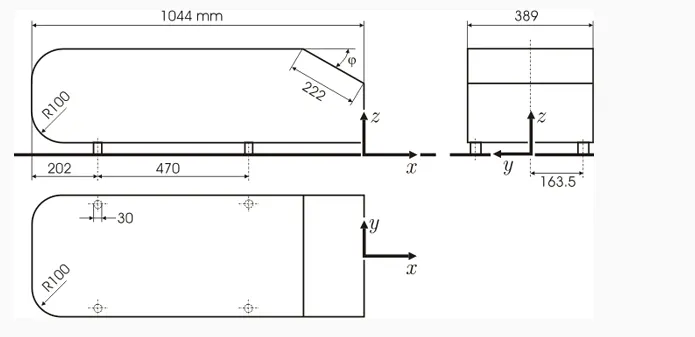
The Simulation on the Ahmed body on ansys gives the output as:
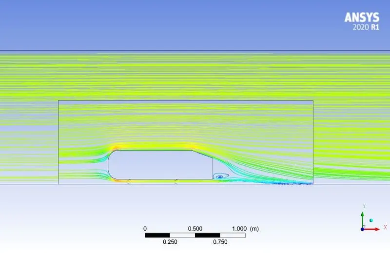
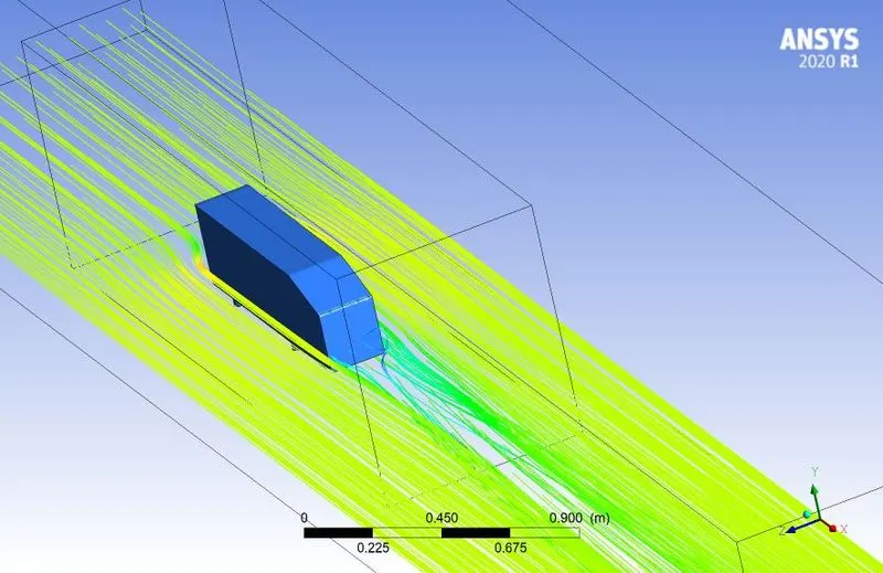
Wake region:
Flow separation:
Flow separation or boundary layer separation is the detachment of a boundary layer from a surface into a wake. Separation occurs in flow that is slowing down, with pressure increasing, after passing the thickest part of a streamline body or passing through a widening passage, for example.
Flowing against an increasing pressure is known as flowing in an adverse pressure gradient. The boundary layer separates when it has travelled far enough in an adverse pressure gradient that the speed of the boundary layer relative to the surface has stopped and reversed direction. The flow becomes detached from the surface, and instead takes the forms of eddies and vortices. The fluid exerts a constant pressure on the surface once it has separated instead of a continually increasing pressure if still attached. In aerodynamics, flow separation results in reduced lift and increased pressure drag, caused by the pressure differential between the front and rear surfaces of the object. It causes buffeting of aircraft structures and control surfaces.
The complete modelling of this case setup is explained as below:
Initially the model is imported in the space claim file and te enclosures are made as specific to wake region. And the models topology is set to share in this.
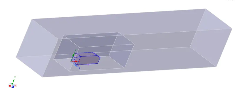
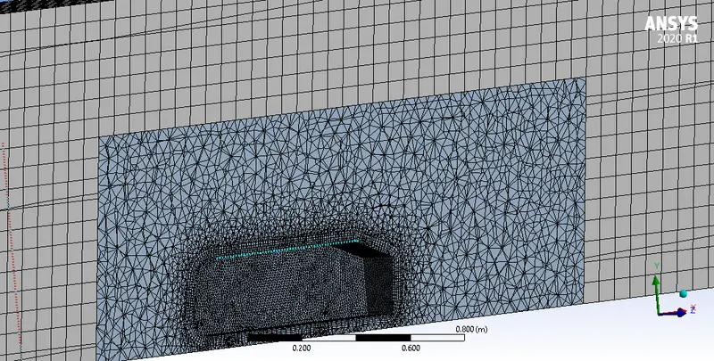
Then the meshing is done on the both the enclosures and different mesh sizes are alloted to both of the enclosures. The basic detailing of each mesh is shown as below
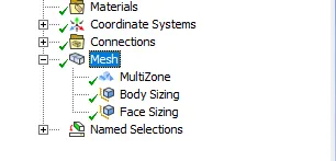
The sample mesh of one case is obtained as shown below:
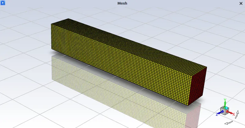
The simulation case setup is done as below:
The Refrence values for the simulations are given as below
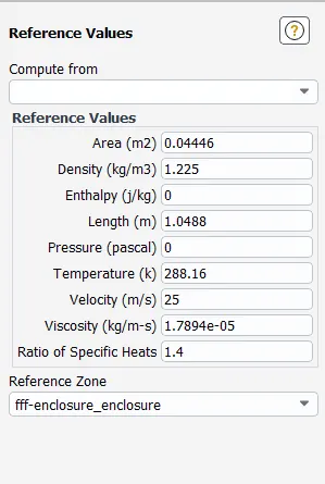
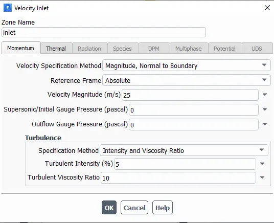
The face assigned as inlet is given a inlet velocity of 25m/s.
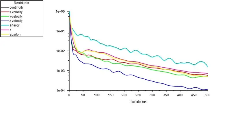
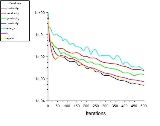
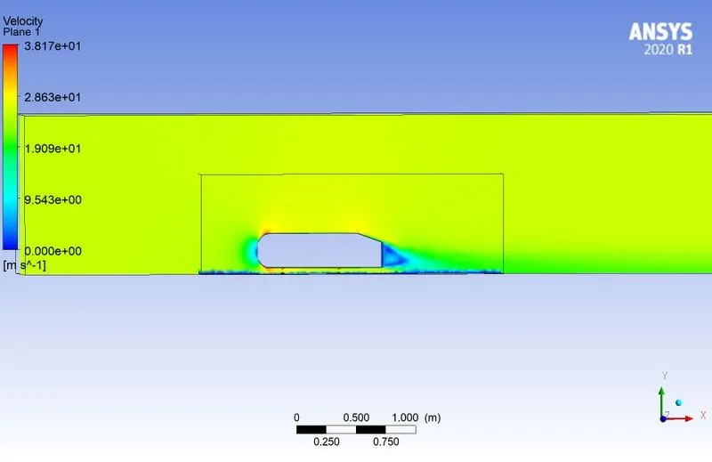
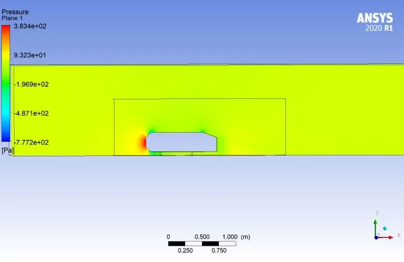
The Simulation is run for 500 iterations for different global mesh sze. The results are:
1. 0.08m mesh size:
2. 0.1m mesh size
3. 0.25m mesh size:
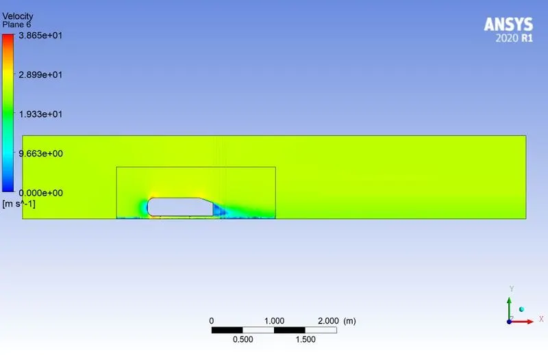
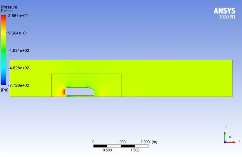
From the above results
1. it is observed that the residuals are in a smooth pattern i.e. the case setup was made correct.
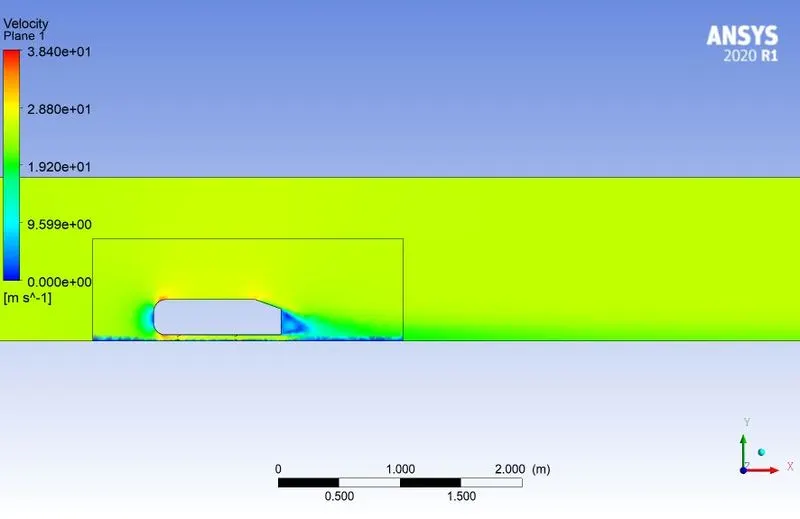
2. There is velocity mixing in the wake region.
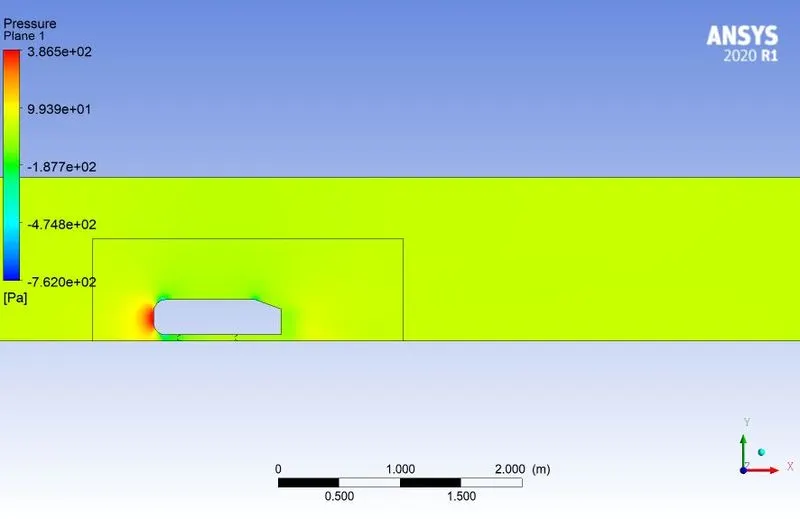
3. Also in the wake region the pressure has a negative value which eventually leads to the drag force.
The wake region formation is observed at 4 different planes with velocity vectors at a distance of 1.06, 1.1, 1.2, 1.25 m.
1st plane-
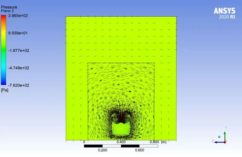
2nd plane-
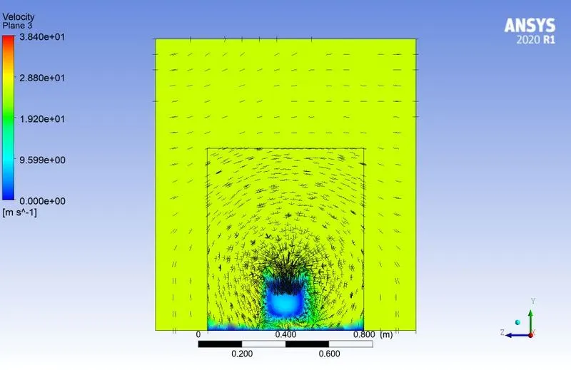
3rd plane-
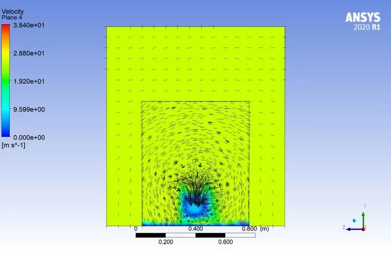
4th plane-
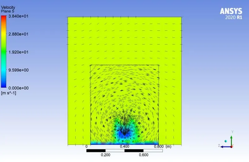
5th plane-
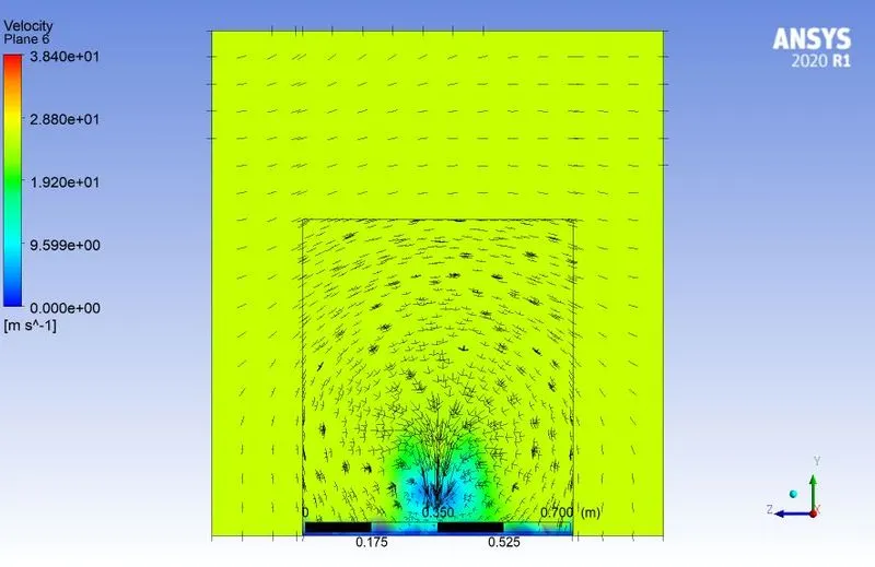
The drag and lift coefficient at different mesh sizes
| Mesh size | Cd | Cl |
| 0.08m | 0.46940739 | 0.26834275 |
| 0.1m | 0.47034398 | 0.24079502 |
| 0.25m | 0.45613309 | 0.27829607 |
There is no significant change in the values, so we can say that this it is grid indipendent.