Week 3 - External flow simulation over an Ahmed body.
Aim : To simulate 2D flow over Ahmed body to study Coefficient of Drag, Lift, Velocity , Pressure, Streamlines and wake generation around it. Using Ansys Fluent as the simulation tool we will look into the Boundary layer formation around the Ahmed body.
Ahmed body and its Importance:
- Ahmed body is a bluff body which is used to study the external aerodynamics of the vehicles. The flow over the geometrically similar Ahmed body act as the reference in order to validate the actual numerical simulation.
- Ahmed body is a simplified car shaped made up of parallelopiped with round edges at the front and slant face at the rear. This slant face causes the flow separation to occur and also plays a major role in deciding the coefficient of Drag & Lift.
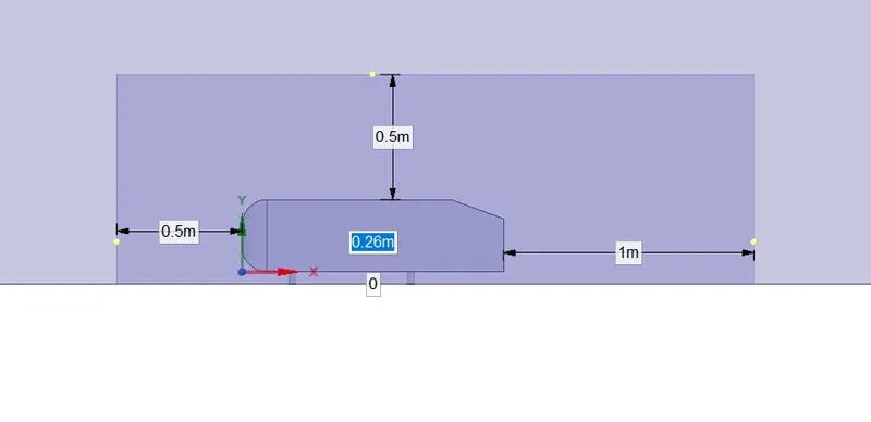
- The Ahmed body has a Length of 1.044m, Height of 0.288m, width of 0.389m. It also has 0.5m cylindrical legs attached at the bottom of the body. The rear slant is at 40-degree inclination.
- In order to study the various geometry and it is effect over flow dynamics is very vital in improving the fuel efficiency and optimising the design of the vehicle by minimising the wake and flow separation.
- As we have rich experimental data associated with Ahmed body, so studying the wake and vortices at the rear of the vehicle using Numerical Method is possible.
Baseline Simulation:
- Import the Ahmed body file into the Ansys Geometry.
- In order to create the wind tunnel, click Prepare, then Enclosure, Unsymmetric. This helps to make the mesh around the around the Ahmed body.
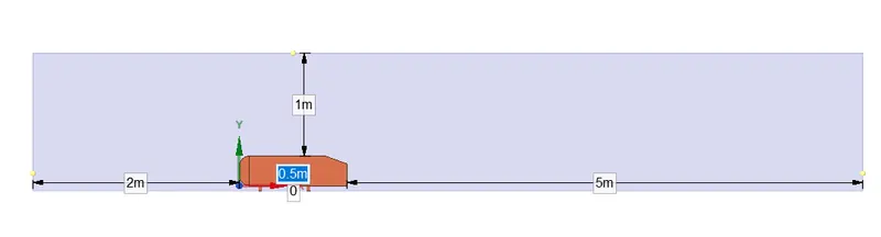
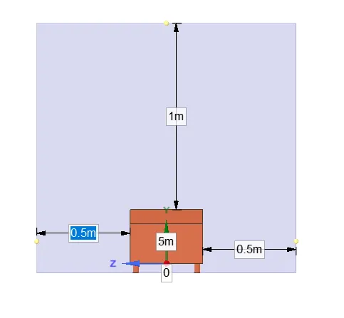
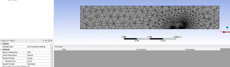
- In the Ansys Mesh select the element size to be 0.4m. Name the boundaries by selecting the faces and clicking on N.
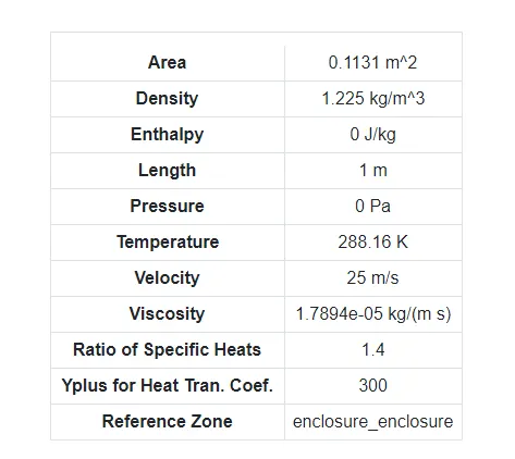
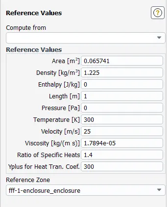
- In Ansys Setup change the Reference values accordingly. Then select the working fluid to be air, Turbulence model to be K-Epsilon Realisable model. Inlet velocity to be 25m/s.
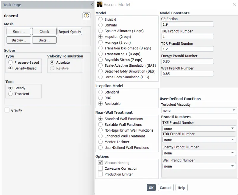
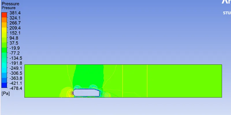
- Generate report plot for coefficient of Drag & Lift, Contour plots of Velocity and pressure.
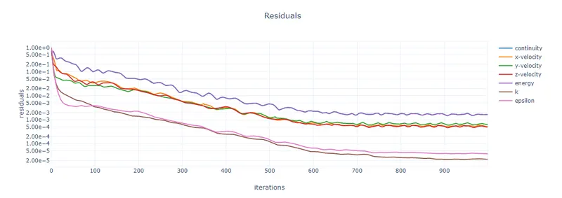
Residual Plot:
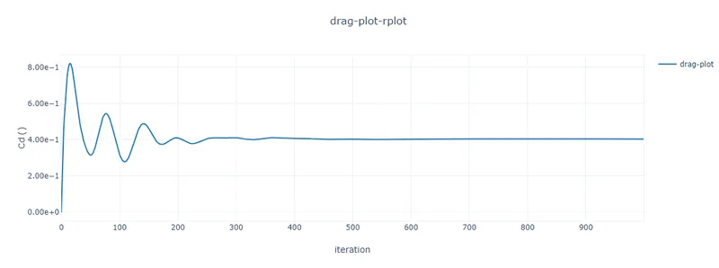
Drag Plot:
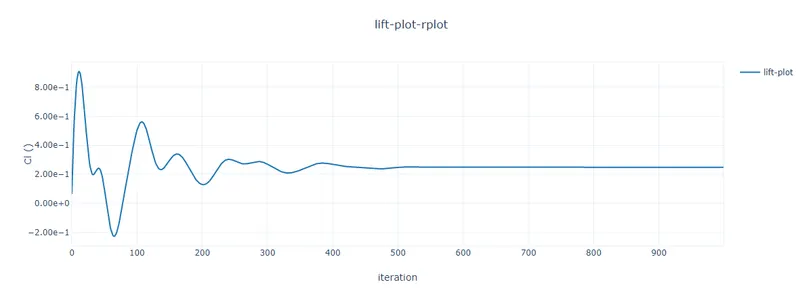
Lift Plot:
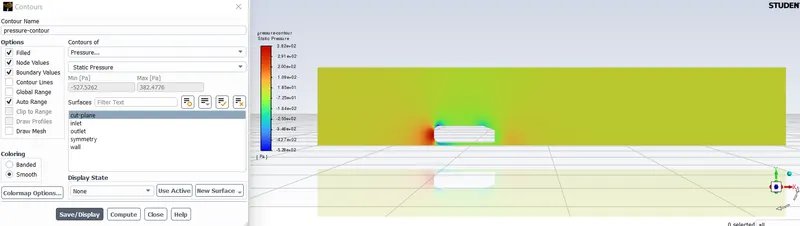
Pressure Contour:
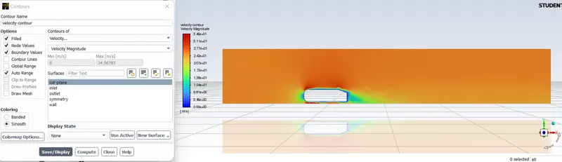
Velocity Contour:
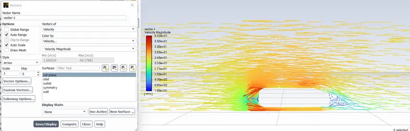
Streamline along Ahmed Body:
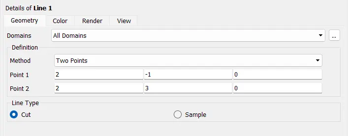
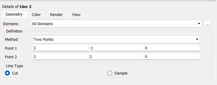
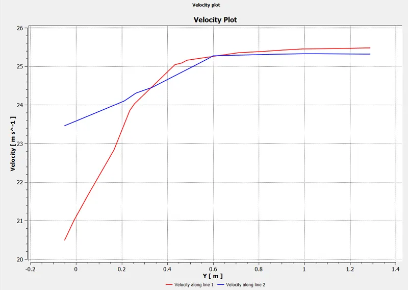
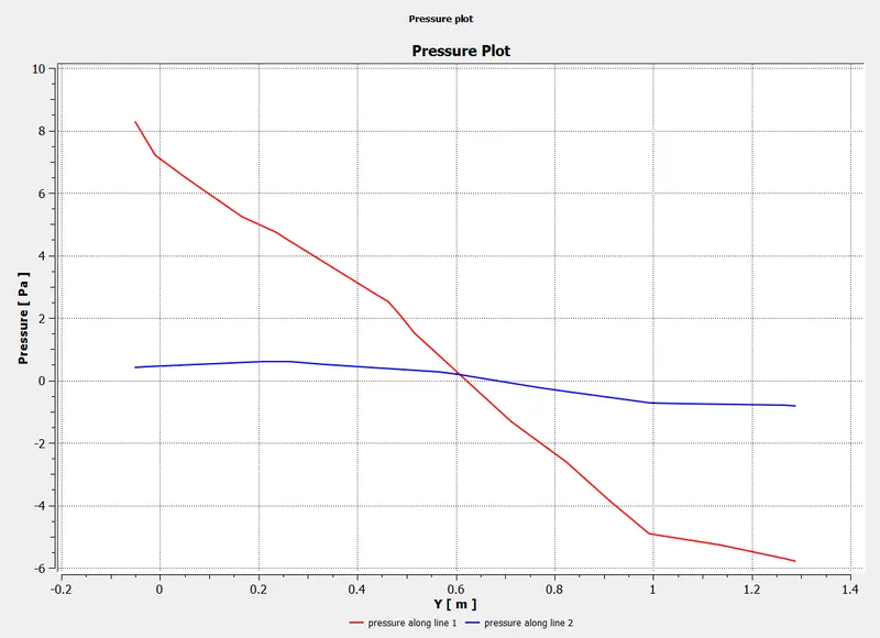
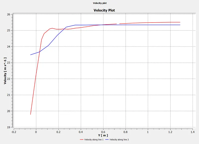
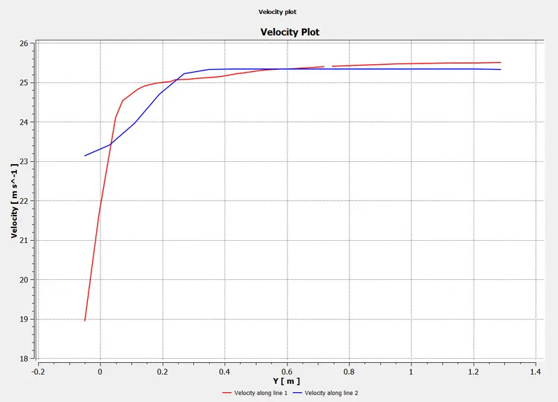
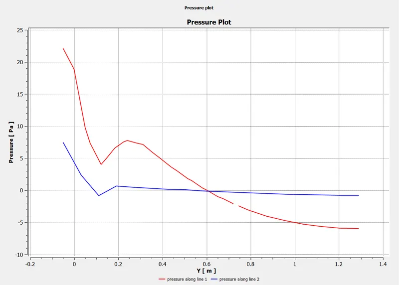
- Post processing :In order to plot the velocity and pressure at the wake region two lines are placed and the data collected is plotted in graph.
Velocity Plot:
Pressure Plot:
Pressure Contour:
Velocity Contour:
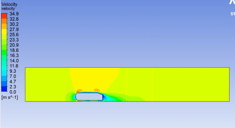
Result_1:
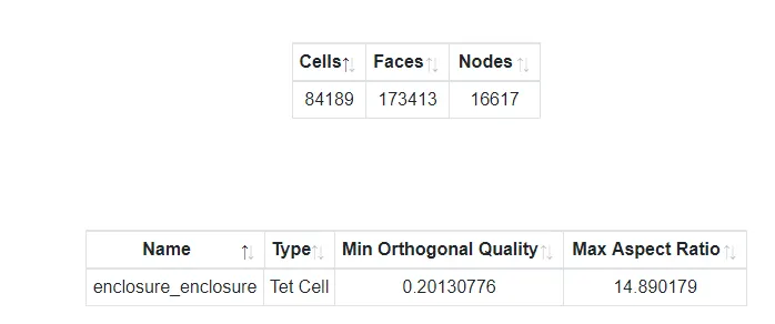
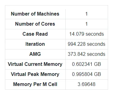
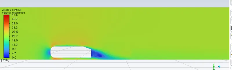
- From the above results it is concluded that the mesh needs to be refined along the Ahmed body using Inflation tool.
- As the K-Epsilon model over estimates the boundary layer separation and along is less competent in dealing with wake and vortices, so K-Omega turbulence model is used.
Y+ Calculation: Calculating the total inflation layer thickness for Y+=100
`Re=(rho*V*L)/mu=(1.225*25*1.044)/(1.789*10^-5)=1787171.6`
`coefficient of Friction (Cf)=0.026/(Re)^(1/7)=0.026/1787171.6=0.003325`
Wall Shear Stress `(tauw)=(Cf*rho*V^2)/2=1.2728`
`muf=((tauw)/rho)^(1/2)=1.01932`
First layer thickness (y)= `(Y^+*mu)/(muf*rho)=(100*1.789*10^-5)/(1.01932*1.225)=0.00143`
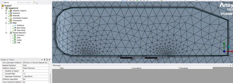
Using first layer thickness causes some parts of edge to skew so, we would be using total layer thickness for 6 layers.
Total Layer Thickness= `Sn=(a*(r^n-1))/(r-1)=(0.00143*(1.2^6-1))/(1.2-1)=0.0142`
Simulation for Y+=300:
Geometry:
- It is essentential that there is need for refining the wake and near wall region to estimate the Drag and Lift coefficient.
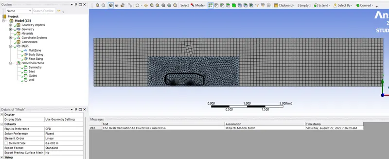
- But by doing so we might increase the no. of cells, so we split the Ahmed body along the mid plane and enclose it within another enclosure and refine it further more then the outside enclosue.
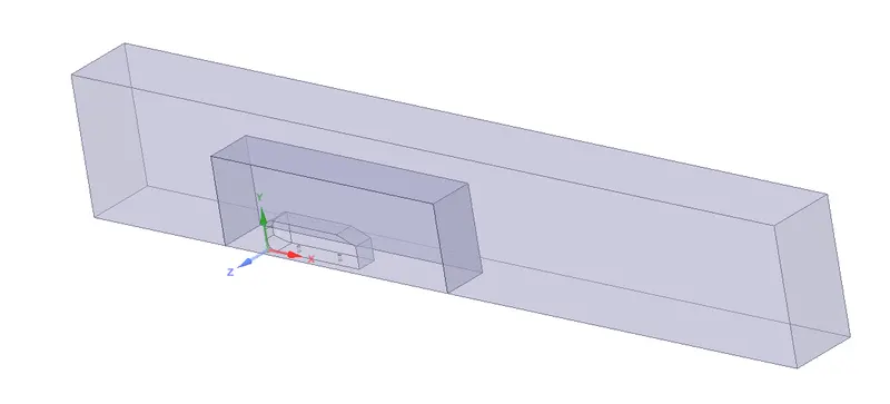
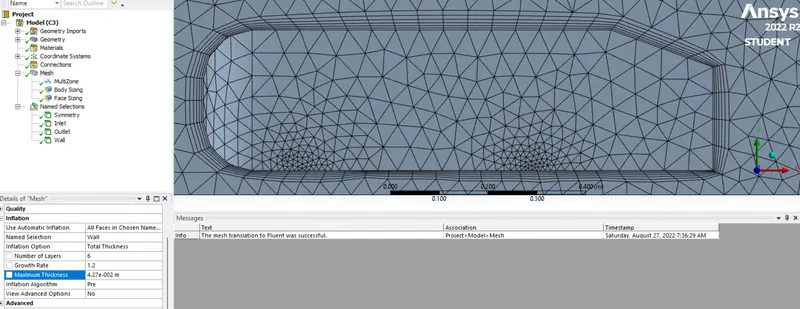
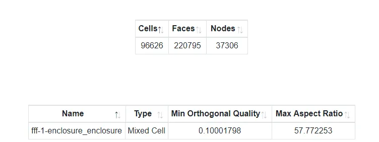
Mesh: Outside enclosure element size is set to 0.08m, Inside Enclosure element size is set to 0.05m, then the Inflation layer is set for total thickness layer to 0.04267m for 6 layers.
Setup:
Reference value:
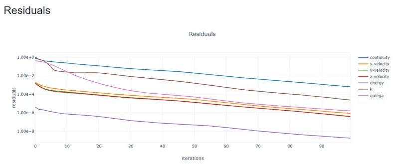
Residual Plot:
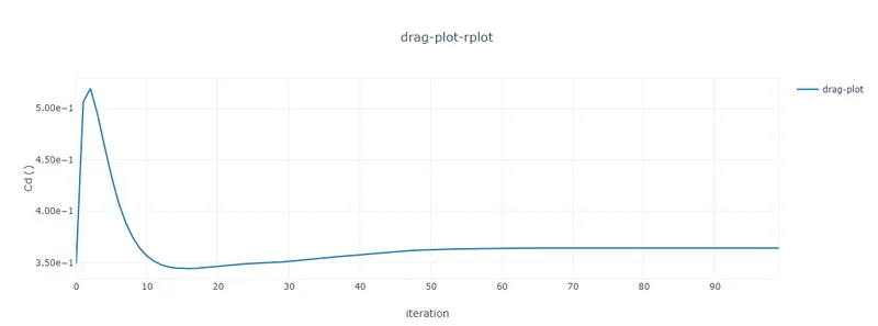
Drag Plot:
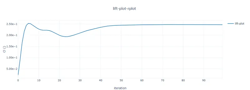
Lift Plot:
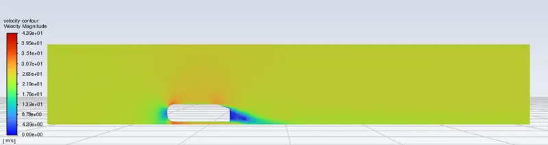
Velocity Contour:
Pressure Contour:
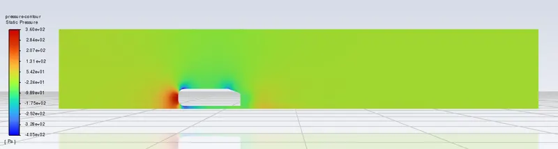
Streamline :
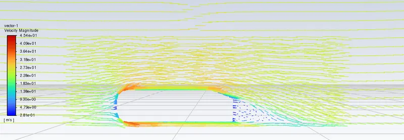
Post Processing:
Velocity Plot at 2m & 3m:
Pressure Plot at 2m & 3m:
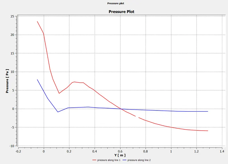
Result_2:
`Simulation for Y+=100`
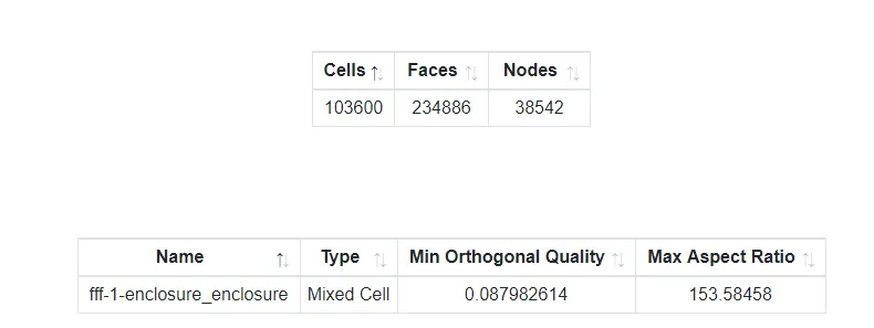
Mesh: Outside enclosure element size is set to 0.08m, Inside Enclosure element size is set to 0.05m, then the Inflation layer is set for total thickness layer to 0.0142m for 6 layers.
Setup:
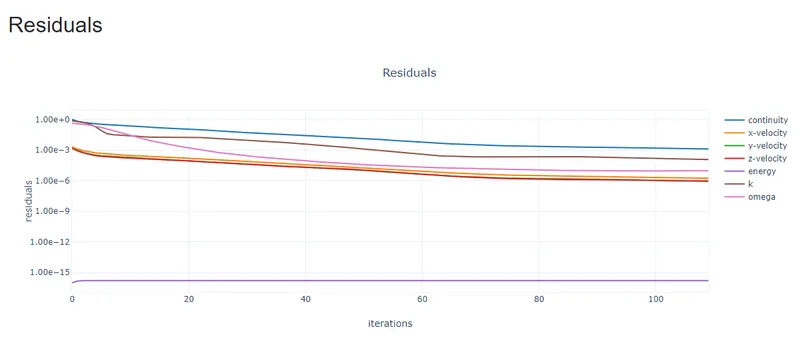
Residual Plot:
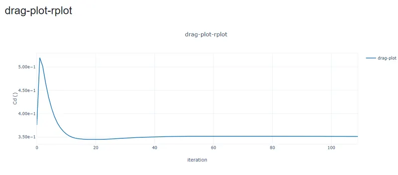
Drag Plot:
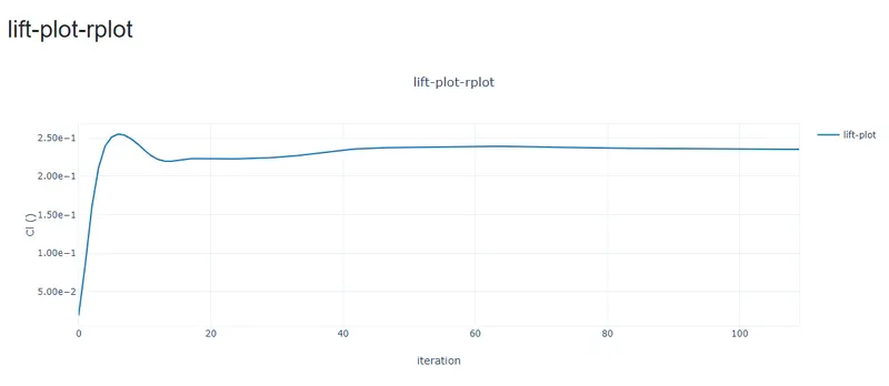
Lift Plot:
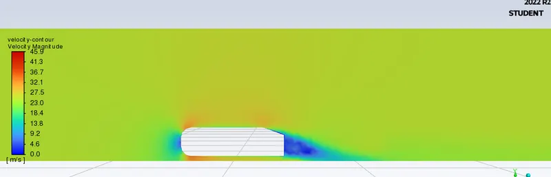
Velocity Contour:
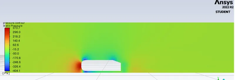
Pressure Contour:
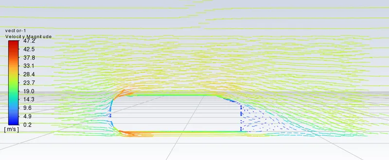
Streamline :
Post Processing:
Velocity Plot at 2m & 3m:
Pressure Plot at 2m & 3m:
Result_3:
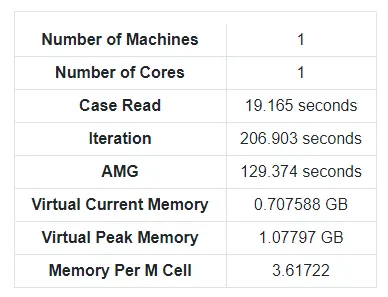
`Simulation for Y+ = 20`
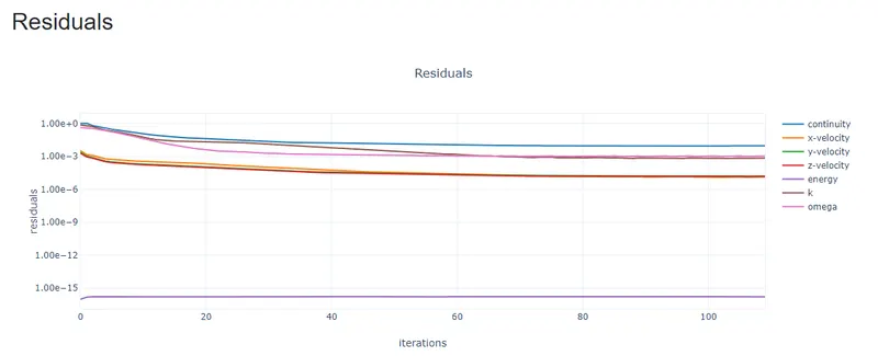
Residual Plot:
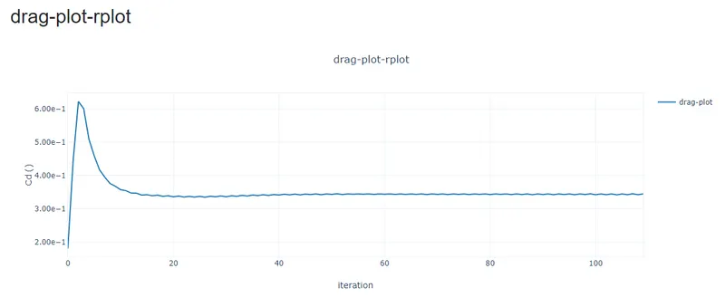
Drag Plot:
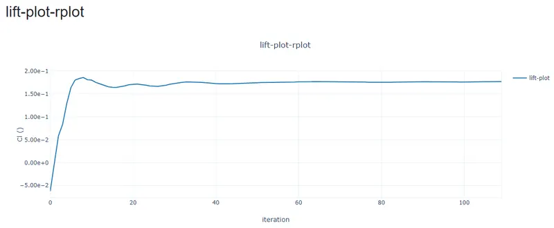
Lift Plot:
Velocity Contour:
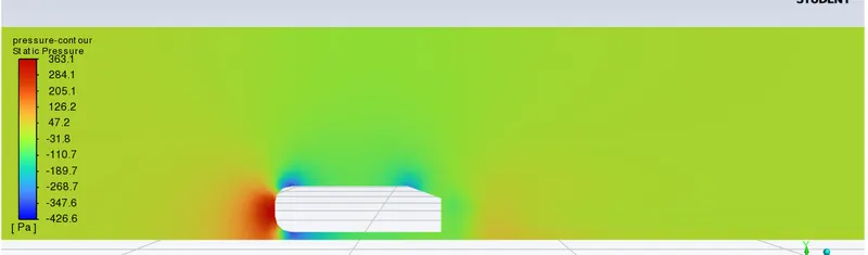
Pressure Contour:
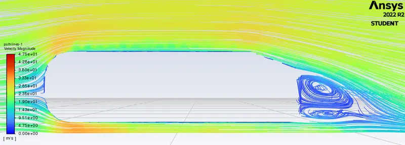
Streamline :
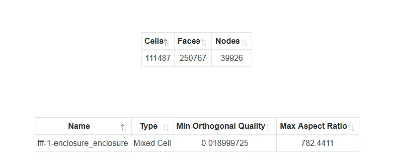
Result_4:
Grid Dependency Test:
|
Y+ |
Element Size |
Inflation (Total Thickness) |
No. of Cells |
No. of Iteration |
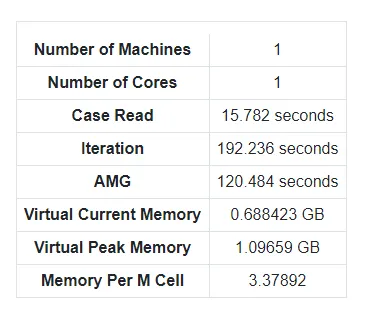
Time in Second |
Coefficient of Lift |
Coefficient of Drag |
Experimental Drag |
% Error |
Turbulence Model |
|
- |
.4m |
- |
84189 |
1000 |
994.228 |
0.248171 |
0.403304 |
0.33 |
22.21 |
K-Epsilon, Realisable |
|
300 |
0.08m |
0.04267m |
96626 |
110 |
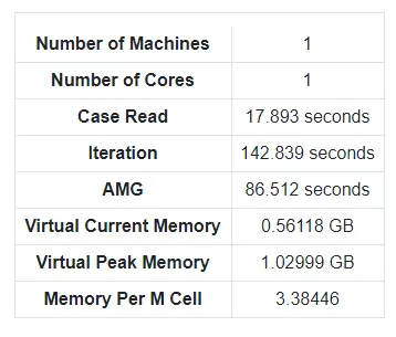
142.839 |
0.246839 |
0.364078 |
0.33 |
10.33 |
K-Omega, SST |
|
100 |
0.08m |
0.0142m |
103600 |
110 |
206.903 |
0.23502 |
0.351322 |
0.33 |
6.45 |
K-Omega, SST |
|
20 |
0.08m |
0.002845m |
111487 |
110 |
192.236 |
0.17728 |
0.34477 |
0.33 |
4.475 |
K-Omega, SST |
- Since the Error obtained are within the limit for Different Grid size, hence the simulation is Grid Independent.
- When we choose the correct Y+ value for the chosen Turbulence model we will tend to get the result more accurate.
Negative Pressure in Wake Region: Wake region plane figure obtained from Y+=20
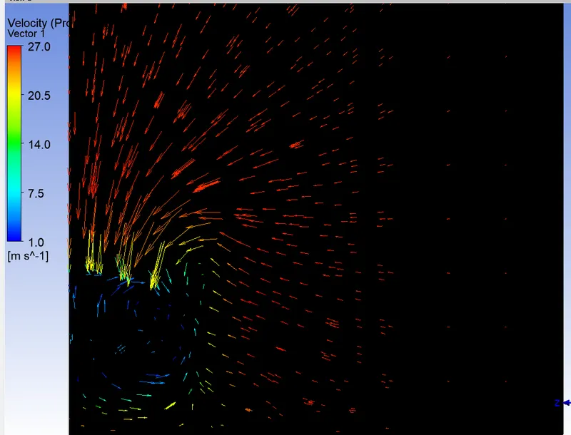
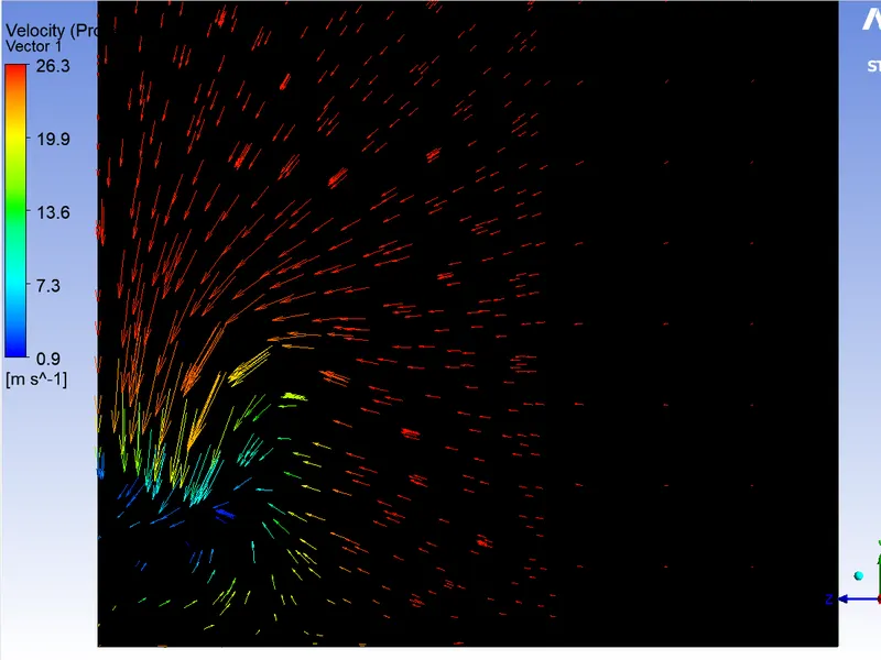
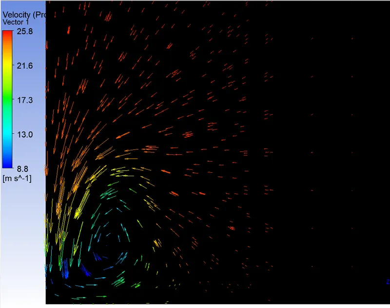
Plane at 1.1m from the origin Plane at 1.2m from the origin Plane at 1.4m from the origin
- When the air moving over the vehicle is separated at the rear end, it leaves a large flow pressure turbulent region behind the vehicle known as the wake. This wake contributes to the formation of the Pressure Drag.
- As the separated flow from the surface enters the recirculating zone it creates low pressure or negative pressure zone and low velocity flow.
- When we try to resolve the flow at the front and rear of the vehicle using Bernoulli’s equation, at the front of the vehicle the velocity is low and pressure is high whereas equating it with the rear we have low pressure, low velocity accompanied by the energy loss due to heat dissipation from the vortices.
- Wake is generated at the rear of the vehicle by the flow from the upper surface and from the side surface causes the counter rotating vortices. While another flow from the lower surface and from the side surface causes another counter rotating vortices.
- The latter counter rotating vortices diminishes under the influence of gravity, so it is important to keep the upper vortices away from the tail of the vehicle to reduce the coefficient of Drag and Lift.
Significance of Point of Separation:
- When there is negative pressure near the surface of the body then the velocity gradient is less than zero i.e. flow reverses its direction this point of flow reversal is know as Point of Separation.
- At the point of Separation wall shear stresses vanishes. Due to flow reversal large and small vortices are formed along the flow known as the Wake.
- Along the flow when the velocity is reduced the pressure starts to rise. So, when the pressure rise is gradual the energy is transferred from large eddies to slower ones. If the pressure rise is rapid like in sharp corners mixing process will be too slow to push air molecules. When this happens, the flow stops to follow the contours of the surface.
- Air particles in the downstream region will move towards the low-pressure region in the reverse direction to the bulk flow. The separation region and will reattach in the region between separation and reattachment points, air flow is circulating and this is called separation bubble.
Result:
- From the Simulation it is clear that vortex generation starts to occur at the back of the Ahmed body, this occurs due to the flow separation.
- If we attempt to reduce wake generation then the Coefficient of Drag value will also reduce, this will directly increase the fuel efficiency of the vehicle.
- Due to this reason Scientist try to make the Vehicle into half tear drop shaped.