Week 3 - External flow simulation over an Ahmed body.
AIM:
- To describe Ahmed's body and its importance.
- To explain the reason for the negative pressure in the wake region.
- To explain the significance of the point of separation.
PROJECT OBJECTIVES:
1. To plot Velocity and pressure contours.
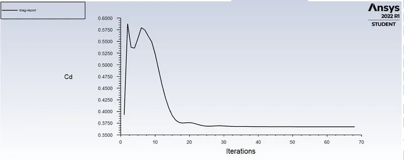
2. To plot the drag coefficient for a refined case. ( For velocity of 25m/sec, the drag coefficient should be around 0.33).
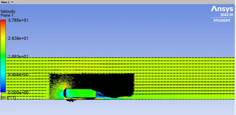
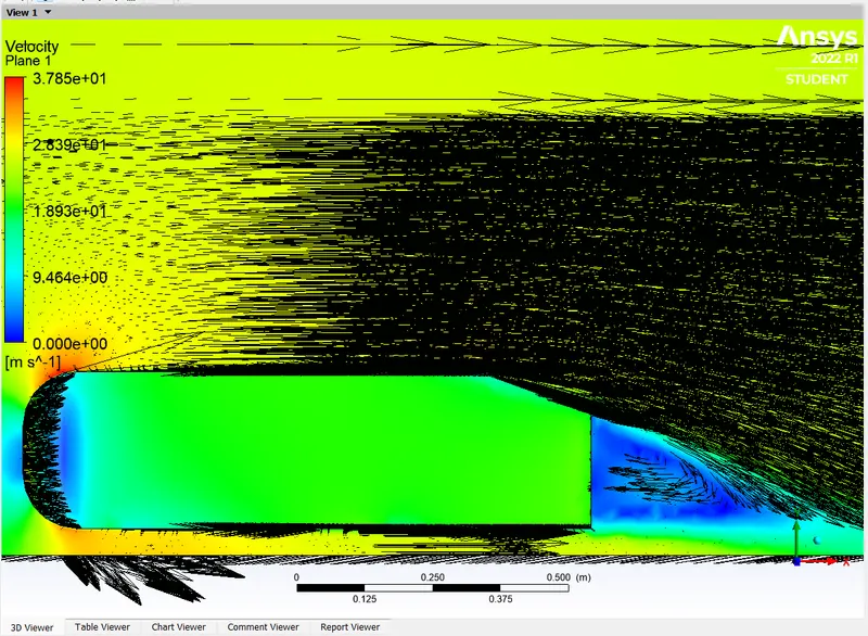
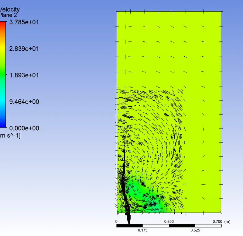
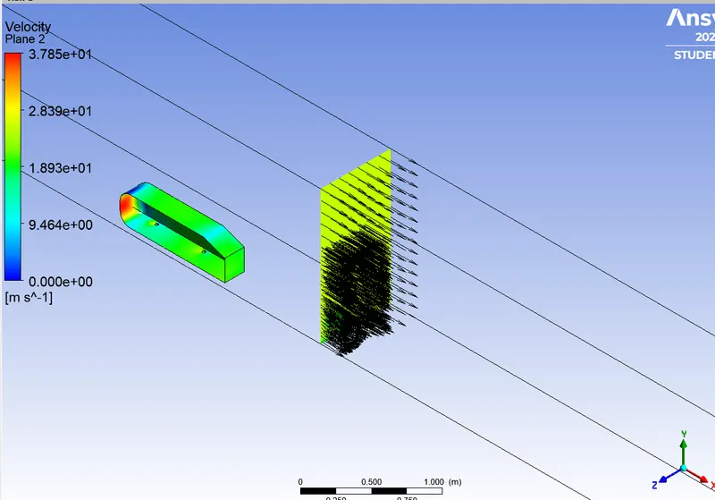
3. To plot the vector clearly showing the wake region.
4. To perform the grid independency test and provide the values of drag and lift with each case.
Ahmed Body:
The flow region which presents the major contribution to a car’s drag and which poses severe problems to numerical predictions and experimental studies as well, is the wake flow behind the car. The location at which the flow separates determines the size of the separation zone and consequently the drag force. Clearly, a more exact simulation of the wake flow and of the separation process are essential for the correctness of drag predictions.
A real-life automobile is a very complex shape to model or to study experimentally. Therefore the MOVA consortium partners (TU Delft, University of Manchester, LSTM, Electricite de France, AVL List, and PSA Peugeot Citroen) agreed to study the vehicle shape employed by Ahmed [1], known as the Ahmed body. Figure 1 is a schematic of the Ahmed body, with actual dimensions in mm included. Two different rear body slant angles (25° and 35°) were considered, which happen to bracket the critical angle of 30° at which separated flow occurs within the wake of the slant.
The particular goal of this benchmark is to compare the Drag Coefficient, Velocity Profiles, Velocity field, and the time-averaged Wake structure of the simulation results with the real experimental measurement in the wind tunnel.
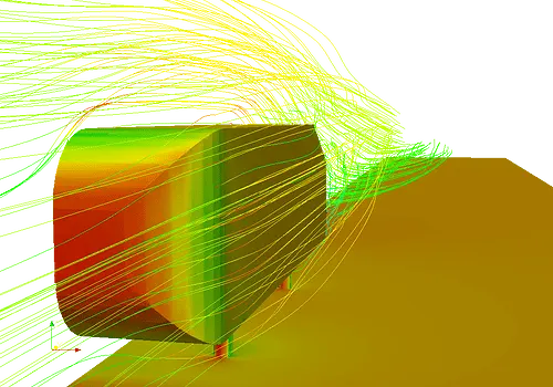
The Ahmed body is a generic car body (a simplified vehicle model). The airflow around the Ahmed body captures the essential flow features around an automobile and was first defined and characterized in the experimental work of Ahmed [1]. Although it has a very simple shape, Ahmed body allows us to capture characteristic features that are relevant to bodies in the automobile industry.
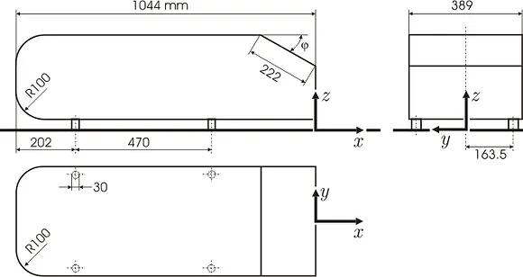
Importance of Ahmed body:
The Ahmed body is a benchmark model widely used in the automotive industry for validating simulation tools. The Ahmed body shape is simple enough to model, while maintaining car-like geometry features.
The total drag coefficient of the Ahmed body is the key measurement for this simulation. It is made up of measurements for the pressure coefficients in the front, slant, and base of the body as well as the body’s skin friction. In the results of the simulation, the total drag is very well predicted but the individual measurements deviate from the experimental results in varying amounts.
Although the data has quantitative differences, it is qualitatively equal to experimental results because the total drag coefficients are so close. There may be deviating details in the smaller data but the simulation still captures the major features of the flow over an Ahmed body. This simulation is more than adequate for calculating the overall drag coefficient.
Negative pressure in the wake region:
The wake is the region of disturbed flow (often turbulent) downstream of a solid body moving through a fluid, caused by the flow of the fluid around the body.
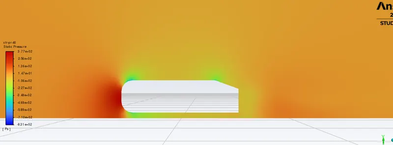
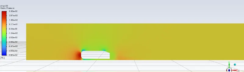
The flow behind an object separates from the surface and creates a highly turbulent region behind the object, called the wake. The pressure inside the wake region remains low as the flow separates and a net pressure force (pressure drag) is produced. In other words, due to the production of pressure drag being produced from flow separation, the pressure in the wake region is low. This is what is causing the vacuum.
The wake particles push the vehicle forward. This effect is minimized on the lead vehicle due to the drag it is producing, however it is beneficial for any cars following closely behind (this concept is called 'drafting'). With drafting, the lead car creates a envelope of less of air behind it, reducing the friction drag for the cars behind it. As the lead car moves it creates a low pressure region, that partial vacuum, behind it which essentially sucks in the car behind it and reduces pressure drag.
Significance of the point of separation:
The separation point is the point where the fluid stops "sticking" to an object that is moving through the air. When an object is moving through the air, the air molecules push back on it and resist the object's movement - this resistance is called pressure drag.
The wake inside the boundary layer is the most important thing to analyze in order to determine the amount of drag (and other forces) experienced by the body.
The flow inside the boundary layer gets detached because of the adverse pressure gradient. This adverse pressure gradient (i.e. flow of fluid inside the boundary layer flowing opposite to the flow of fluid directed over the body because of the motion of the body) then creates a difference in pressure ahead of the body and behind the body which increases the overall drag.
Now from the point of flow separation, inside the boundary layer, the flow gets unsteady and this unsteadiness then propagates as it moves in random fashion (distorted or discontinuous or irregular or turbulent flow). The turbulence then energise the flow closer to the surface, thereby increasing the flow velocity closer to the surface.
PROCEDURE:
Geometry:
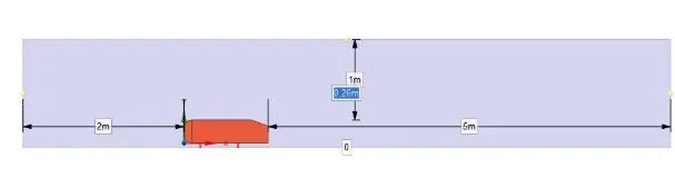
First, open the geometry and import geometry(Ahmed body) in the spaceclaim. The enclosure is made on Ahmed body to analyse the flow pattern and other parameters to be made on discussion.
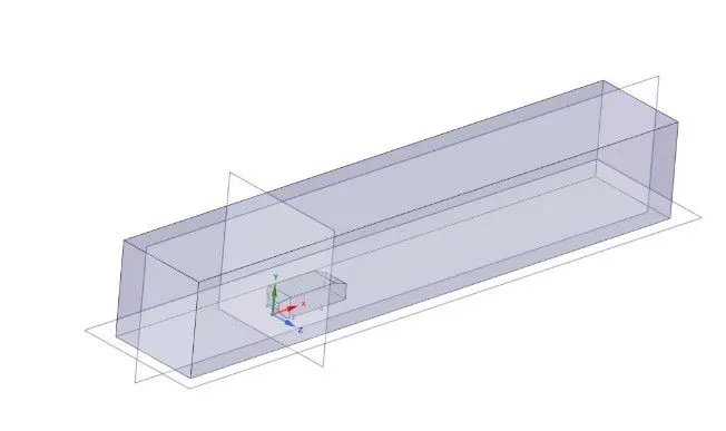
Dimensions for the enclosure:
Then for refinement of mesh near the surface of the Ahmed body, another enclosure is made near the surface of the body.
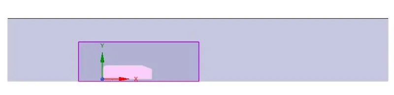
In order to reduce the number of cells in mesh, the body is split into half for easy calculation of the simulation. This is done using 'Split body' option in the tool bar.

Then the body is split into half and the interference check is made using interference tool.

Then the interference portion is removed.
Meshing:
Named selection:
In mesh, first make named selection. Give name to the boundary surfaces.
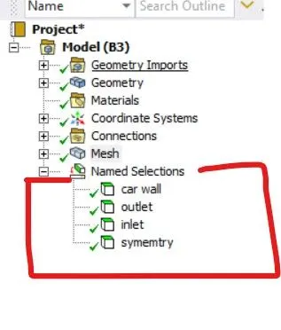
To name the Ahmed body, first hide the outer surface by right clicking it or press F8 shortcut key and select box select tool and name it.
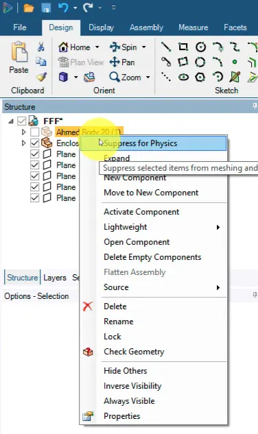
When you section the plane and view the mesh, it is clearly seen that the mesh is created inside the body also where the is no necessity for simulation since the simulation is observed only outside the body surface.
So go to geometry and supress for physics so that simulation is not performed inside the body surface.
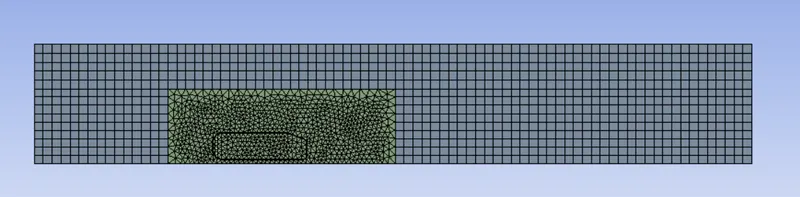
Here we use hexahedral mesh outside the refinement region and inside the refinement region, we use tetramedral mesh.
This is done by right clicking selecting insert ---> Method. Then in the method select "Multizone" after selecting the required body to modify the meshing. All these modifications are done in 'Setup'.
Setup:
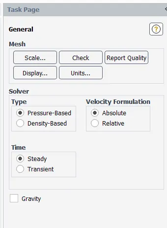
General settings:
Viscous model:
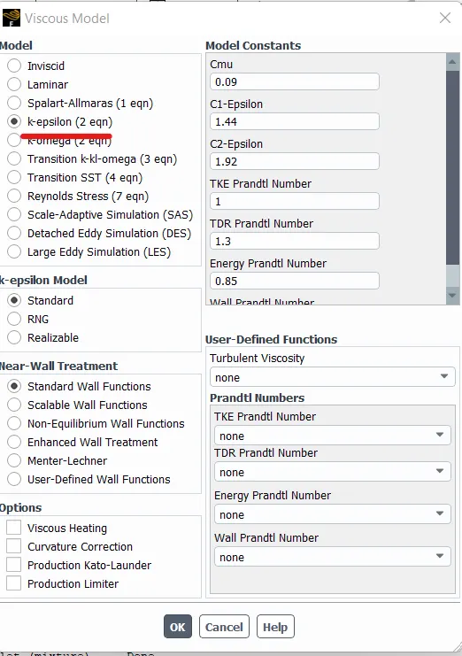
- Energy equation: ON
- Material: Air
- Boundary conditions: Modifiy inlet velocity of air = 25 m/s.
- After modifying all the changes, initialize it. Then go to post processing(Results).
Post processing:
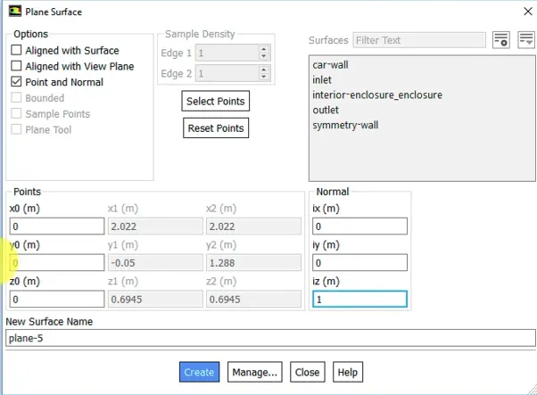
- We need to create a plane along the 'X' axis and normal to the 'Z' axis since the flow is along the 'X' direction.
- Go to 'Create' ---> 'Plane' and select 'point and normal'
- Select point to be origin and normal to be 'z' axis.
Contour plot:
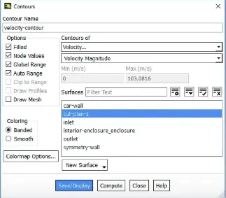
To make a contour plot, go to post processing, select contour. Then select the plane where you need to create the contour and select the variable which the contour plot has to be generated.
Mesh refinement (in Mesh):
In order to make the mesh more refined near the body region, right click the mesh and select 'insert' ---> 'Sizing'.
Now select the body surface needed to be refined and reduce the 'element size' compared to the element size of the outer enclosure. Now generate mesh and have a view of it.
Selecting Inflation:
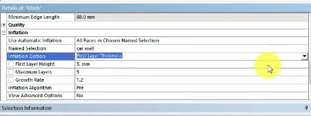
Right click mesh and select method. Open up inflation option and select the body surface in which you need to make the inflation by selecting 'named selection'. Now select the inflation option as 'First layer thickness'. Now select the first layer height as 5mm. The 'total thickness' option can also be provided and we can make the mesh more refinement.
Grid independence test:
To perform grid independency test, make sure that the drag co-efficient for the respective inlet velocity should be close to the obtained simulated value which is done in steps by refining the mesh more to the body closure at each stage.
To make the grid independency test, first go to reference values and change the values of the of the boundary conditions and other parameters that is mentioned and proceed with the simulation.
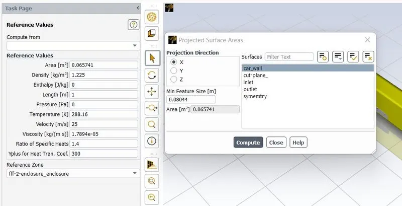
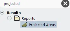
To calculate the projected area, go to results and select projected area and compute the area for the respective body that is desired.
EXPECTED RESULTS:
Grid independence test
Grid sizing for best result:
1. Local refinement mesh size 50:
2. Local refinement mesh size 40:
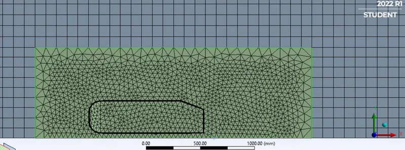
3. Local refinement mesh size 30:
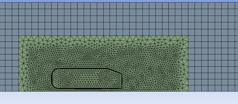
4. Local refinement mesh size 10:
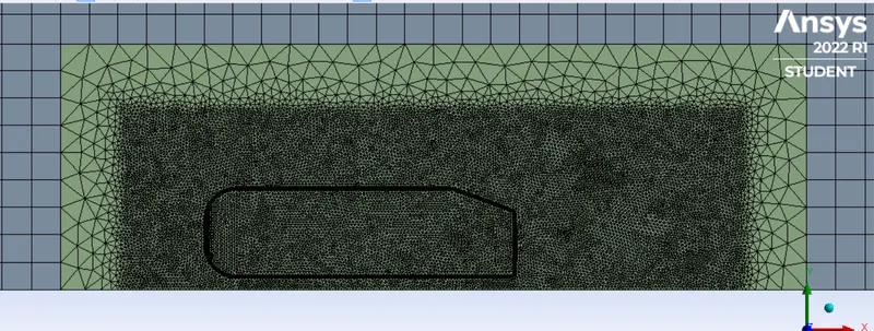
5. Local refinement mesh size 20:
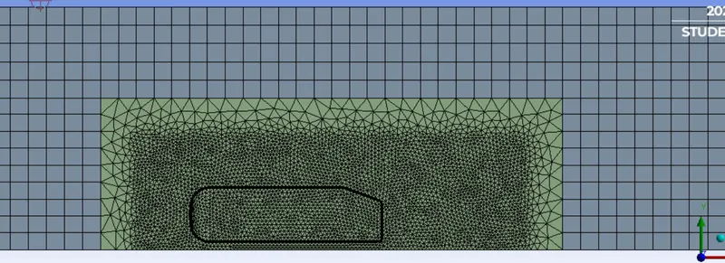
Velocity and pressure contours:
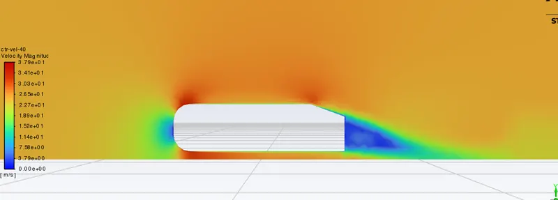
1. Velocity and pressure contour for mesh size 40:
Velocity contour:
Pressure contour:
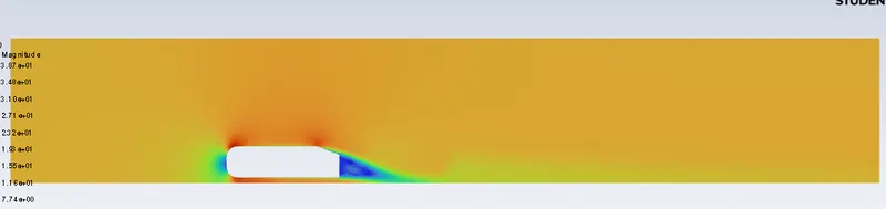
2. Velocity and pressure contour for mesh size 30:
Velocity contour:
Pressure contour:
Drag co-efficient plot for mesh 30(refined case):
Lift co-efficient plot for mesh size 30 (refined case):
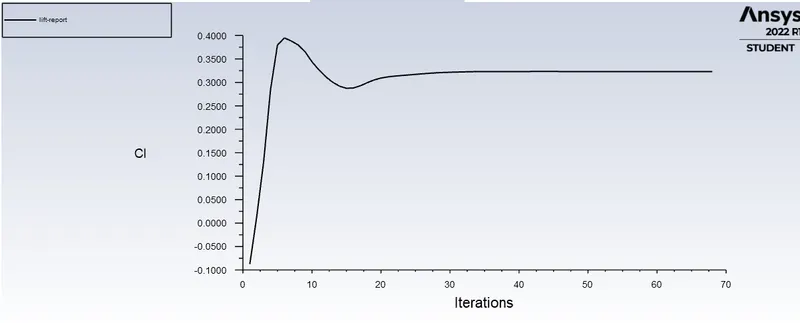
Drag and lift co-efficient for mesh size 40:
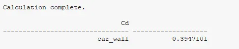

Drag and lift co efficient for mesh size 30


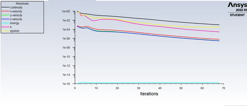
Residuals for refined case (mesh size 40):
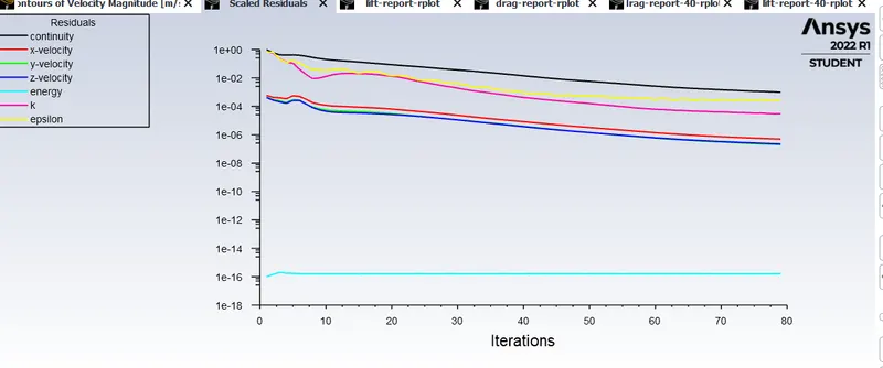
Residuals for refined case (mesh size 30):
The vector plot clearly showing the wake region for refined mesh size 30:
Problems faced:
In order to get the results in more precise manner, mesh size is further reduced to 10mm but the software is limited to student version that could provide results which is 51200 cells only. So mesh refinement is increased to 20mm but still faced the same problem. Thus mesh refinement is limited to 30mm and simulation is proceeded.

CONCLUSION:
Thus all the results are generated and simulation is carried only with the mesh size of 30mm and further could'nt reduce the size of the mesh.