Week 3 - External flow simulation over an Ahmed body.
Aim : External flow simulation over an Ahmed body.
Objective:
Run the simulation for the velocity of 25 m/sec with the default air properties in fluent.
For this challenge, you will have to provide answers to the following questions:
Q1. Describe Ahmed's body and its importance.
Q2. Explain the reason for the negative pressure in the wake region.
Q3. Explain the significance of the point of separation.
Expected Results:
1. Velocity and pressure contours.
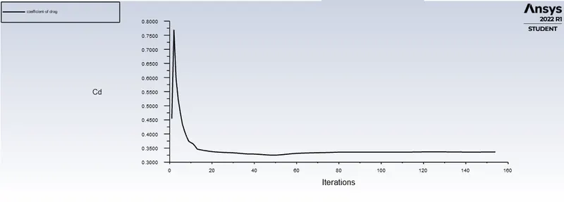
2. The drag coefficient plot for a refined case. ( For velocity of 25m/sec, the drag coefficient should be around 0.33).
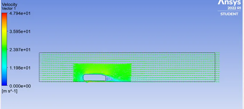
3. The vector plot clearly showing the wake region.
4. Perform the grid independency test and provide the values of drag and lift with each case.
Procedure:
Ahmed body:
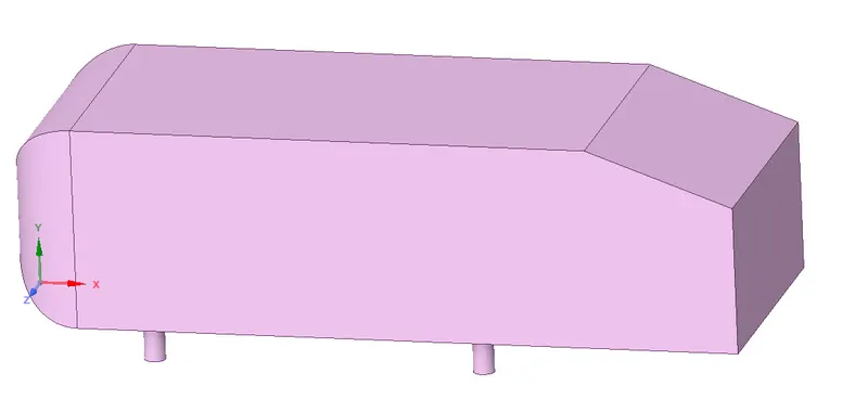
The Ahmed body is a device or 3D model which representative of a standard passenger car ,This model is developed to validate CFD code . The Ahmed body is simplified car body used in automotive field to study the impact of the flow pattern on the drag .The external aerodynamics of the car defines the many major traits of an automobile like stability,comfort and fuel consumption at high speeds.The flow around the vehicle is characterized by high turbulent and three dimensional flow separation as well as there is a growing need for more insight into the physical features of these dynamical flows.The Ahmed body is used in automotive field to investigate the flow analysis and find the wake flow around the body. The Ahmed body is made up of round front part,a movable z slant plane in the rear of the body to study the detachement phenomena at different angles, and a rectangular box which links the front part and the rear slant plane.
Importance of Ahmed body:
The drag force is an important factor considering the fuel consumption.As the drag force is increases the fuel consumption is also increases which in turn becomes expensive for the car owner.The principal objective to study such a simplified car body is to tackle the flow processes involved in drag production.Through perceiving the mechanism involved in creating the drag one can be able to design a car to minimize the drag and therefore reducing the fuel consumption and maximize the vehicle performance.
Why the negative pressure in the wake region?
The negative pressure is due to the velocity difference applied at a certain Reynold number and the rear angle.when the vehicle is moving at a certain velocity the fluid imparts a viscous force to the vehicle as long as it is in the viscous sublayer of the boundary . When the fluid reaches the rear end of the vehicle it get detached from the surface of the body causing the negative pressure in the wake region.The movement of the fluid around the vehicles depends on the geometry of the car and the Reynolds number.
Significance of the point of separation :
The point of separation defined by the Ahmed body and the flow, the alpha angle depending on which value is at it causes the change in flow direction,forces required, lift on the body ,induced drag due to tip vortex ,at a critical value flow in slant stalls and reduced lift reducing as well as drag,all depending on the value of alpha and Reynolds number.
Step 1) Geometry:
- The 3D geometry is shown in figure below
- Create the 1st outer enclosure for the Ahmed body because we have to simulate the external flow.
- The right side face distance from the Ahmed body is 5m, left side face distance is taken as 2m from the Ahmed body .
- The top side face distance from the Ahmed body is 1m along Y axis .
- The bottom face of the enclosure is attached to the bottom face of the Ahmed body.
- The front and back face of the enclosure is at a distance of 0.5m along z axis
- Create the Inner enclosure :
- Right face is located at distance of 1m from the right side face of Ahmed body along x axis.
- Left face is located at distance of 0.5m from the left side face of Ahmed body along x axis.
- Top face of the enclosure is at a distance of 0.5m from the top side face of the Ahmed body along the Y axis.
- The bottom face of the enclosure is attached to the bottom face of the Ahmed body.
- The front and back face of the enclosure is at a distance of 0.26m along z axis
Both the enclosure with Ahmed body:
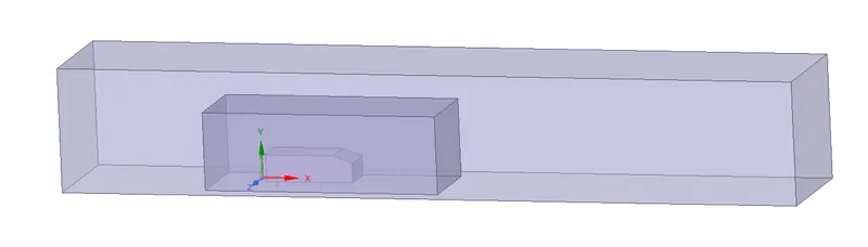
- There is a interference due to both the enclosure due to that the mesh is get overlapped in order to avoid that we use interference command and remove this interference.
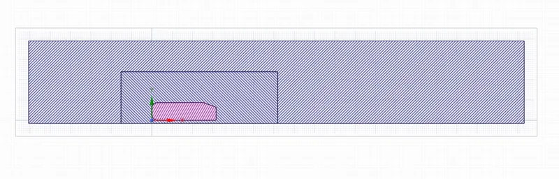
- The geometry is symmetric along x axis so we use split body command and split the body along X axis
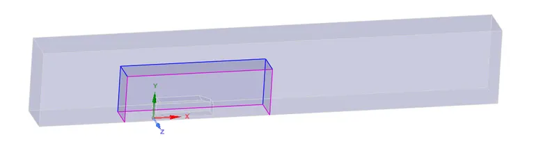
Step 2) Mesh :
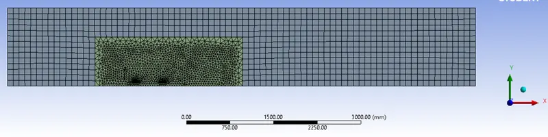
The Ahmed body is surrounded by a very fine hexahedral grid to capture the flow structure and inner enclosure is surrounded by tetrahedral grid and inflation layer is created over the Ahmed body wall to capture the flow separation from its rear.
Case 1)
Simulation was done for total number of mesh counts =98123.
Outer enclosure domain =100mm size of Hexahedral mesh.
Inside enclosure domain= 50mm size of Tetrahedral mesh
and 5 inflation layer around the wall of Ahmed body with Maximum thickness =1.7826 mm. I am using Y+ value is 50 to capture the turbulent boundary layer near the wall .
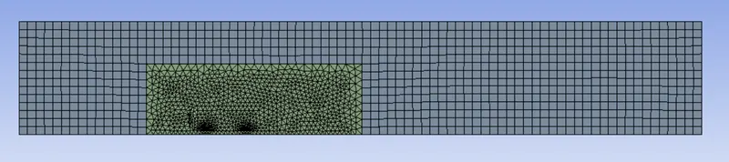
Mesh quality:
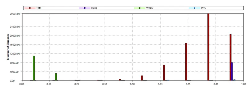
The elemental quality of mesh is checked and observed the quality is more than 40%
Step 3)Set up and solution : Solver set up
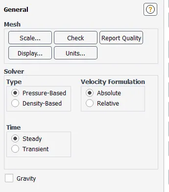
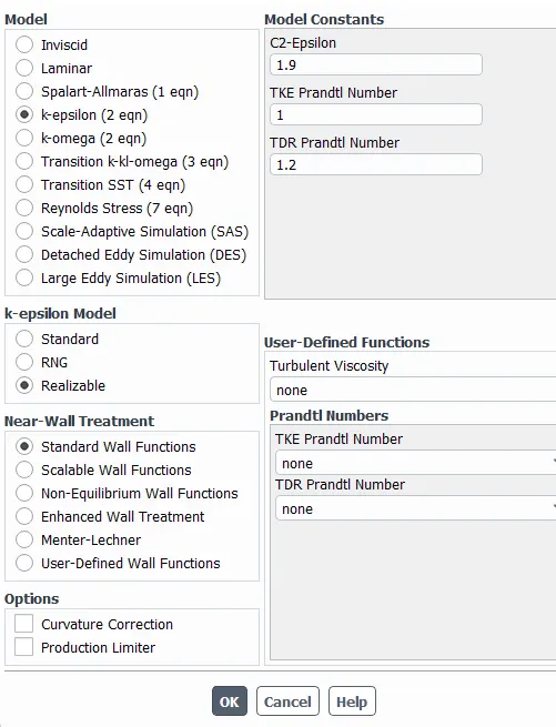
Viscous model:
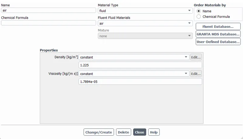
Material properties
Boundary condition :
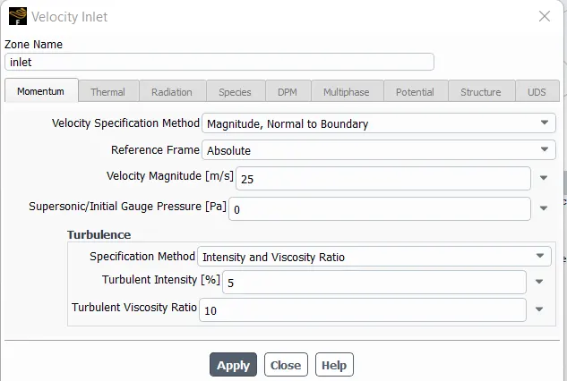
Inlet:
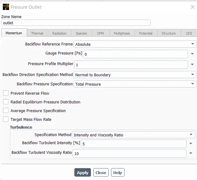
Outlet:
car-wall Type=wall
symmetry-wall Type= symmetry
Reference value setting for calculating Drag coefficient:
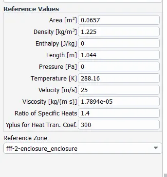
The reports plots for Coefficient of Drag and Coefficient of lift is created in solution .
The Hybrid initialization is used.
Results setting :Create plane for contour plots :
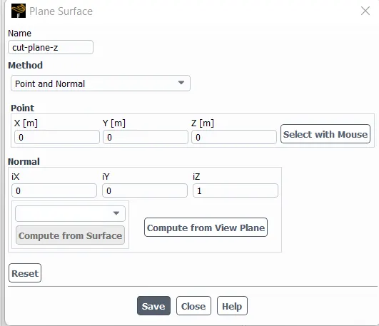
This plane selected for pressure and velocity contour plot
Step 4) Results:
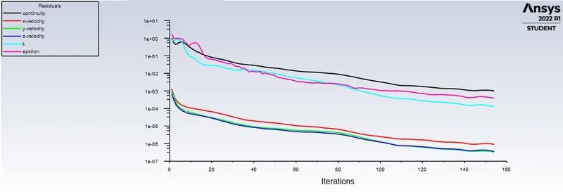
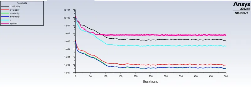
1) Residual plot:
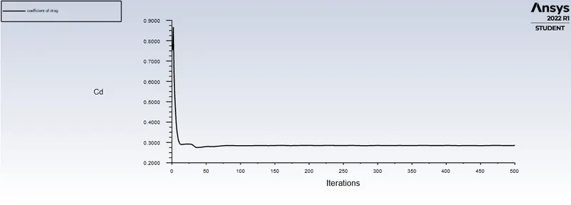
2) Coefficient of Drag plot:
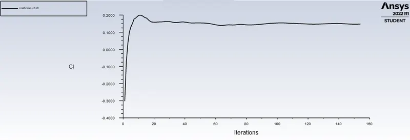
3) Coefficient of lift plot:
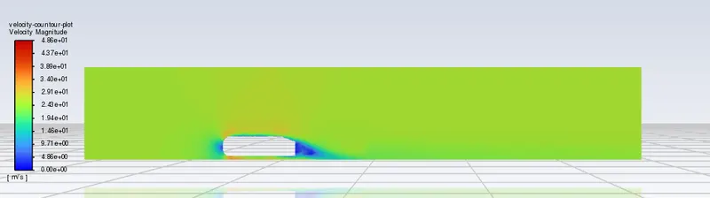
4)Velocity Contour plot:
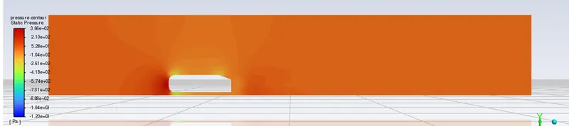
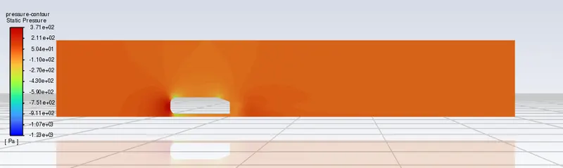
5) Pressure Contour plot:
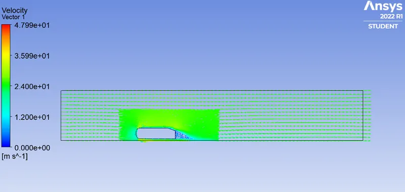
6) Velocity vector plot:
Case 2)
Simulation was done for total number of mesh counts =146430.
Outer enclosure domain =100mm size of Hexahedral mesh.
Inside enclosure domain= 40mm size of Tetrahedral mesh
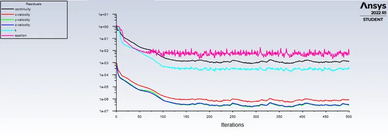
Residual plot:
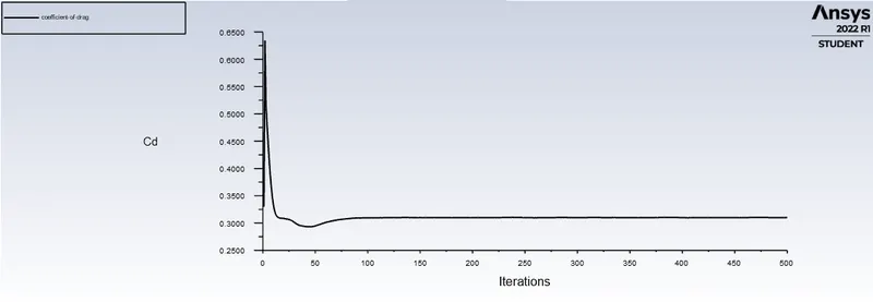
Coefficient of Drag plot:
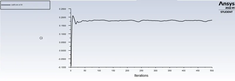
Coefficient of lift plot:
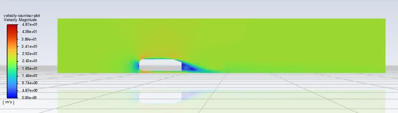
Velocity Contour plot:
Pressure Contour plot:
Velocity Vector plot:
Case 3)
Simulation was done for total number of mesh counts =274369.
Outer enclosure domain =100mm size of Hexahedral mesh.
Inside enclosure domain= 30mm size of Tetrahedral mesh

Residual Plot:
Coefficient of Drag plot:
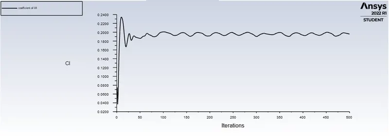
Coefficient of lift plot :
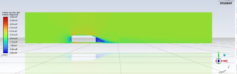
Velocity Contour plot:
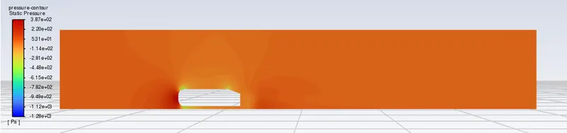
Pressure contour plot:
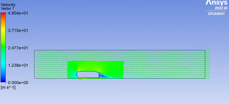
Velocity vector plot:
Grid Independent Test:
| Sr No | No of Elements | Coefficient of Drag | Coefficient of lift |
| 1 | 98123 | 0.3359 | 0.1473 |
| 2 | 146430 | 0.3098 | 0.1811 |
| 3 | 274369 | 0.2849 | 0.1957 |
Conclusion :
- The base line mesh give poor result it was not able to capture the flow around the Ahmed body and the wake structure.due to coarse mesh .
- The refine mesh gave better results. The results plot shows the wake formation accurately and flow around the Ahmed body is also captured very well.
- There is a pressure variation around the Ahmed body .The presssure in front of the Ahmed body is positive because that is face at which flow comes in contact with the body come to rest ,At the corner of body the flow accelerates and decreasing the pressure .
- The negative pressure behind the Ahmed body is due to flow separation,recirculation flow and that is the wake region.
- The point of separation occure at the rear end of teh Ahmed body ,the separation occurs beyond this points where it can be observed that the flow recirculates and attaches it to the boundary layer.