Week 3 - External flow simulation over an Ahmed body.
Aim
To perform an External flow simulation over an Ahmed body.
Introduction
Ahmed body
The generic Ahmed Body reference model has been chosen as the benchmark for carrying out computations for studying of the aerodynamic parameters. The body was first proposed by Ahmed et al., (1984). The Ahmed body is a very simple bluff body which has its shape simple enough to allow for accurate flow simulation but retains some important practical features relevant to automobile bodies. It has a slant on its rear end, whose angle can be manipulated and the corresponding drag and lift coefficients calculated. This is done to exhibit the air flow over the different geometry sections of an automobile and in its vicinity, at different slant angles.
Importance
The pollution emerged by using volatile fuels in automobile has become a major concern pertaining to the environment and economic viability. Different approaches such as improving the efficiency or usage of alternative fuels for the vehicle have been considered. Advancement in some of the major areas such as aerodynamics improvement, weight reduction and power increase has given us many feasible results, but reducing aerodynamic factors such as drag, lift is more efficient than increasing the power of the vehicle or decreasing the weight of the vehicle. Automotive aerodynamics comprises of the study of aerodynamics of road vehicles. Its main goals are reducing drag, minimizing noise emission, improving fuel economy, preventing undesired lift forces and minimising other causes of aerodynamic instability at high speeds. Also, in order to maintain better control for steering and braking, we look into design and aerodynamics of a vehicle. Drag is caused due to the pressure difference between the frontal and the rear end of the vehicle. It can be reduced by modification of the design of the vehicle or the modification of the air flow around the vehicle. 50% of the mechanical energy of the vehicle is wasted to overcome drag at highway speed of nearly 88.5 to 96.5 kph. It is necessary, at times, to generate down force - to improve traction and thus cornering abilities. Lift can be dangerous for an automobile, especially at high speeds. So, in order to maintain control for steering and braking, cars are designed so that the automobile exerts a downward force as their speed increases. However, increasing this downward force increases drag, which in turn, limits the top speed and increases fuel consumption. Hence, these two forces must be carefully balanced. Air has a tendency to curl downwards around the ends of a car, travelling upwards from the highpressure region under the car to the low-pressure region on top, at the rear end of the automobile and subsequently collides with moving low-pressure air. The kinetic energy of these turbulent air spirals acts in a direction that is negative relative to the direction of travel intended. Thus, the car engine must compensate for the losses created by this drag. Vortices are released during flow separation and trail downstream to form structured or unstructured wake patterns. A wake is the region of re-circulating flow immediately behind a moving or stationary solid body, caused by the flow of surrounding fluid around the body. The local disturbances in the flow pattern behind the vehicle causes a momentum loss thus causing form drag which extends far behind the bodyworks of a vehicle.
angles
Geometry
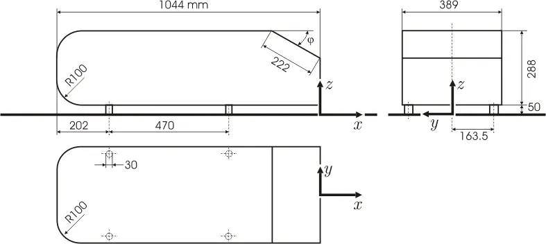
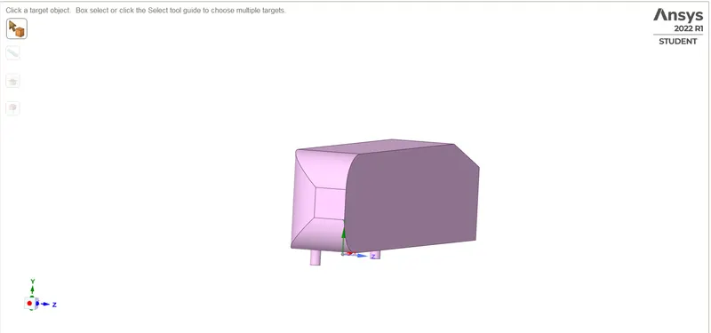
The above geometry is split since it is symmetrical and is used to reduce the number of results using the split command.
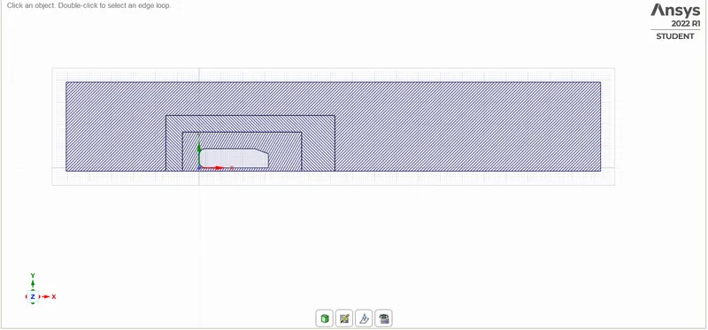
The initial geometry is imported from other design softwares and using the plane and split command, it is cut in half. Then using the enclosure and interference command the boundary layer is set and depending on the base vague region additional layers are set as per the wind tunnel.
Meshing
The inlet, outlet, symmetry and the car-wall are named.
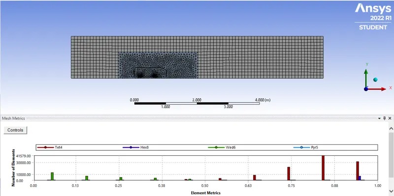
Since the outer layer is mostly a box, the hexagon mesh is selected for it with a base mesh size of 0.1m and max size of 0.1m.
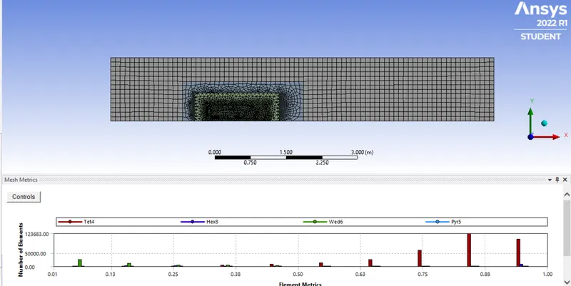
Then the second layer mesh is reduced to 0.05m.
The mesh for the bottom of the ahmed body will be reduced to 0.005m to get the proper shape of it.
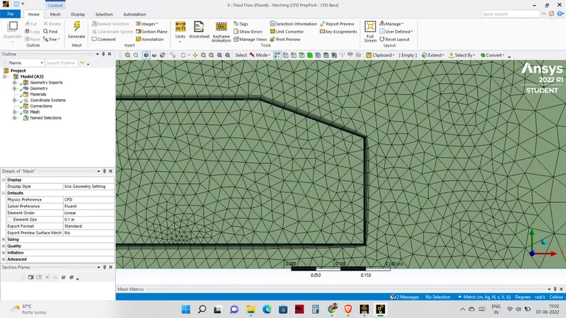
It's important that the mesh near the wall is properly sized to ensure accurate simulation of the flowfield. Therefore considering the y+ value as one and the freestream velocity as 25m/s the element sizing is calculated for the inflation layer. The initial spacing is 0.42 and 10 layers are selected.
The total number of elements here are 385808.
Set-up
The phsyical are set up
Inlet -25m/s
Outlet - 1atm
Symmetry-wall - symmetry
Wall - car-wall
The reference values are set to area of 0.065741 and length of 0.94 and velocity of 25m/s.
since the mach number is less than 0.3 Pressure-based solver is used, with absolute formulation, and steady state condition to get the drag and lift co effiecients.
A plane normal to the X axis is created to project the velocity and pressure contours.
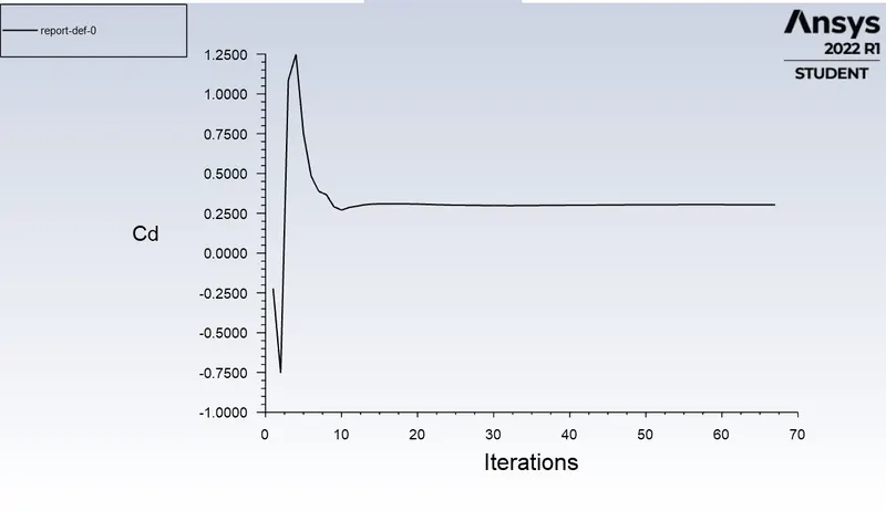
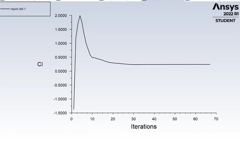
Then using the definitions-force report-darg option, the drag and the lift are plotted.
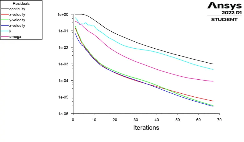
Residuals
Drag coefficient
Lift oefficient
Animation
https://www.youtube.com/watch?v=DOCIgOS8Sa4
CFD post
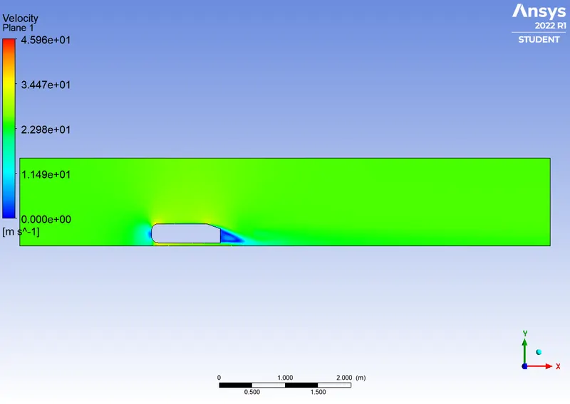
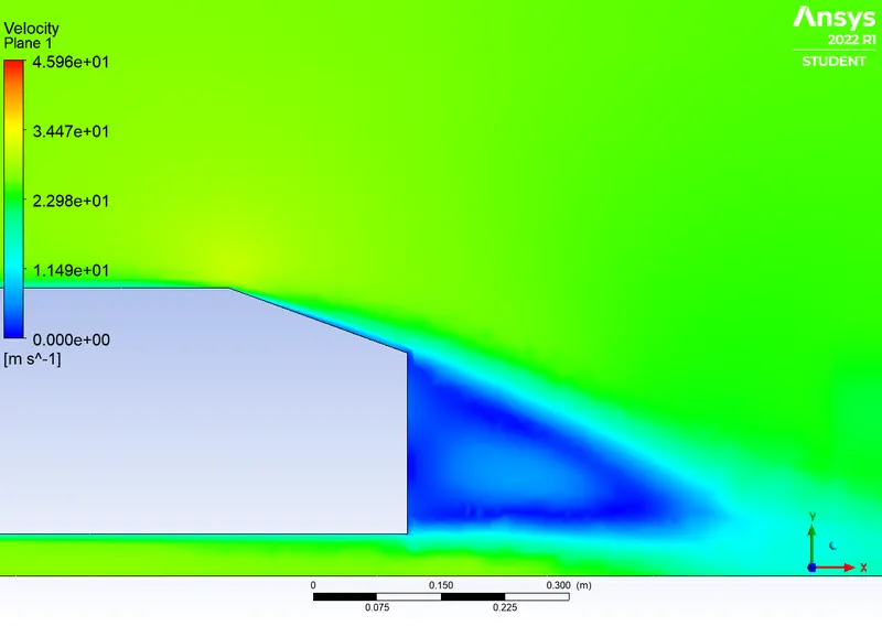
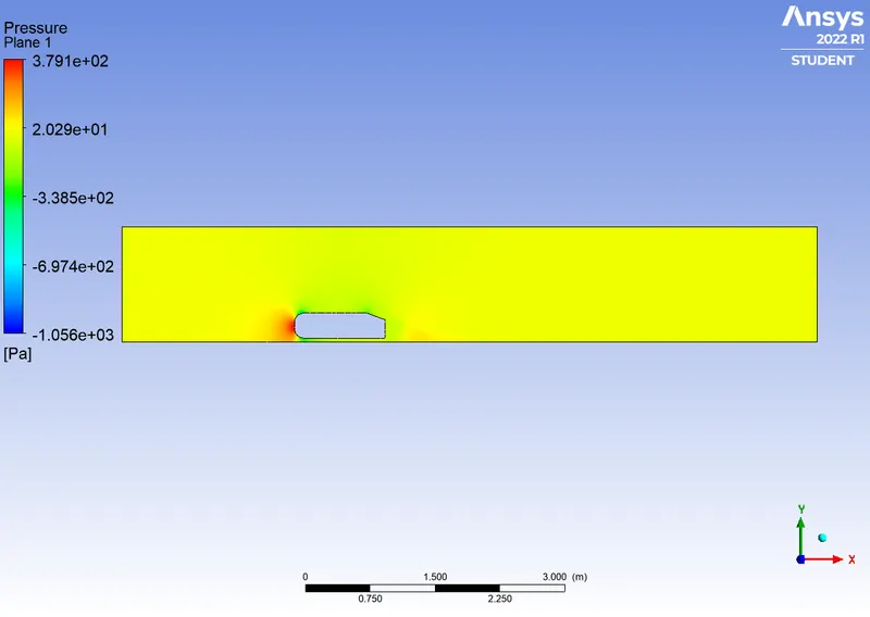
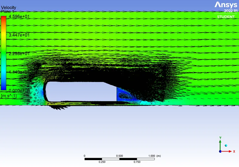
To get the velocity and pressure contour a plane is created along XY axis and changing the variable to either pressure and velocity we can get the result.
Velocity
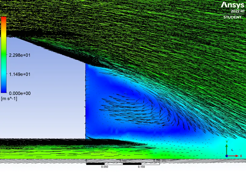
Velocity at Wake region
Pressure
Pressure at Wake region
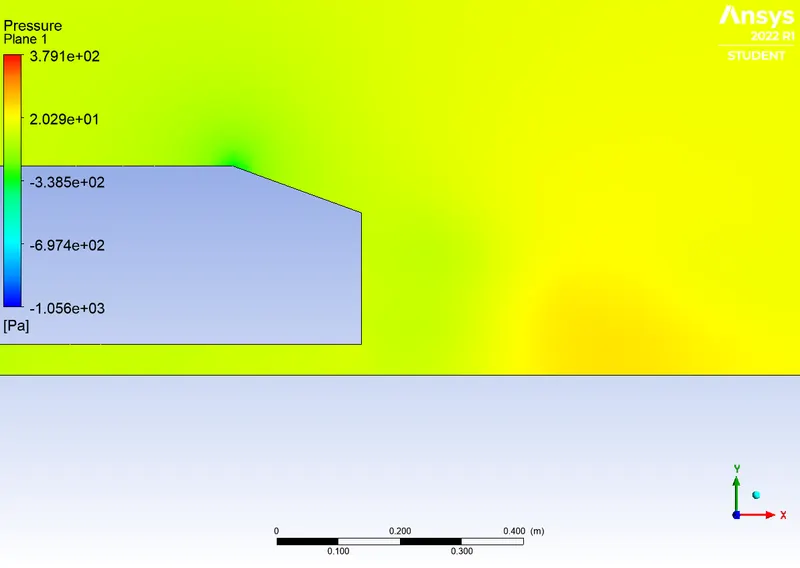
The reason for the negative pressure in the wake region.
When the air moving over a vehicle is separated at the rear end, it leaves a large low pressure turbulent region behind the vehicle known as the wake. This wake contributes to the formation of pressure drag, which is eventually reduces the vehicle performance. This is the reason for negative pressure in the wake reagion.
The significance of the point of separation
The separation point is the point where the air stops "sticking" to an object that is moving through the air. When an object is moving through the air, the air molecules push back on it and resist the object's movement - this resistance is called pressure drag. As the air flows around the object, it "sticks" to the object, forming what is known as the boundary layer. This "attached flow" is flowing very smoothly. The point on the body where the boundary layer lifts off the surface is called the separation point. When the air flow separates off the surface, the pressure drag usually increases. Therefore point of separation plays a vital role in the drag and lift coefficient
Vector plot
Vector plot at the Wake region
Grid Independence test
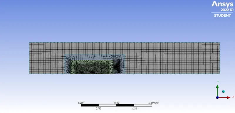
Coarse mesh
Same mesh for the first layer but the second layer mesh was increased to the size of the first layer 0.1m as well as the third layer mesh was increased from 0.25m to 0.3m
Base mesh
In this case only one layer is added and the grid size for it was set to 0.05m and everything else is the same from the first case.
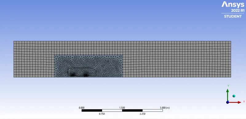
The grid dependency test allows us to see smoother velocity profile. As we make the mesh finer i.e. when we increase the cell counts (closer to the limit), we can see from the vector plots from all the 3 cases, of the velocity that it becomes more and more smoother. One thing is observable that making the mesh finer lets us see the wake region more prominent. From the 3 cases, we can conclude that the flow is more defined at lower element size i.e. at case 1. The finer the mesh gets, the easier it gets in visualizing the contours. Mesh refinement increases the closeness of the resulting values to the true values. From above observations, we conclude that Grid is independent but there is some margin of error which can be caused by a number of other simulation parameters, for example, the turbulence model chosen for this simulation is not the best one for it. Local refinement of the enclosure is a great tool for performing analysis and it improved the results without which wouldn’t have been so accurate and cleared grid dependency in fluent. This study for all practical purposes gives a great real-world scenario of aerodynamic impact on a car body, which when improved can help overcome many challenges faced by automobile.
Results
| Mesh type | No of elements | Lift coefficient | Drag coefficient |
| Fine | 385808 |
2.5556e-01 |
3.0386e-01 |
| Coarse | 242771 |
2.4369e-01 |
3.1289e-01 |
| Base mesh | 140339 | 2.2219e-01 |
3.5159e-01 |
As the number of elements increases drag coefficient decreases and lift coefficient increases slightly.
Therefore it can be concluded that as mesh number is increases, we get accurate results.
Conclusion
Thus the simulation and analysis of external flow over an ahmed body for both the cases has been done.
References
https://asset-pdf.scinapse.io/prod/2273955811/2273955811.pdf