Week 3 - External flow simulation over an Ahmed body.
Aim:
To run the simulation on Ahmed body for the velocity of 25 m/sec with the default air properties in fluent.
Objectives:
1.Describe Ahmed's body and its importance.
2.Explain the reason for the negative pressure in the wake region.
3. Explain the significance of the point of separation.
Introduction :
Ahmed Body:
The Ahmed body is a generic car body (a simplified vehicle model). Although it has a very simple shape, Ahmed body allows us to capture characteristic features that are relevant to bodies in the automobile industry.It is used in automobile industry to study the impact of the flow pattern on the drag. The external aerodynamics of the car defines the major traits of an automobile like stability, comfort and fuel consumption at high speeds. The flow around the vehicle is characterised by high turbulent and 3 dimensional flow separations as well as there is a growing need for more insight into physical features of this dynamical flows. Ahmed body it's made up of round front part, a moveable z slant in the rear of the body to study the detachment phenomena at different angles, rectangular box which link the front part and the rear slant plane. The principal objective to study such as simplified car body is to tackle the flow process involved in drag production.
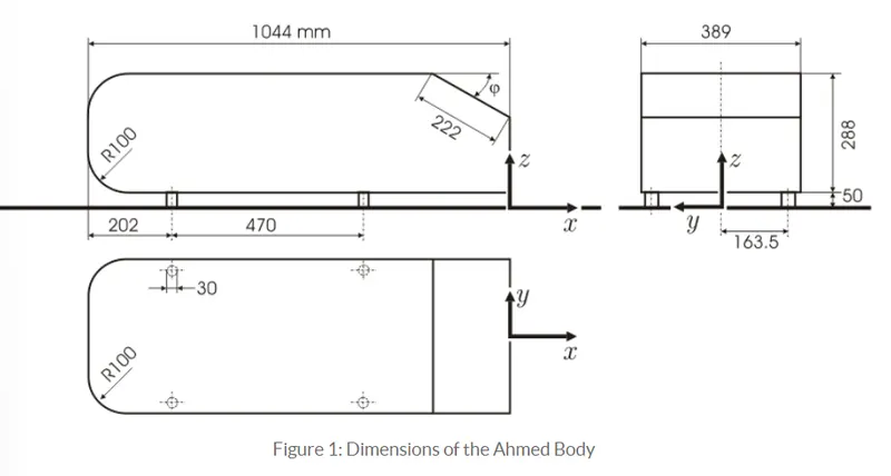
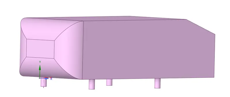
Geometry setup:
As the body is perfectly symmetric, we can run the simulation by considering of the body. So so by this way we can decrease the number of cells used in the simulation and could get the results way faster. The geometry provided with a challenge need a small modification we should use the split body command to split the Ahmed body in the space claim and use the symmetry boundary condition in the fluid to perform the simulation.
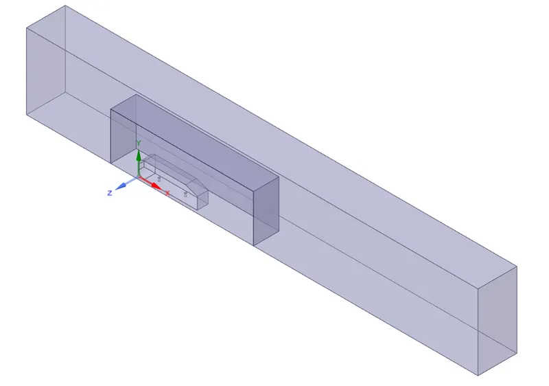
At first to load the Ahmed body step file into the space claim and convert the units from millimetres to metres. Now go to prepare and click on the enclosure and select the Ahmed body. Enter the enclosure dimensions and uncheck the symmetry condition and click ok.
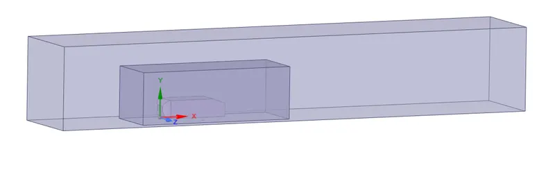
Once the inner and outer enclosure is created. We can check interference and avoid overlapping of meshing on the enclosures by applying check interference undeleting the overlap. This is automatically done by spaceclaim when the interference option is selected inside prepare
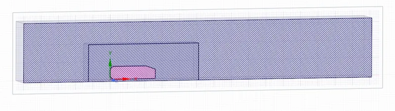
Now we can use the split body option 2 split the body into 2 equal parts and delete theother symmetrical part. This can be done by using the split body option in the design , select the body and plane to be acted as cutter and select the body to be removed follow the steps for the other enclosure and ahmed body.
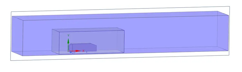
After achieving the split, hide the ahmed body, suppress the physics and close the spaceclaim geometry and go to mesh.
Mesh setup:
Open the mesh from the module and select mesh and generate a simplified mesh.Create named selection by selecting the faces of the geometry and specify names like inlet, outlet, symmetry, carwall.
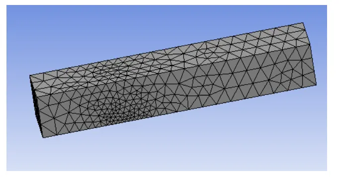
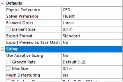
Now right click mesh and select method and select the body and select multi zone show the hexa elements are created on the body an inside mesh select the elements as as 100 mm and in sizing select the maximum size 100 mm.
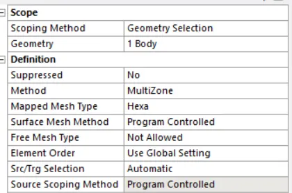
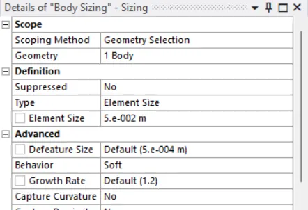
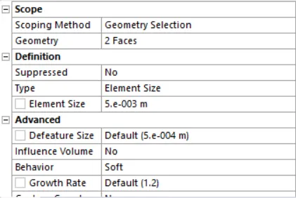
Right click mesh and select sizing and select the second enclosure and select the element size as 50 mm.Again right click the mesh and select sizing and select the bottom pillars of the Ahmed body faces and specify the elements as 5 mm.
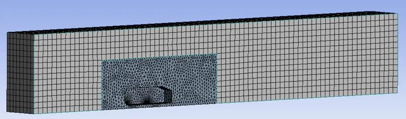
Under mesh select inflation and select all faces chosen in name selection and select total thickness and specify the number of layers required and and calculate and specify the maximum thickness.
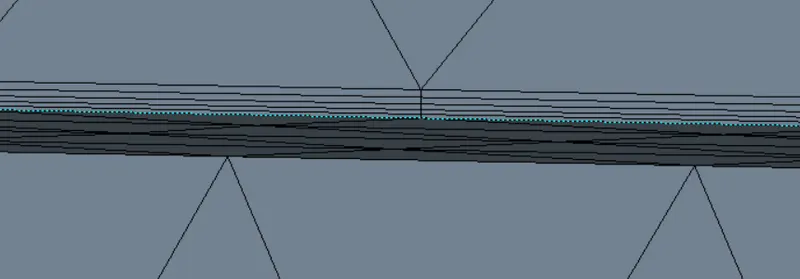
Total Thickness calculation:
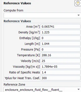
`Re=(rho * v * L)/mu`= (1.225 *25*1.044)/1.7894e^-5 = 1786772.10
`C_f=0.026/(Re^(1/7)`= 0.026/(1786772.1)^0.14825714 = 0.003076
`T_w=(c_f*rho*v^2)/2` = (0.003076 * 1.25 * 25*25)/2 = 1.1775
`mu_f=sqrt(T_w/rho)`= `sqrt(1.1775/1.225)`=0.98042
`Y=y^+*mu/(mu_f*rho)`=100*1.7894e^-5/(0.098042*1.225) = 0.0014899
Total Thickness = `Y*[1.2^(Num.of layers-1)]`=0.00300894
The Fluent setup:
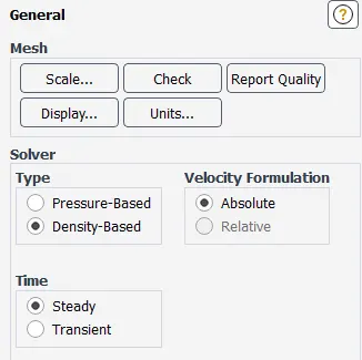
1.Select the density based solver and choose k- epsilon method .
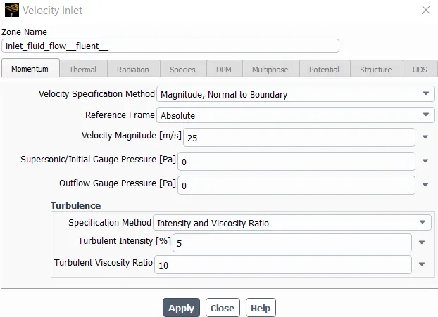
2.Select the boundary conditions and specify the values.
3.Set the reference values in the genral section.
4.Select the hybrid initialisation and initialize the simulation.
5.Then create a cut plane on the model and select the velocity contour and create report definitions for coefficient of drag and lift.
6. Run the simulation.
Case 1:
Outer enclosure : 100mm
Inner enclosure : 50 mm
Face sizing for ahmed body : 5 mm
Inflation for ahmed body - Total thickness : 3.0894mm
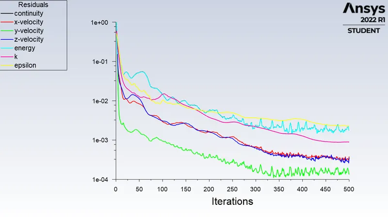
Residuals:
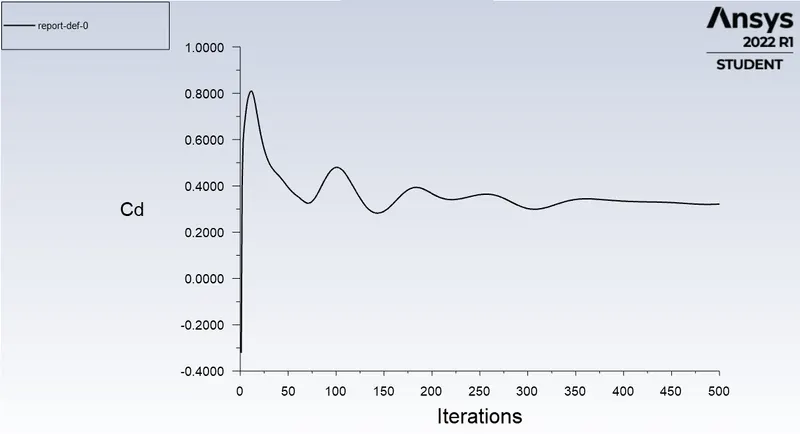
Coefficient of drag:
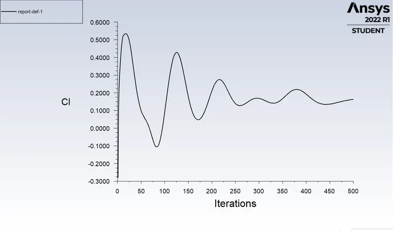
Coefficient of Lift:
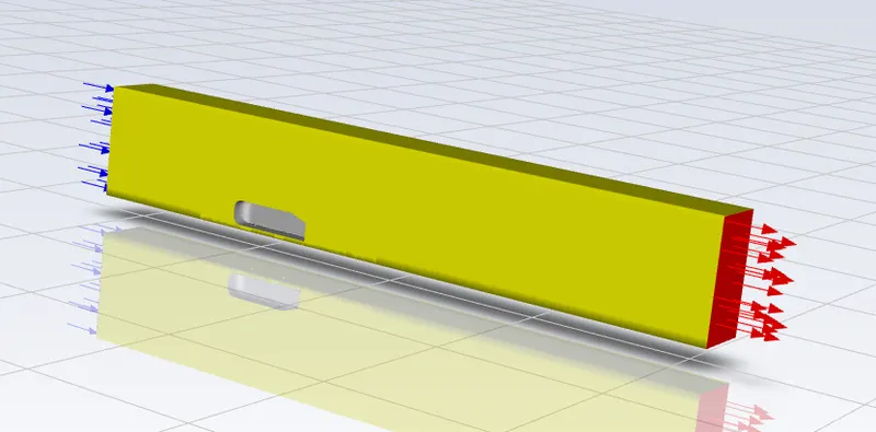
The setup:
Velocity contour:
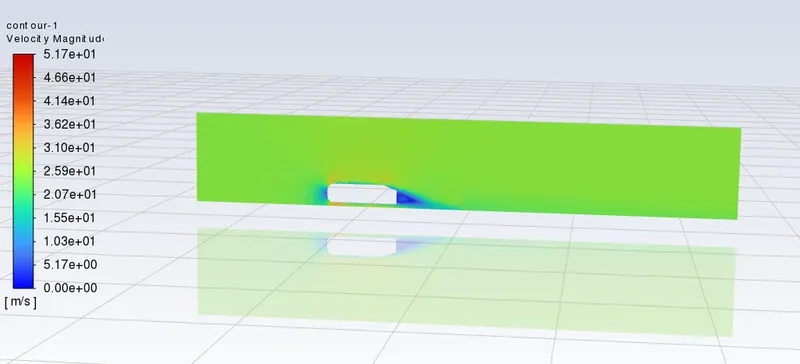
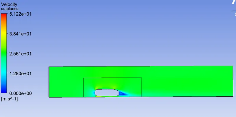
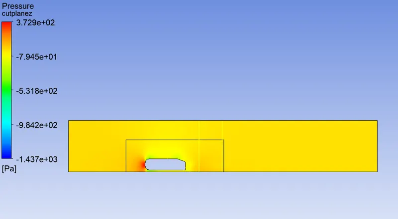
Presuure contour:
Vector contour:
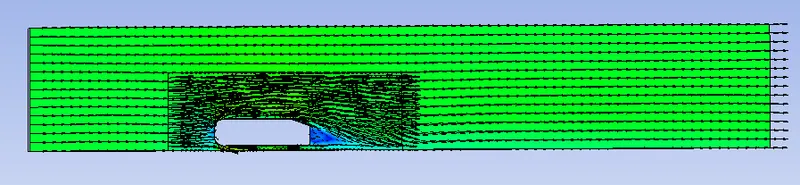
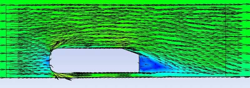
Wake region of the vector contour:
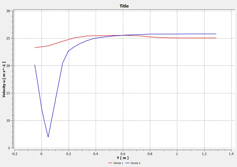
Variation of y with velocity in different regions of the setup:
Case 2:
Outer enclosure : 90mm
Inner enclosure : 40 mm
Face sizing for ahmed body : 5 mm
Inflation for ahmed body - Total thickness : 3.0894mm
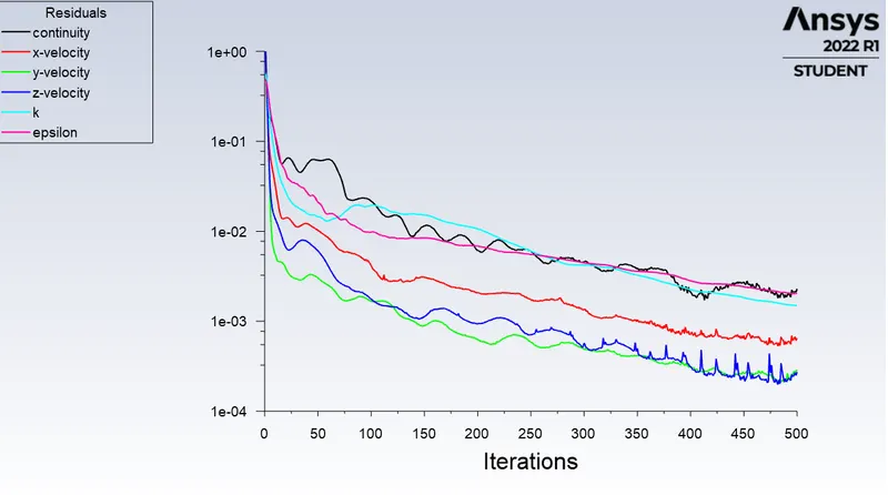
Residuals:
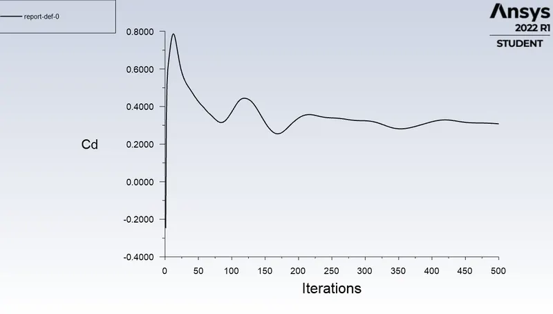
Coefficient of drag:
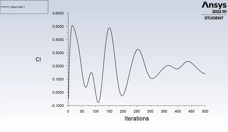
Coefficient of Lift:
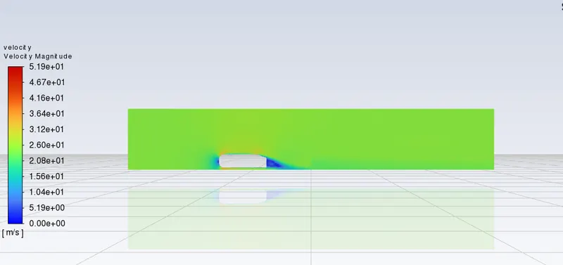
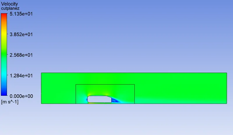
Velocity contour:
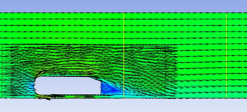
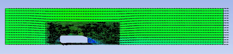
Vector contour:
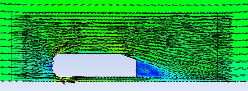
Wake region of the vector contour:
Variation of y with velocity in different regions of the setup:
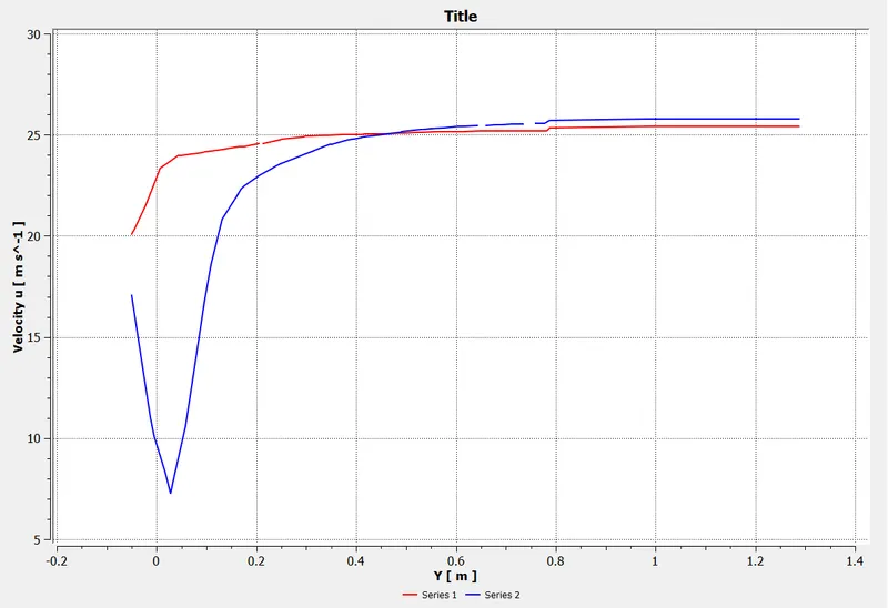
cl = 0.1392
cd=0.3079
Case 3:
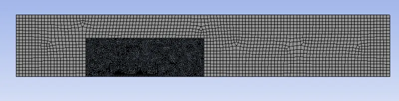
Outer enclosure : 90mm
Inner enclosure : 40 mm
Face sizing for ahmed body : 5 mm
Inflation for ahmed body - Total thickness : 3.0894mm
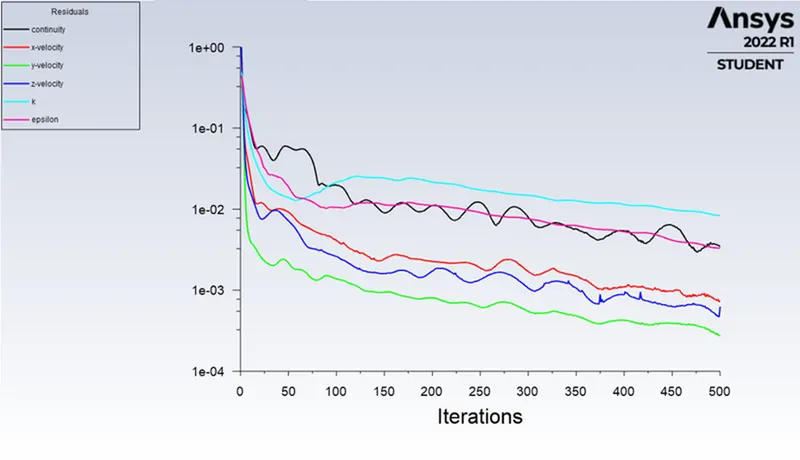
Residuals:
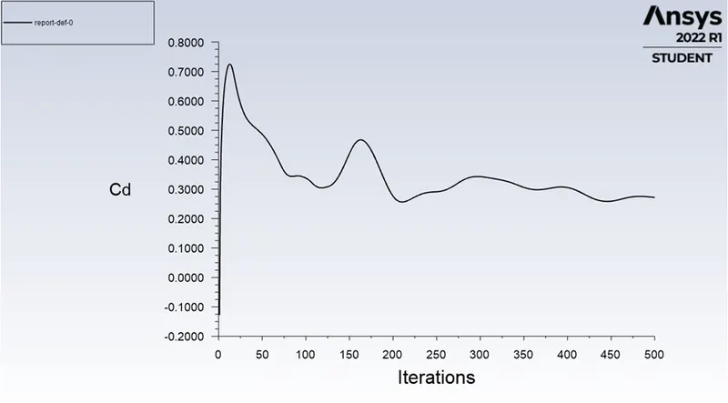
Coefficient of drag:
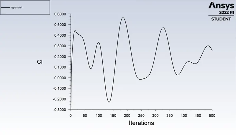
Coefficient of Lift:
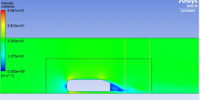
Velocity contour:
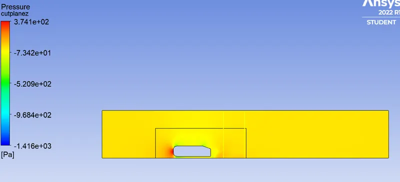
Pressure contour:
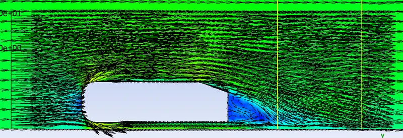
Wake region of the vector contour:
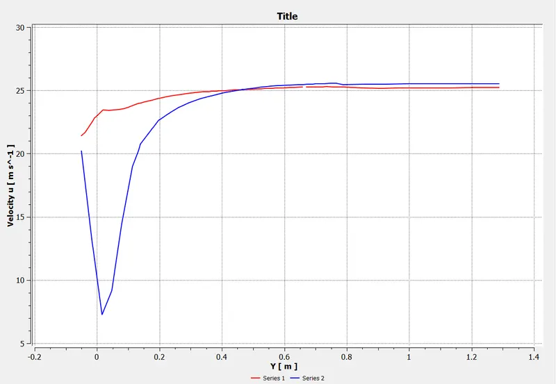
Variation of y with velocity in different regions of the setup:
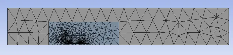
Case 4: Basic mesh:
Default mesh with no sizing and method.
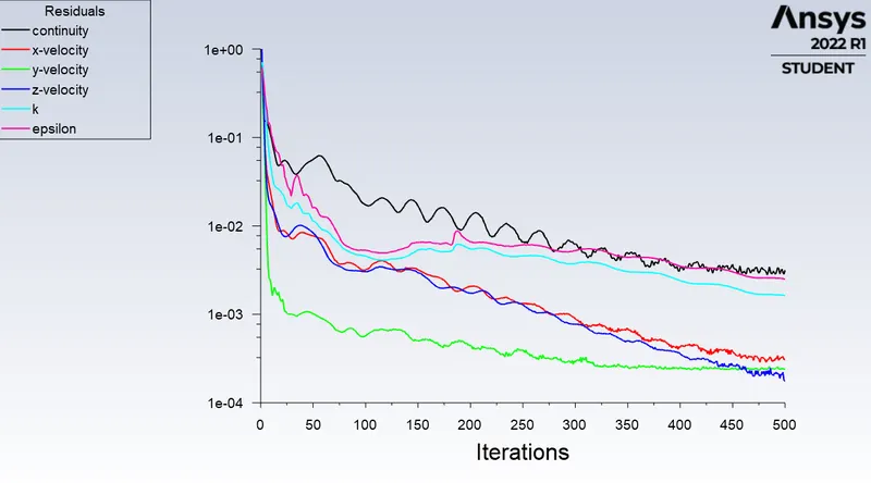
Residuals:
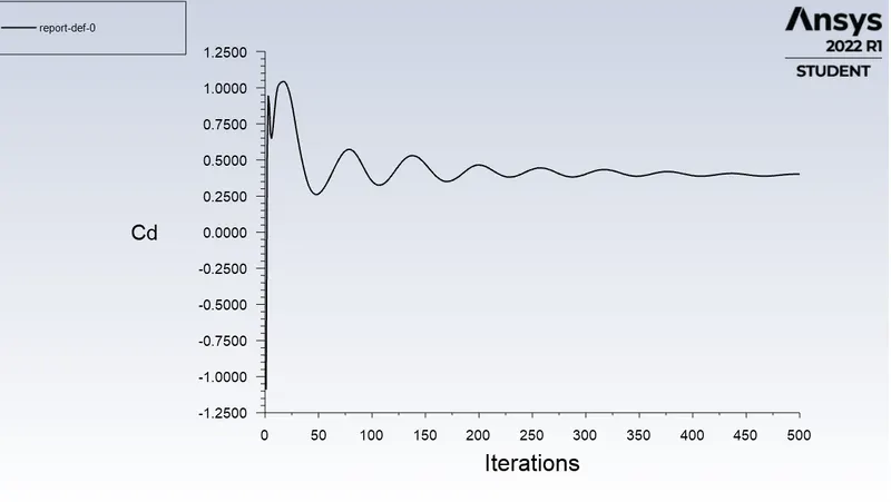
Drag coefficient:
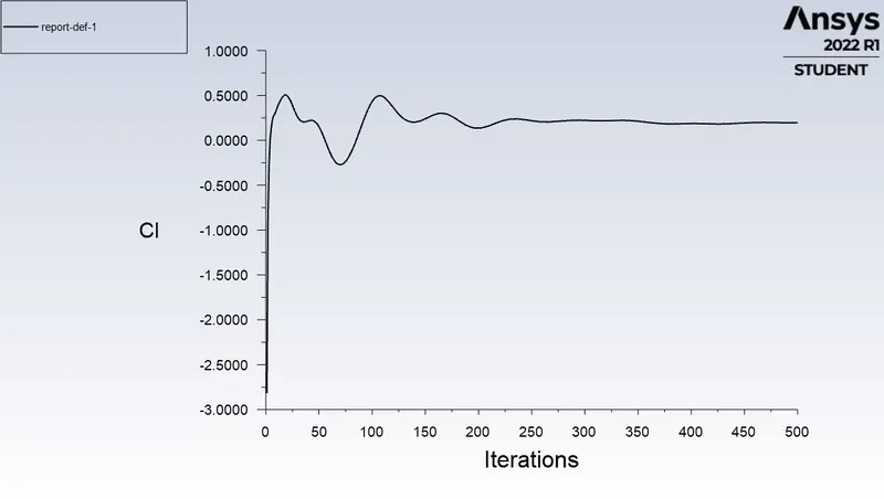
Lift coefficient:
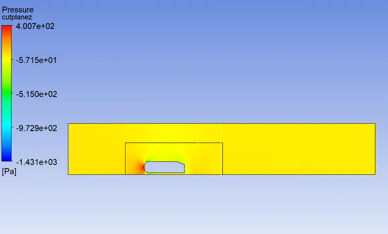
Pressure contour:
Velocity contour:
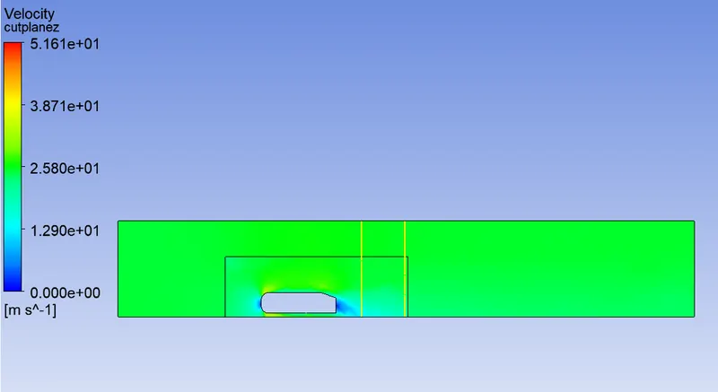
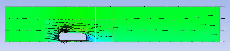
Vector contour:
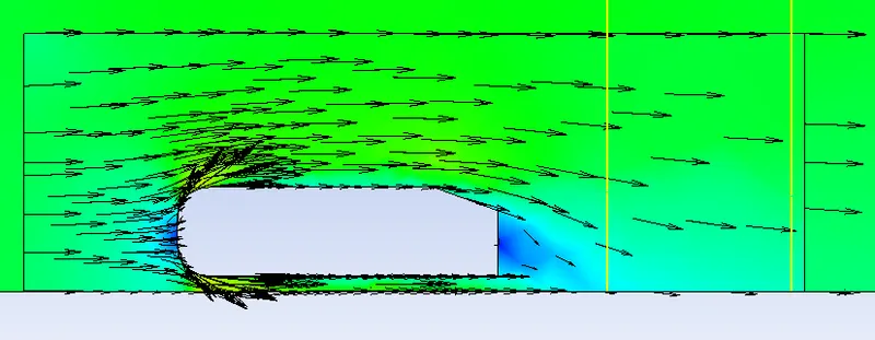
Wake region in the setup:
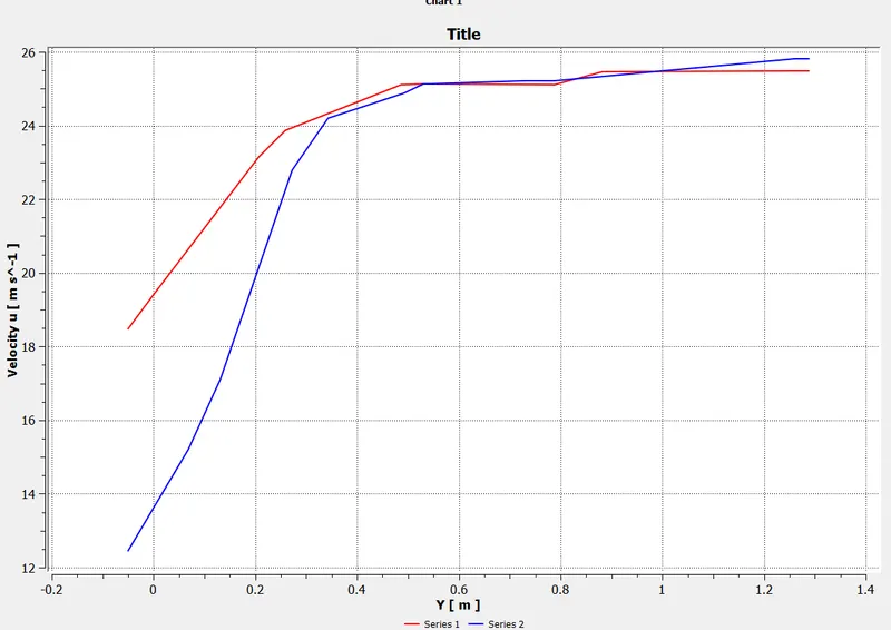
Variation of y with velocity in different regions of the setup:
Inference:
| No .of elements | Cd | Cl | |
| Case 1 | 107418 | 0.318775 | 0.159489 |
| Case 2 | 169810 | 0.3079 | 0.1392 |
| Case 3 | 348995 | 0.27222 | 0.25392 |
| Case 4 | 51878 | 0.40148 | 0.19611 |
Negative Pressure:
When the velocity increases the fluid pressure decreases.The wake is formed due to adverse pressure gradient at the rear end of the vehicle which decrease the fluid velocity or even become reversed causing a flow seperation. The wall shear stress and velocity becomes zero so the wake is formed .These wakes are small vortices which creates negative pressure and these are responsible for the circulation of the velocity nad induces drag forces.
Point of seperation:
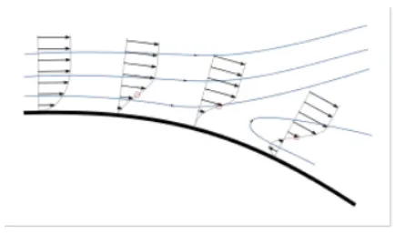
Seperation ocuurs due to adverse pressure gradient encountered as the flow expands,causing an extended region of seperated flow.The part of the flow that seperates the recirculating flow and the centre region flow is called dividing streamline. The dividing streamline attaches to the wall is called reattachment region. So it reaches a equilibrium and the flow attaches with the wall. When the boundary layer seperates ,it creates a shear sublayer and the seperated flow between the shear layer and the wall modifies the pressure.
Conclusion:
1.Simulation was run on the model using different grid depedndencies, with refining the mesh sizes ,y+ factors the error is is reduced in the results.
2.In order to reduce the wake region, the detachment of the fluid seperation should be far awy from the body so the pressure drag can be decreased which influences the drag and lift coefficients.