Week 3 - External flow simulation over an Ahmed body.
1.Objective:
To do external flow over the Ahmed body.
Q1.1 Ahmed Body
- The Ahmed body was described originally by S. R. Ahmed in 1984
- The Ahmed body is a simplified vehicle model. The airflow around the Ahmed body captures the essential flow features around an automobile and was first defined and characterized in the experimental work of Ahmed.
- The Ahmed body is a benchmark model widely used in the automotive industry for validating simulation tools. The Ahmed body shape is simple enough to model, while maintaining car-like geometry features.
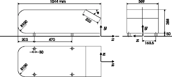
Fig: Ahmed Body Dimension
- The simple geometrical shape has a length of 1.044 meters, height of 0.288 meters, and a width of 0.389 meters.
Q.1.2 Importance of Ahmed body
- The Ahmed body is easy to model, it can be effortlessly utilized for researching various properties like turbulence, drag coefficient, wake region, lift forces, velocity magnitude at various regions of the car, magnitude of pressure around the car which helps in determining what will be resistance, fuel.
- It has become a benchmark of the CFD simulation of the famous external aerodynamic test case.
Q2.The reason for the negative pressure in the wake region.
- The flow around a road vehicle is a rather complex phenomena that includes massive separation and development of a wake. The boundary layer on the surface of the body eventually separates as it reaches the rear edge and the separated flow experiences high shear and forms a wake. The aerodynamic resistive force that a road vehicle experiences is mostly due to pressure which means that there is a large pressure difference at the front and the rear of the body. The lowpressure region at the rear is due to the existence of a wake which is made up with multiple length and time scales and is inherently unsteady and three dimensional. These flow features arise due to the bluffness of the geometry and this bluffness is associated with comfort and functionality which cannot be negated. illustrates the common flow features associated with road vehicle aerodynamics.
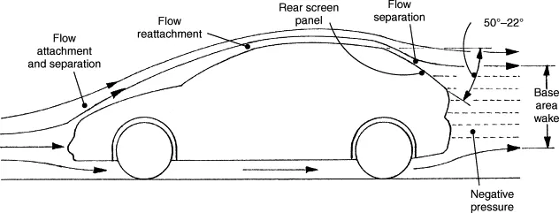
Fig: Negative pressure at wake region
Q3.The significance of the point of separation.
- The separation point is the point where the air stops "sticking" to an object that is moving through the air. When an object is moving through the air, the air molecules push back on it and resist the object's movement - this resistance is called pressure drag.
- Flow separation or boundary layer separation is the detachment of a boundary layer from a surface into a wake. Separation occurs in flow that is slowing down, with pressure increasing, after passing the thickest part of a streamline body.
- Flow separation occurs because the boundary layer is traveling against an adverse pressure gradient. The pressure increases in the direction of flow and velocity decreases. Eventually the velocity of the boundary layer goes to zero and detaches from the surface.
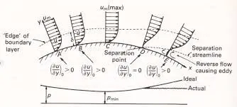
Fig: Point of separation
2.Procedure
2.1 Geomentry
As the body is perfectly symmetric, we can run the simulation by considering the only half body. This is the best practice where you can save on the number of cells and get the results faster as well.
The geomentry which is provided with the challenge needs a modification which you should be able to do at this stage of a course. we need to use the 'split body' command in SpaceClaim to perform the operation and then you can use the symmetry boundary condition in fluent to perform the simulation.
1. Load the Ahmed body model into spaceclaim and convert the units from millimeters to meter.
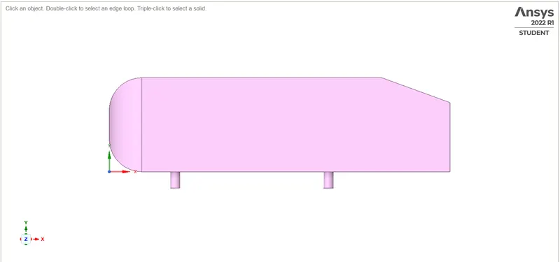
Fig: Geomentry Model
2. Go to prepare and click on the enclosure and select the Ahmed body. Enter the enclosure dimensions. And uncheck the symmetric option before giving value.
3. After both enclosure is created, we can check interference and avoid overlapping of meshing in the 2nd enclosure by applying check interference and delecting the overlap. This is automatically done by spaceclaim when the interference option is selected inside prepare.
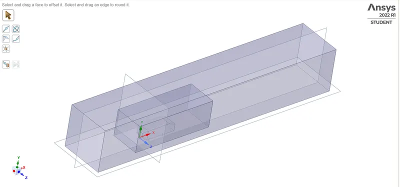
Fig: Two enclosure with cut plane in 3 Dimensions.
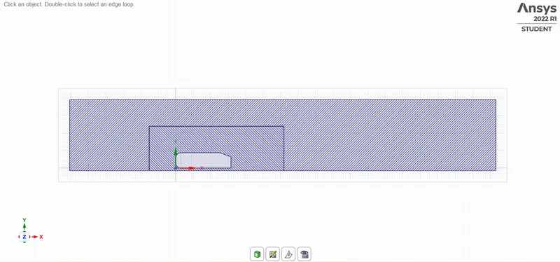
FIg: Enclosure interference
4. After achieving the split, hide the Ahmed body, suppress the physics and go to properties, and select share topology. Now the mesh from both the enclosures can share the information and have symmetry.
2.2 Mesh
5.Multizone: This option is used to generate mesh in the outer region which is primarily hexahedral
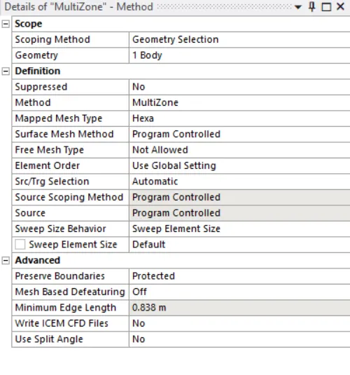
Fig: Multizone sizing
6.Body sizing: This option is used to refine the layer inner enclosure of the wind tunnel. The increased size gives us more accurate results near the ahmed body. Element size 0.05m
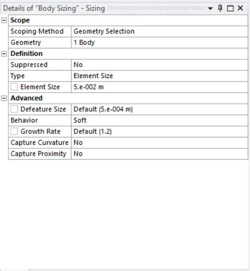
Fig: Body sizing
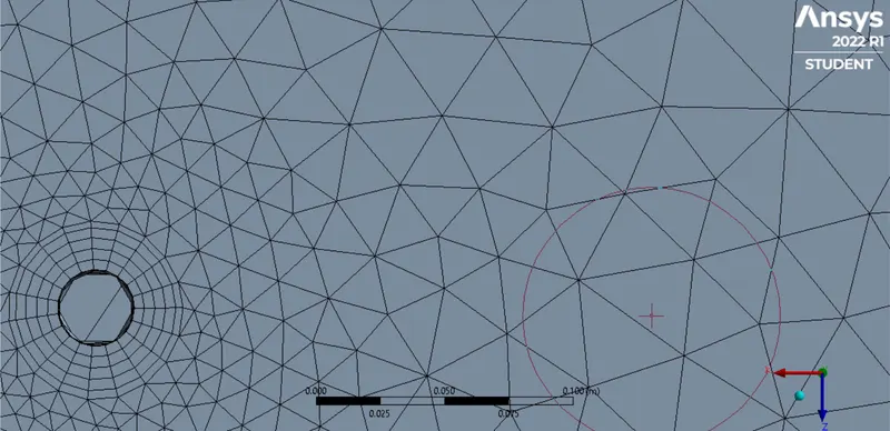
7. Edge Sizing
This method is used to ensure that the legs of the ahmed body are circular and not ployhedral
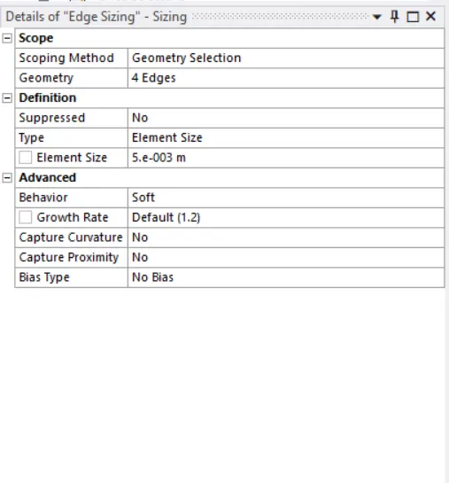
Fig: Edge sizing
8. Inflation sizing:
This option is used to accurately capture the boundary layers on the surface of the body.
First layer thickness=0.005m
Incremental ratio = 1.2 times of previous layer (or) 20% of previous layer
Total layer and Total thickness in this problem = 5 layers and 0.0005m
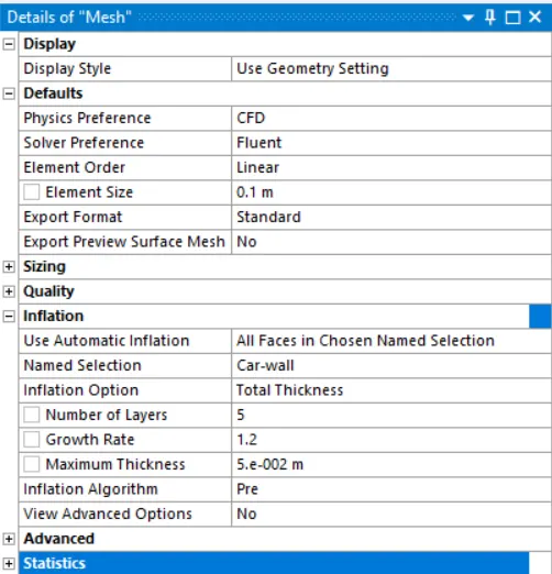
Fig: Inflation sizing
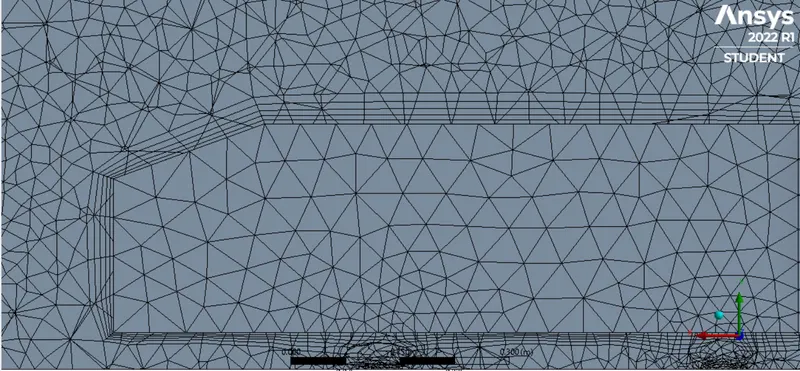
Fig: Inflation layers
Mesh
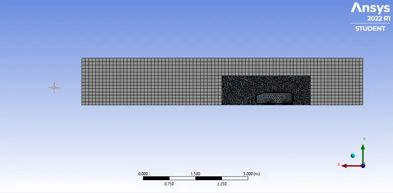
Fig:Final mesh
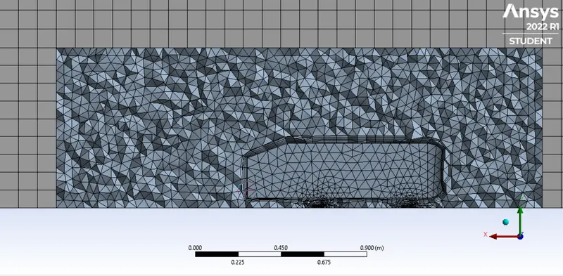
Fig: Diamond meshing of Inner enclosure
2.3 Setup and solution
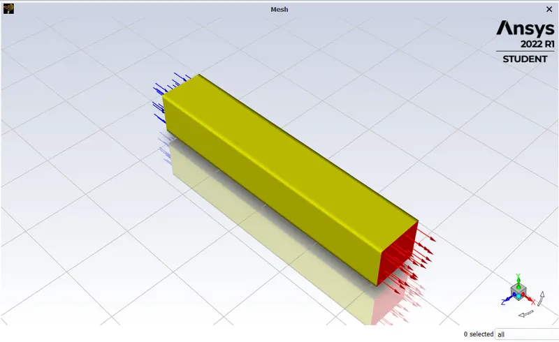
Fig: Mesh
9.Exit mesh and open setup. First, Check mesh, it is throwing no error then only we can proceed further. We are going to do Density based steady state simulation, So choose these options on task page.
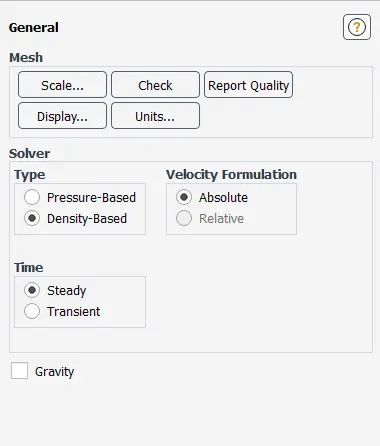
Fig: Task page
10. Go to physics menu and select viscous model. It will open a menu, choose realizable K-omega model and close it.
Reynolds Number:

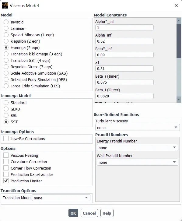
Fig: Viscous model parameters
11.Click on material and choose air as working fluid. check working fluid by clicking on cell zone conditions option, if it is air then proceed.
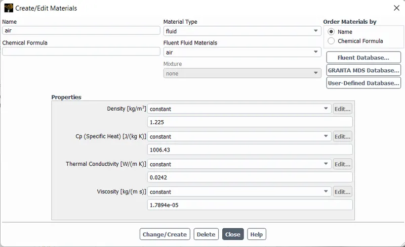
Fig: Assigning Mateials
12.Now go to boundaries option to set boundary conditions. Select inlet x and click on option edit. It will open a menu, Where it is thermal radiation, momentum etc. Put the value of velocity as 25m/s and go to thermal parameter to set temperature as 300k
13.We want to generate temperature report of outer layer of car body velocity
14.Now click on intialization to calculate approximate values of velocity and pressure.
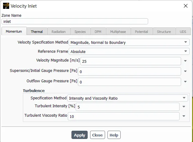
Fig: velocity inlet
15.Change the number of iteration 200 and click on calculate.
2.4 Results
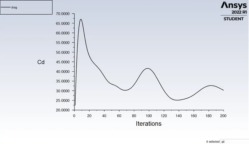
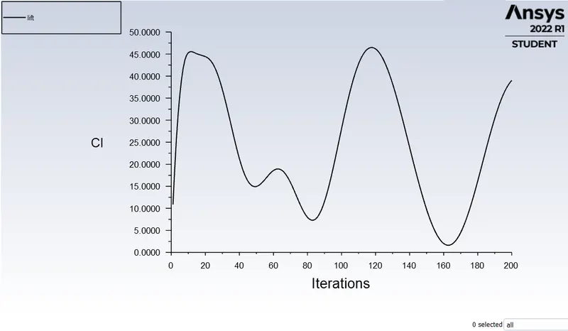
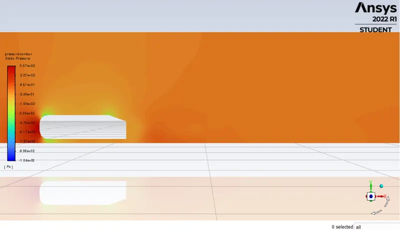
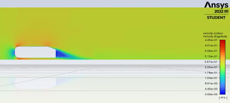
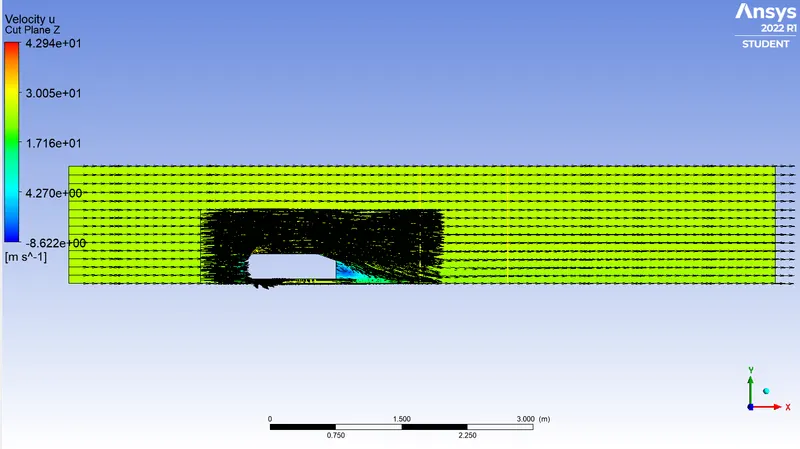
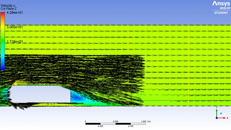
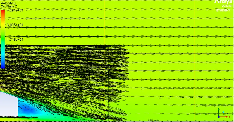
In this Ahmed body is helps to know the outside of the car body velocity, negative pressure at wake region, drag and lift. We used two different turbalent solvers for it first was realized k-epsilon(initial mesh) and second was k-omega(Finner mesh) SST.
Residual
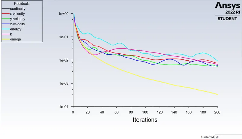
Drag co-efficient of car body
Lift co-efficient of car body
Pressure contour
Velocity contour
vector contour
zoom the wake zone (vector contour)
futhur zoom the wake zone (vector contour)
Mesh with velocity contour
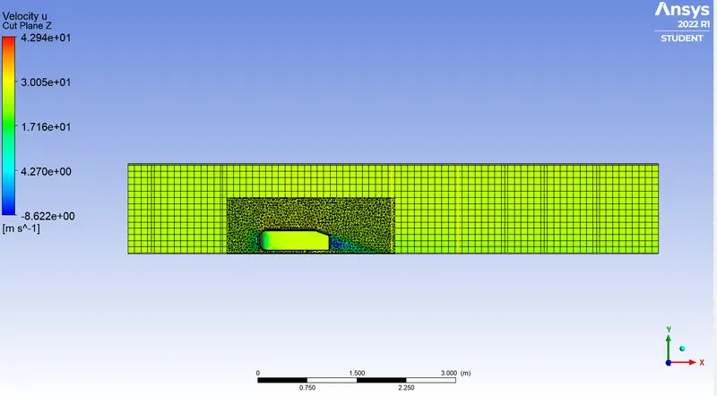
Mesh with velocity contour
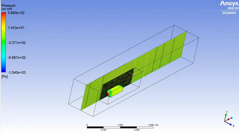
velocity contour
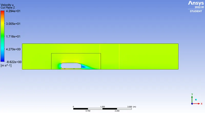
velocity contour with mesh of car outer body
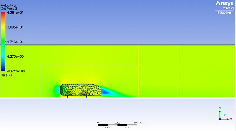
zoom the wake zone(velocity contour)
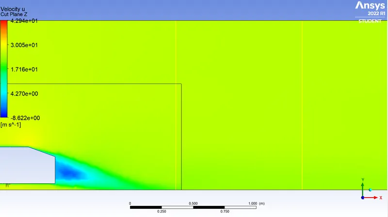
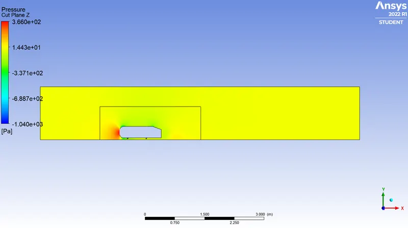
Pressure contour
zoom the wake zone(pressure contour)
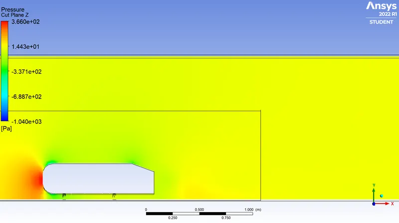
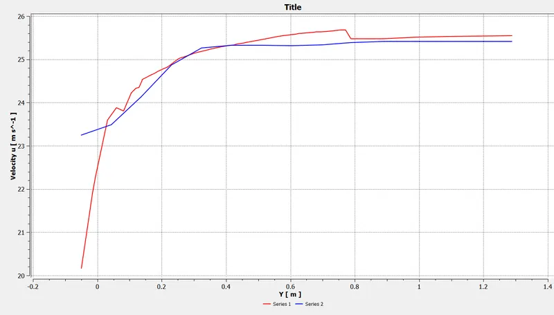
Chart of line 1 & 2 velocity
4.Grid Dependancy:
A Grid Dependance Test is used to as certain whether the final values of the solution are dependent on the mesh or not. This is an important test to ensure the simulation results are correct.
| Mesh quality(m) | Body sizing(m) | Edge sizing(m) | Number of nodes | Number of elements | |
| 1st Refindment | 0.08 | 0.045 | 0.005 | 74165 | 223039 |
| 2nd Refindment | 0.075 | 0.045 | 0.005 | 76961 | 225343 |
| 3rd Refindment | 0.08 | 0.04 | 0.005 | 87758 | 295141 |
| 4th Refindment | 0.08 | 0.04 |
0.004 |
89097 | 299319 |
| 5th Refindment | 0.075 | 0.040 | 0.004 | 91908 | 301331 |
| 6th Refindment | 0.070 | 0.040 | 0.004 | 100285 | 308994 |
| 7th Refindment | 0.070 | 0.035 | 0.0035 | 122651 | 429386 |
5.Conclusion:
- The velocity decreases at the front of the Ahmed body because of the impact of the fluid with the body due to which the pressure increases.
- Due to the impact, there is an initial acceleration of the flow on the top, followed by which the velocity decreases gradually.The pressure decreases in the regions where velocity increases.
- The flow once again speeds up because of the sudden change in geometry at the end of the top surface, which results in the separation of flow and the formation of the wake.
- This wake formation leads to a significant reduction in pressure at the region of the Ahmed body as compared to the front the region, where pressure is higher due to the impact of flow on the body, and this results in the generation of a drag force.