Week 3 - External flow simulation over an Ahmed body.
The aim, Introduction, Theory
The Ahmed body, even though it does not replicate the exact shape of a vehicle body used in the current industry, the shape of the rear of the vehicle is imperative in capturing the forces, pressure and velocity in the wake region of any generic vehicle.
The airflow around the body captures the important flow features required in designing any vehicle.
Once the numerical values are validated, this serves as a basis for designing the complete body further.
Significance of the point of separation:
Due to viscous nature of any fluid in real life, the velocity of the fluid near the wall region will be very low due to no slip condition eventually forming a boundary layer.
The flow velocity is zero at the surface to satisfy the no slip boundary condition. Within the layer, flow momentum is low as it experiences strong viscous flow resistance. This makes the boundary layer sensitive to external pressure forces. If pressure is increasing in direction of flow, then there will be an adverse pressure gradient situation. In addition to presence of strong viscous force, the particles now need to overcome the increasing pressure forces. This results in a reversal or stoppage of fluid particles at some point along the flow, causing the particles to move away from surface.
This is called boundary layer separation.
Negative pressure in wake region:
The wake region is the region in the rear of Ahmed Body. This is a critical region were flow variables are ascertained and their effects studied.
As discussed, the fluid particles remain attached in case of a favourable pressure gradient. In case of an adverse pressure gradient, the particles come across increasing pressure forces along the direction of flow. As the pressure increases in rear of Ahmed body, the particles experience an adverse pressure gradient. Consequently, the flow separates from the surface thereby creating a turbulent region called wake.
The pressure in wake region remains low as flow separates and a drag is produced.
Solving and Modelling approach, Pre-processing and solver setting
For Solving and Modelling approach,kindly refer the video, the link to which has been attached herein.
The solver selected here is the K-epsilon model as 'Y plus' for standard wall function is taken as 200. We understand from literature, for turbulent region of the flow, a value of 30-300 must be taken for Y plus.
Y plus is basically a dimensionless number which gives the user an idea of what should be the distance from wall for first node in order to capture the flow physics, whether it be viscous sublayer, which is very close to wall ( Y plsu between 1 and 5), or the turbulent region, (Yplus 30-300).
In this challenge, I have simulated flow for values of Y plus ranging from 50 to 200 with various mesh size configurations.
The setting giving best results of drag coefficient has been documented, the snippets of the same shown in ensuing paras.
Outer Enclosure mesh size = 90 mm
Inner enclosure and Ahmed body wall mesh size = 35 mm
Ahmed Body leg size = 3 mm.
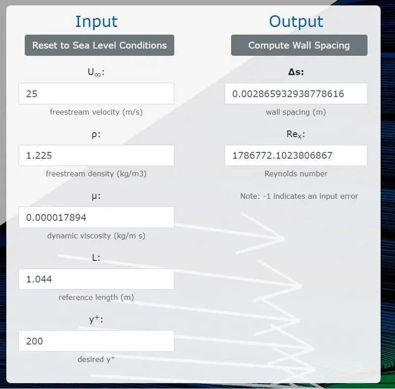
Inflation layer corresponding to Y plus of 200, first layer thickness = 2.8659 mm for a velocity of 25 meters per second.
Standard air density of 1.225 kg per square meter.
viscosity value of 0.000017894 kg/ms
Reference length = 1.044 meters.
Calculations are done from pointwise.com, a snippet of the same has been attached.
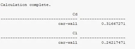
Plots showing drag and lift coefficients have been attached below with their values.
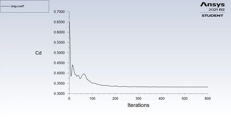
Drag Coefficient
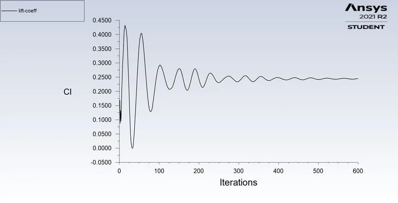
Lift Coefficient
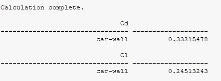
Drag and Lift Coefficient
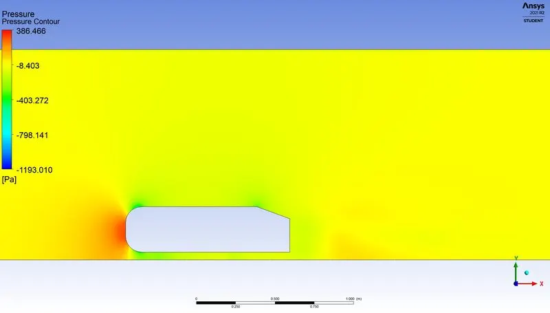
Pressure contour in wake region
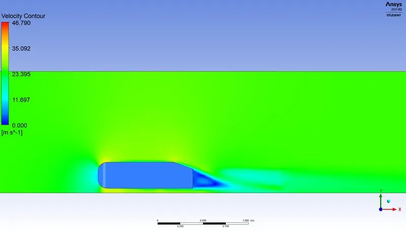
Velocity contour in wake region
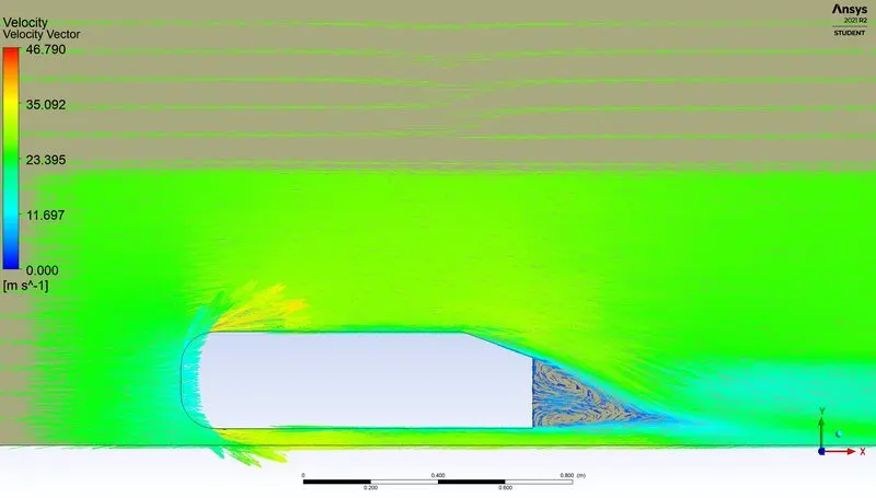
Velocity vector plot
Grid Independency test for various mesh sizes and Y plus value of 200
- CASE 1
Outer Enclosure mesh size = 90 mm
Inner enclosure and Ahmed body wall mesh size = 30 mm
Ahmed Body leg size = 2 mm
- CASE 2
Outer Enclosure mesh size = 90 mm
Inner enclosure and Ahmed body wall mesh size = 30 mm
Ahmed Body leg size = 3 mm
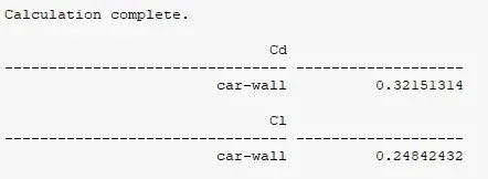
- CASE 3
Outer Enclosure mesh size = 90 mm
Inner enclosure and Ahmed body wall mesh size = 35 mm
Ahmed Body leg size = 3 mm
- CASE 4
Outer Enclosure mesh size = 90 mm
Inner enclosure and Ahmed body wall mesh size = 40 mm
Ahmed Body leg size = 3 mm
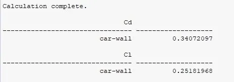
- CASE 5
Outer Enclosure mesh size = 90 mm
Inner enclosure and Ahmed body wall mesh size = 45 mm
Ahmed Body leg size = 5 mm
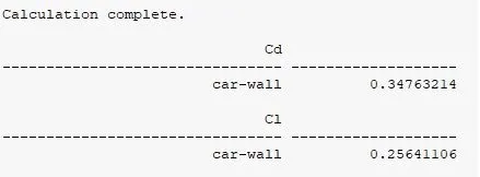
- CASE 6
Outer Enclosure mesh size = 95 mm
Inner enclosure and Ahmed body wall mesh size = 50 mm
Ahmed Body leg size = 5 mm
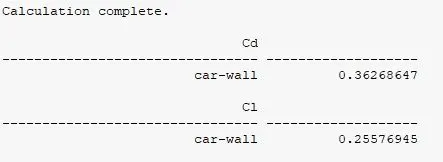
The order of this is, the most refined case is shown in case 1 and the coarse one is shown last.
Attaching plots of Drag Coefficients against various values of Y plus in turbulent region ranging from 30 to 300 without changing mesh sizes
Y plus = 30
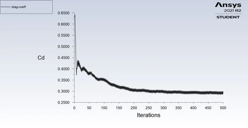
Y plus = 50
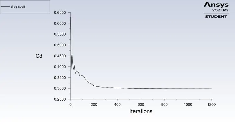
Y plus = 100
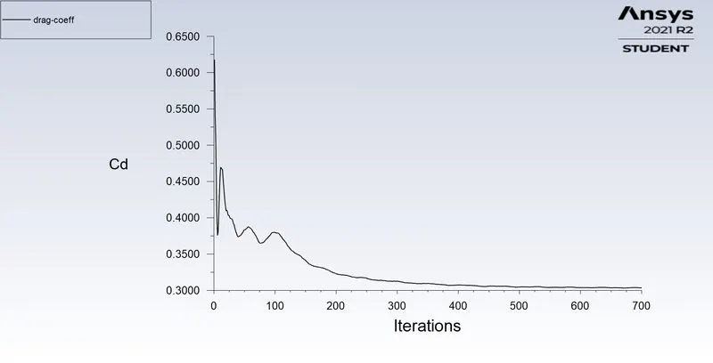
Y plus = 130
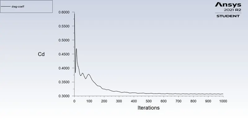
Y plus = 130
Y plus = 150
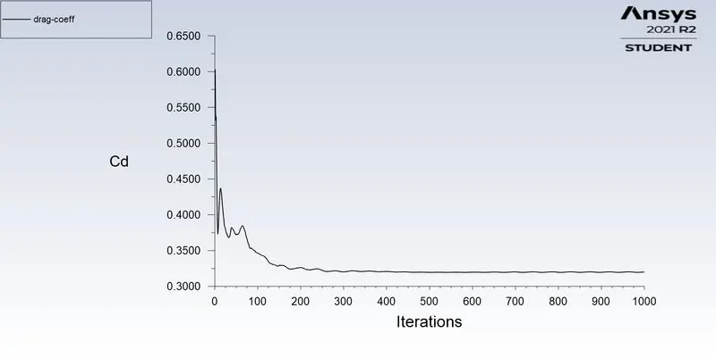
Y plus = 200
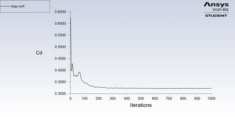
Conclusion:
- Reducing the mesh sizes increases the number of elements in computational domain, this in turn increases the computational time but gets us closer to the results of drag coefficient.
- The reason for selecting a Multizone type of mesh style for the outer enclosure was to have hexahedral mesh in this enclosure as it has a standard reactangular cross section. It is a general practise to select structured mesh were ever possible to reduce the complexity of solving algorithm.
- Of course, this cannot be undertaken for more complex shapes.
- For this reason, we have taken a tetrahedral mesh, an unstructured mesh, in the inner enclosure to have better communication between the enclosure and car wall.
- Using Y plus values to generate mesh in turbulent case at the car wall surface affects the accuracy of lift and drag coefficients.
- Also tried to run the simulation for Y plus values between 1 and 5, the solution diverged even after running the simulation using k omega SST solver. Could not ascertain the reason for the same.
- A high turbulent zone is witnessed at the wake zone and negative pressure gradient as well.