Week 3 - External flow simulation over an Ahmed body.
Aim :
To run external flow simulations over an Ahmed body with the given conditions.
Objective :
- To describe the Ahmed's body and its importance.
- To explain the reason for the negative pressure in the wake region.
- To explain the significance of the point of separation.
- To plot velocity and pressure contours.
- To plot the drag coefficient plot for a refined case and verify it with the experimental data.
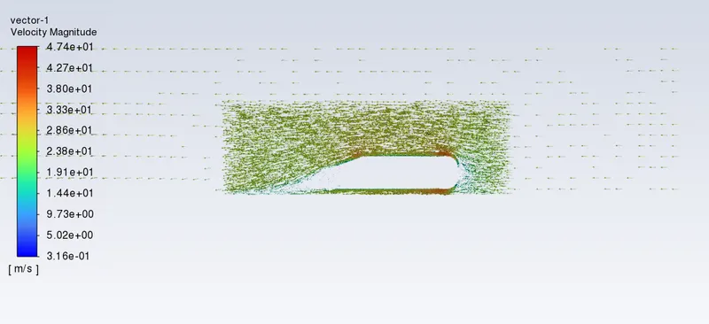
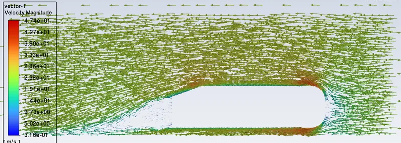
- To plot the vector plot which clearly shows the wake region.
- To perform the grid independence test and provide the values of drag and lift with each case.
Project methodology :
In this project, the flow over an Ahmed body is simulated and post-processed in Ansys Fluent. Initially, Ahmed body is imported in SpaceClaim and enclosure is assigned just like a wind tunnel. The Ahmed body is meshed for different element size and it with an added inflation layer to perform grid dependency test. K-epsilon turbulence model (Realizable with standard wall functions) is used to simulate the flow conditions. The coefficient of drag and lift is calculated for the respective cases and validated with standard reference to compare accuracy of the numerical results.
Calculations :
The Reynolds number for the flow can be given as,
`Re=ρVL_Cμ`
`Re=(1.225×25×1.044)/(1.7894e^(−5))`
`Re=1.7868×10^6`
The resulted Reynolds number is high, which is efficient to create turbulence and flow separation. The Reynolds number will same for all the case studies as the velocity is not changed.
Theory :
Ahmed body :
- Ahmed body is a generic car body (a simplified car model) i.e the flow of air around Ahmed body captures the essential flow features around an automobile.
- The Ahmed body was first created by S.R. Ahmed. It is an important benchmark for aerodynamic simulation tools. It will be clearly shown in the sketch below that it has a length of 1.044 meters, a height of 0.288 meters, and a width of 0.389 meters. It also has 50-millimeter cylindrical legs attached to the bottom of the body and the rear surface which has a slant that falls at 20 degrees.
- The flow for the model is turbulent which is based on velocity and body length.
Importance of Ahmed body :
- The drag force is an important factor considering fuel consumption. As the drag force increases the fuel consumption also increases which in turn becomes expensive for the car owners. As the burning of fossil fuels becomes an issue, the manufacturers are pressing for fuel-efficient cars. One of the main factors considering the car is fuel-efficient or not is the car's geometry.
- Complex-shaped cars are very challenging to model and it's difficult to quantify the aerodynamic drag computationally. The Ahmed body is a benchmark model widely used in the automotive industry for validating simulation tools.
Negative pressure in the wake region :
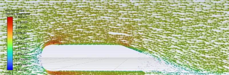
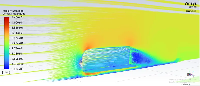
- When the air moving over the vehicle is separated at the rear end, it leaves a large low-pressure turbulent region behind the vehicle which is known as the wake. This contributes to the formation of pressure drag which affects the vehicle performance.
- When the vehicle is moving at a certain velocity the fluid imparts viscous force to the vehicle as long as it is in the viscous sublayer of the boundary. When the fluid reaches the rear end of the vehicle it gets detached from the surface of the body causing negative pressure in the wake region. The movement of the fluid around the vehicles depends on the geometry of the car and the Reynolds number.
Significance of point of separation :
The point of separation will occur when there is a discontinuity in the surface or a region of the negative pressure gradient.
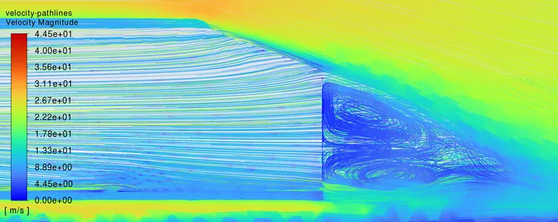
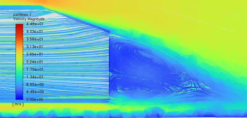
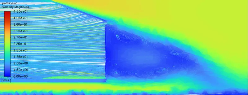
When the flow is attached to the body of the vehicle the viscous force will increase which will increase the pressure and a decrease in velocity before the rear end of the vehicle. As soon as the air encounters the sharp turn causing the velocity decreases resulting in the negative pressure region which is in the wake region. The recirculation region happens beyond the point of separation. If the rate of change of pressure is large the mixing process will not occur and the boundary layer flow stops. The above figure shows that at the point of turning the flow gets separated from the boundary layer and there is a region of recirculation after which the flow attaches itself to the boundary layer. In order to reduce the separation of fluid from the boundary layer, it is advisable to have a smooth edge to reduce the effect of drag on the vehicle.
Y plus Value :
To check if the mesh is fine enough to catch the boundary layer near the walls, a measurement called y+ describing a dimensionless wall distance is often used.
`y+=(u∗.y∗)/nu`
where s,
u∗ is the velocity at the wall
y∗ - cell length at the wall
`nu` - kinematic viscosity.
The grid quality, as mentioned above for y+, is another important measurement. The wall boundary layer, for viscous simulations, should be meshed according to the y+ equation and is the finest meshed area in the grid and we need to ensure that our y+ values are within a certain range. It's important to ensure Y+ values are not so large that the first node falls outside the boundary layer region. If this happens, then the wall functions used by the turbulence model may incorrectly calculate the flow properties at this first calculation point which will introduce errors into pressure drop and velocity results.
Solution and Results :
Dimension of a ahmed body :
Geometry :
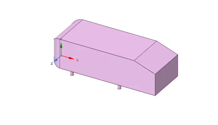
- Import the step file of the ahmed body in the spaeclaim.
Body after enclosure :
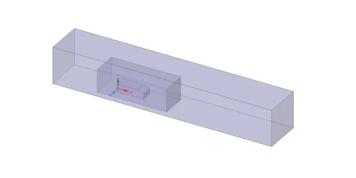
- An enclosure is a solid around a body or bodies that has a cushion around the enclosed solid(s). Box enclosure has been made to cover the ahmed body. The dimension of the enclosure is 2 meter towards left from the front side of the ahmed body and 5 meter towards right from the rear end of the body and again 1m from the top towards up and at bottom 0 meter.
- For sides 0.5 meter is given in either sides.
- Another enclosure is made inside the previous one to reuce the computational time and to capture physics effectively near the walls and in the wake region.
- The dimension of this enclosure is calculated from the base line simulation with respect to the wake region which is 0.5 meter towards left from the front side of the ahmed body and 1 meter towards right from the rear end of the body and again 0.5m from te top towards up and at bottom 0 meter.
- Enclosures are used to simulate fluid.
After spliting the body :
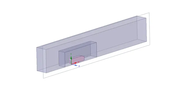
- Though the body is symmetry we cut the body into half in order to reduce the number of elements.
- Then uncheck the ahmed body and suppress for physics since we are concentrating physics at the outer side of the ahmed body.
- Then we check for the interferance inorder to avoid the mesh overlap and share the topology.
Mesh :
Mesh independent study :
The K-epsilon turbulence model with varied mesh refinement is used to perform mesh dependent study. The drag coefficient obtained from these case studies though vary in second decimal places but accounts significant for error percentage. It is obvious to have more accurate results with mesh refinement. In drag analysis it is important to have more refined mesh at external surface and in the wake region to capture pressure and viscous effects. Though the case studies shows negligible variation but in terms of drag coeffcient such variation is unfruitful (completely changes the definition of the external body). The study performed can be asserted as "Mesh dependent study", as the approximation varies significantly as a function of mesh refinement.
Case 1 :
Mesh Details :
| Enclosure 1 Mesh Method | Multizone | Element size = 105 mm |
| Enclosure 2 | Sizing (Body sizing) | Element size = 50mm |
| Car-wall (Leg sizing) | Sizing (Edge sizing) | Number of divisions = 40 |
| Y value (Height of first cell centroid from the wall) | 2.8mm | -- |
| Number of inflation layers | 5 | -- |
| Growth rate | 1.2 | -- |
| Inflation type | Total thickness | 22 mm |
| Total number of cells | 97315 | Coarse |
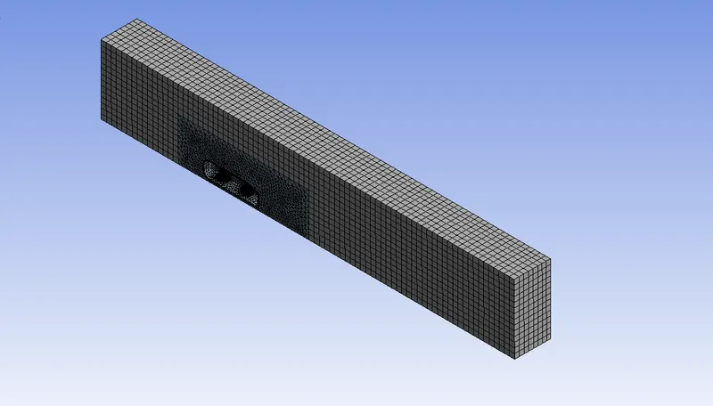
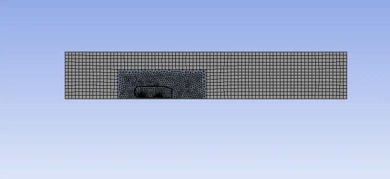
Enclosure(1) = Hexahedral meshes and Enclosure(2) = Tetrahedral meshes.
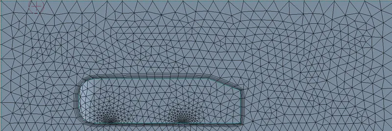
Inflation layer around ahmed body :
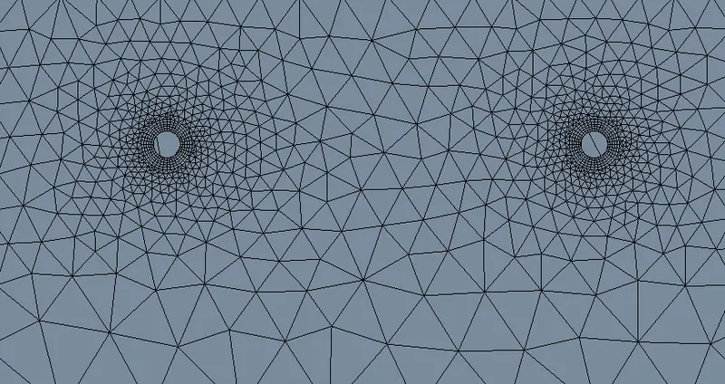
Ahmed body leg refinement :
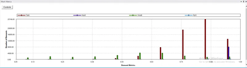
Mesh quality :
1. Naming the geometry as to inlet, outlet, carwall and symmetry.
2. Then using the multi-zone method for the outer encloser with an element size of 0.105m and max size 0.105m as well.
3. For the inner encloser use the body sizing of an element size of 0.05m.
4. Edge sizing is used for the bottom circles in the carwall with a number of divisions 40.
5. Then add inflation layer near the car-wall and choose 7 layers and provide total thickness of 0.022m.
6. Finally check for the mesh quality.
Solution and Results :
Cases :
The simulation set-up will be using Y+ value of 100 and mesh with K-epsilon turbulence model. Steady-state analysis is performed as the matter of concern is the end result.
| Cases | Turbulence model | Mesh |
| Case 1 | K-epsilon (Realizable with Standard wall functions) | Coarse |
| Case 2 | K-epsilon (Realizable with Standard wall functions) | Medium |
| Case 3 | K-epsilon (Realizable with Standard wall functions) | Refined |
Why not k-omega as a turbulence model?
- The K-omega model is well suited for low Reynolds number which accounts for compressibility and shear flow spreading.
- However k-omega (SST-Shear Stress Transport) can be used in this case because of it's capability to incorporate high Reynolds number flows. As it uses K-omega in the inner region of the boundary layer and high Reynolds number model i.e K-epsilon in the outer region of the boundary layer.
- The mesh refinement is an important aspect in K-omega model as it accounts for near-wall effects. The Y+ values should be in the range between 1≤Y+≤10. Mesh refinement should be much fine enough to capture near-wall effects. Accordingly, it uses extensive computation resources for such fine mesh refinement.
- Therefore it is better to opt for K-epsilon as it uses wall functions to estimate near-wall effects and is well suited for higher Reynolds number flows. Comparatively it is computationally cheap which can work with 30≤Y+≤200. This certainly gives mesh refinement flexibility to compute near-wall effects.
|
SETUP |
||
|
Solver Type |
pressure - Based |
|
|
Velocity Formulation |
Absolute |
|
|
Time |
|
|
|
Viscous Model |
K-epsilon | |
|
Material |
Fluid type: Air |
|
|
Cell zones ff_surface |
Fluid type: Air | |
|
Boundaries |
Inlet (velocity inlet) Velocity Magnitude 25m/s Temperature – standard Outlet x (Pressure outlet) Gauge Pressure – 0 pa. Wall - wall Symmetry - symmetry |
|
|
Reference values |
Area = 0.065741`m^2` Density = 1.225kg/`m^3` Enthalpy = 0 `J/(kg)` Pressure = 0 pa Temperature = 288.16K Velocity = 25m/s Viscoity = `1.7894e^(-5)``(kg)/(m.s)` Length of the ahmed body(L_c) = 1.044m |
Residual plot :
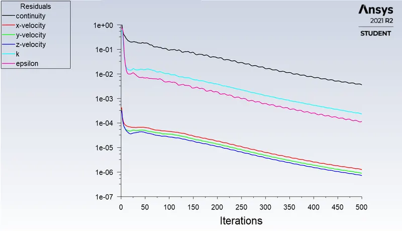
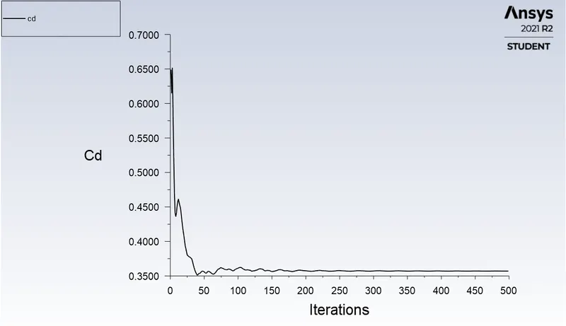
Drag co-efficient plot :
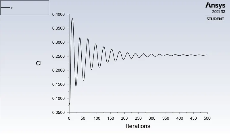
Lift co-efficient plot :
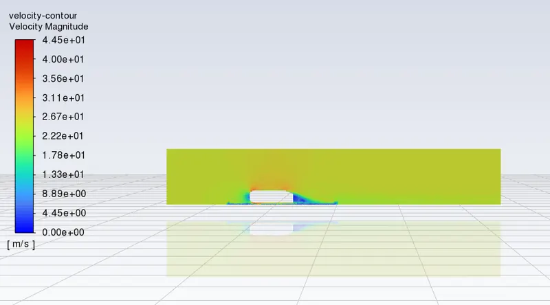
Velocity contour plot :
Pressure at the front side of the car :
Pressure contour plot :
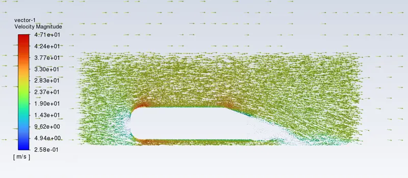
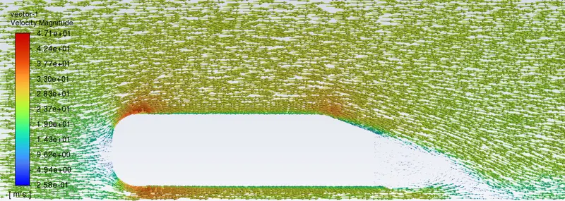
Velocity vector plot :
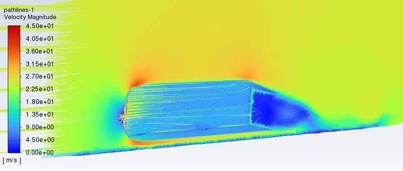
Velocity pathlines :
Case 2 :
Mesh Details :
| Enclosure 1 Mesh Method | Multizone | Element size = 100 mm |
| Enclosure 2 | Sizing (Body sizing) | Element size = 40mm |
| Car-wall (Leg sizing) | Sizing (Edge sizing) | Number of divisions = 40 |
| Y value (Height of first cell centroid from the wall) | 2.8mm | -- |
| Number of inflation layers | 7 | -- |
| Growth rate | 1.2 | -- |
| Inflation type | Total thickness | 38 mm |
| Total number of cells | 149725 | Medium |
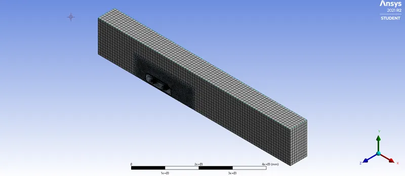
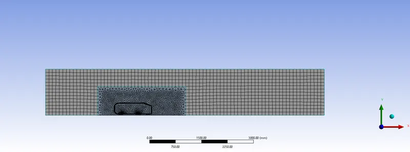
Enclosure(1) = Hexahedral meshes and Enclosure(2) = Tetrahedral meshes.
Inflation layer around ahmed body :
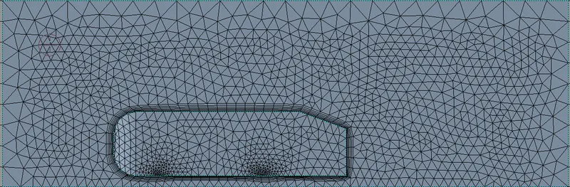
Ahmed body leg refinement :
Mesh quality :
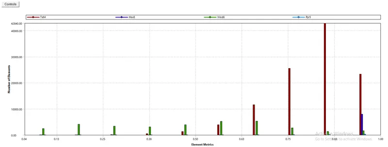
1. Naming the geometry as to inlet, outlet, carwall and symmetry.
2. Then using the multi-zone method for the outer encloser with an element size of 0.1m and max size 0.1m as well.
3. For the inner encloser use the body sizing of an element size of 0.04m.
4. Edge sizing is used for the bottom circles in the carwall with a number of divisions 40.
5. Then add inflation layer near the car-wall and choose 7 layers and provide total thickness of 0.038m.
6. Finally check for the mesh quality.
Solution and Results :
|
SETUP |
||
|
Solver Type |
pressure - Based |
|
|
Velocity Formulation |
Absolute |
|
|
Time |
|
|
|
Viscous Model |
K-epsilon | |
|
Material |
Fluid type: Air |
|
|
Cell zones ff_surface |
Fluid type: Air | |
|
Boundaries |
Inlet (velocity inlet) Velocity Magnitude 25m/s Temperature – standard Outlet x (Pressure outlet) Gauge Pressure – 0 pa. Wall - wall Symmetry - symmetry |
|
|
Reference values |
Area = 0.065741`m^2` Density = 1.225kg/`m^3` Enthalpy = 0 `J/(kg)` Pressure = 0 pa Temperature = 288.16K Velocity = 25m/s Viscoity = `1.7894e^(-5)``(kg)/(m.s)` Length of the ahmed body(L_c) = 1.044m |
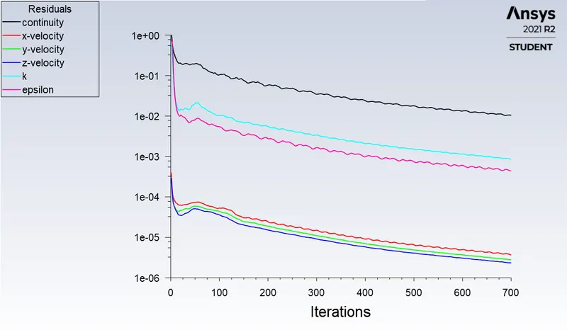
Residual plot :
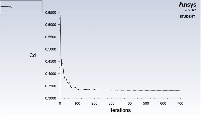
Drag co-efficient plot :
Lift co-efficient plot :
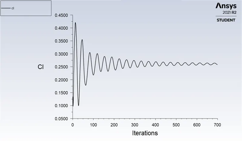
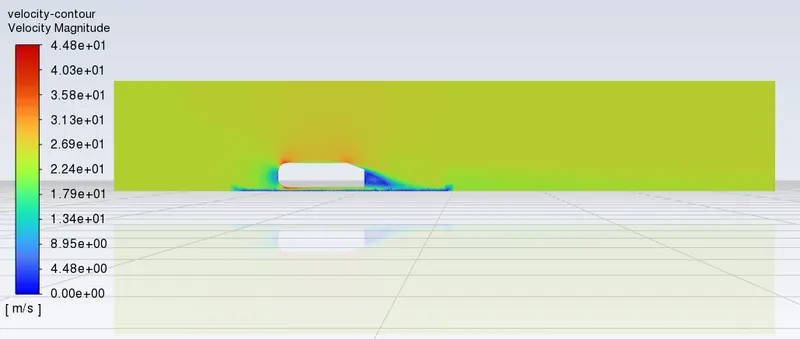
Velocity contour plot :
Pressure at the front side of the car :
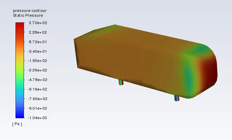
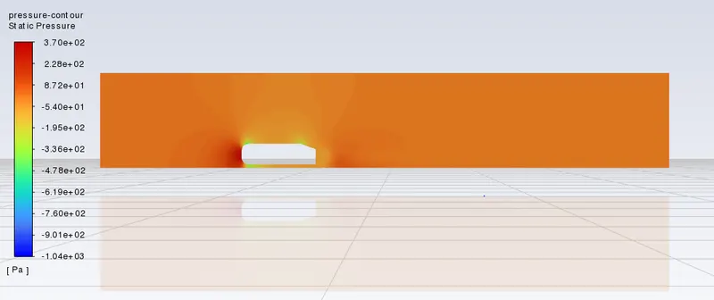
Pressure contour plot :
Velocity vector plot :
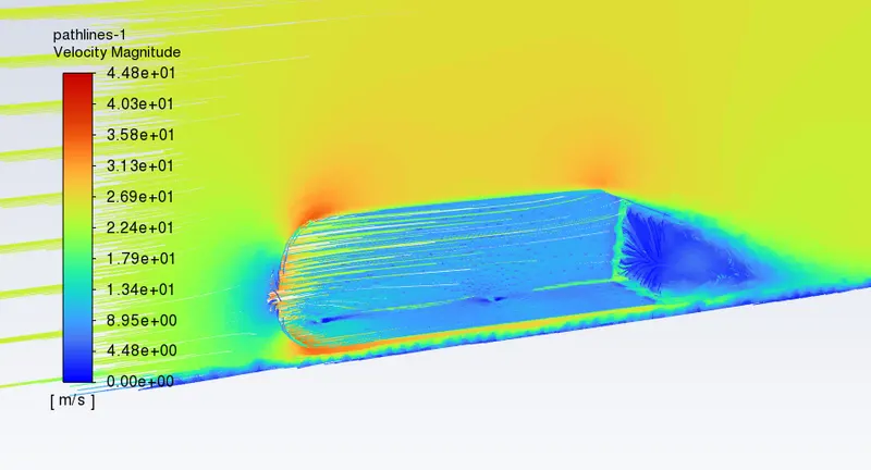
Velocity pathlines :
Case 3 :
Mesh Details :
| Enclosure 1 Mesh Method | Multizone | Element size = 100 mm |
| Enclosure 2 | Sizing (Body sizing) | Element size = 30mm |
| Car-wall (Leg sizing) | Sizing (Edge sizing) | Number of divisions = 40 |
| Y value (Height of first cell centroid from the wall) | 2.8mm | -- |
| Number of inflation layers | 8 | -- |
| Growth rate | 1.2 | -- |
| Inflation type | Total thickness | 48 mm |
| Total number of cells | 277261 | Refined |
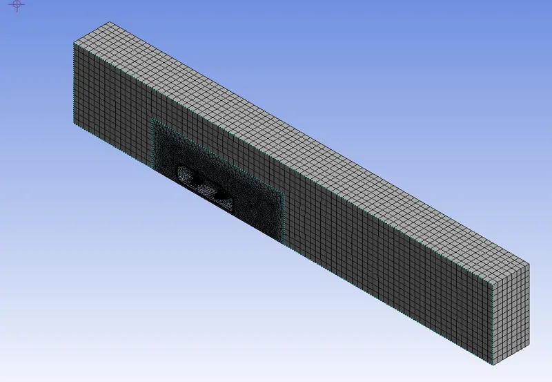
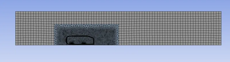
Enclosure(1) = Hexahedral meshes and Enclosure(2) = Tetrahedral meshes.
Inflation layer around ahmed body :
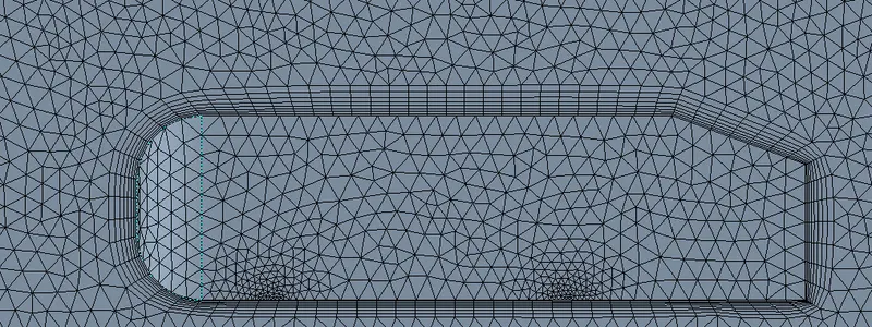
Ahmed body leg refinement :
Mesh quality :
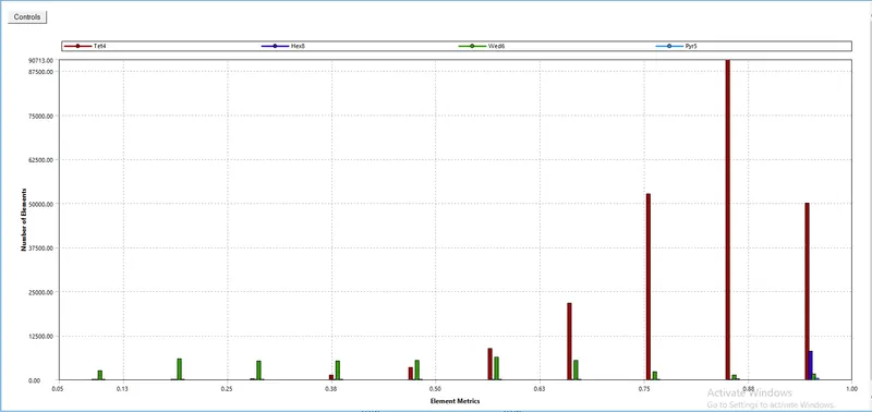
1. Naming the geometry as to inlet, outlet, carwall and symmetry.
2. Then using the multi-zone method for the outer encloser with an element size of 0.1m and max size 0.1m as well.
3. For the inner encloser use the body sizing of an element size of 0.03m.
4. Edge sizing is used for the bottom circles in the carwall with a number of divisions 40.
5. Then add inflation layer near the car-wall and choose 8 layers and provide total thickness of 0.048m.
6. Finally check for the mesh quality.
Solution and Results :
|
SETUP |
||
|
Solver Type |
pressure - Based |
|
|
Velocity Formulation |
Absolute |
|
|
Time |
|
|
|
Viscous Model |
K-epsilon | |
|
Material |
Fluid type: Air |
|
|
Cell zones ff_surface |
Fluid type: Air | |
|
Boundaries |
Inlet (velocity inlet) Velocity Magnitude 25m/s Temperature – standard Outlet x (Pressure outlet) Gauge Pressure – 0 pa. Wall - wall Symmetry - symmetry |
|
|
Reference values |
Area = 0.065741`m^2` Density = 1.225kg/`m^3` Enthalpy = 0 `J/(kg)` Pressure = 0 pa Temperature = 288.16K Velocity = 25m/s Viscoity = `1.7894e^(-5)``(kg)/(m.s)` Length of the ahmed body(L_c) = 1.044m |
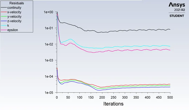
Residual plot :
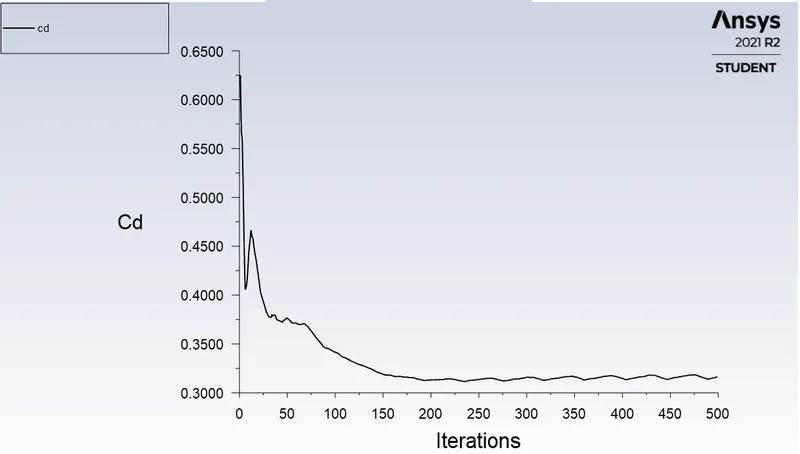
Drag co-efficient plot :
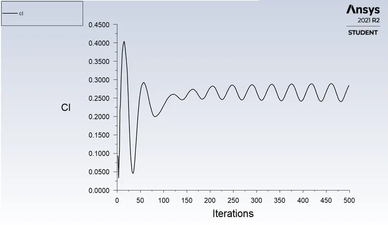
Lift co-efficient plot :
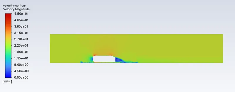
Velocity contour plot :
Pressure at the front side of the car :
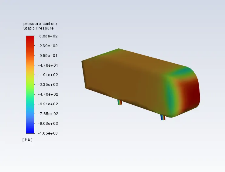
Pressure contour plot :

Velocity vector plot :
Velocity pathlines :
Comparison of all cases :
| Steady-state, Turbulent flow, pressure-based, Fluid material-Air | |||||
| Grid Independence Test | Number of elements | Type of mesh | No of inflation layers | Lift-Coefficient | Drag-Coefficient |
| Case 1 | 97315 | Coarse | 5 |
0.25447883 |
0.35703825 |
| Case 2 | 149725 | Medium | 7 | 0.25785185 | 0.33198788 |
| Case 3 | 277261 | Refined | 8 |
0.28653995 |
0.31662795 |
The standard reference of drag coefficient taken from W.Meile [2] is approx 0.3125. The resulting numerical solution is C_d = 0.3166, which is close agreement with the standard reference.
Numerical error :
| Cases | % Error |
| Case 1 | 14.25 |
| Case 2 | 6.24 |
| Case 3 | 1.32 |
Conclusion :
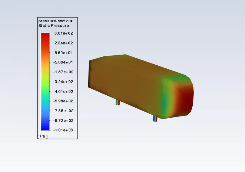
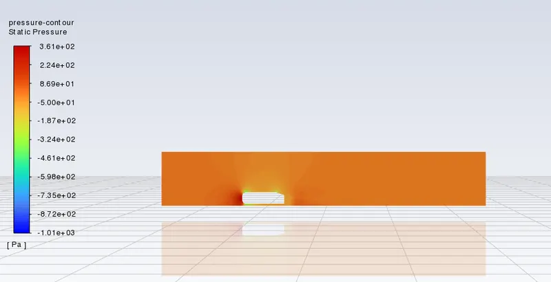
- High pressure is formed at the frontal area of the Ahmed body due to the loss of kinetic energy of the air.
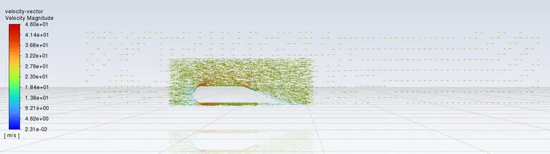
- When the airflow experiences sudden geometrical changes (slant length), it will start to detach from the surface of the body. This will subsequently lead to formation of eddies and region of recirculation immediate behind the body. It represents wake region which accounts for low pressure distribution behind the body causing imbalance in the net pressure distribution. The low pressure region will be obtained from flow separation due to adverse pressure gradients.This wake region holds the car body from behind and hence restricts the motion of the body which in turn affects the drag and lift coefficients .
- In order to reduce the size of the wake region, detachment of the fluid should be farther away from the body which can be achieved by an increase in the slant angle.
- With the increase in mesh size, the numerical results approach closer to experimental results.
References :
1. Some Salient Features of the Time -Averaged Ground Vehicle Wake.
https://flowvision.ru/images/articles/2020/Add_files/Ahmed_1984.pdf
2. Experiments and numerical simulations on the aerodynamics of the Ahmed body.
3. Flow and Turbulence Structures in the Wake of a Simplified Car Model.