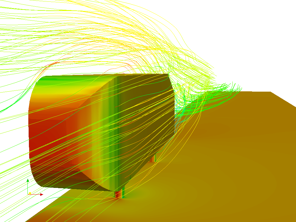
External flow simulation over an Ahmed body.
CFD Simulation of the Air Flow around a Car Model (Ahmed Body)
Importance of Ahmed body:
As the burning of fossil fuels becomes a more pressing issue, manufacturers are introducing more fuel efficient cars to the market. One main contributor to fuel burn is the car’s aerodynamic drag. Complexly shaped, cars are very challenging to model and it’s difficult to quantify the aerodynamic drag computationally. The Ahmed body is a benchmark model widely used in the automotive industry for validating simulation tools. The Ahmed body shape is simple enough to model, while maintaining car-like geometry features.
The drag coefficient quantifies the resistance of an object in a fluid environment. It is not an absolute constant for a body’s shape because it varies with the speed and direction of flow, object shape and size, and the density and viscosity of the fluid. The lower the drag coefficient of an object, the less aerodynamic or hydrodynamic drag occurs. In terms of a car, the lower the drag coefficient, the more efficient the car is. As well as affecting the top speed of a vehicle, the drag coefficient also affects the handling. Cars with a low drag coefficient are sought after, but decreasing the drag drastically can reduce the downforce and lead to loss in road traction and a higher chance of car accidents.
Most cars have an average drag coefficient of between 0.30 and 0.35. Boxy cars have a higher number, like the HUMMER® H2 vehicle at 0.57, while more streamlined and agile cars have a lower number, like the Mercedes-Benz® C-Class® vehicle at 0.24. Again, this is just an average measurement. The exact drag coefficient of a car varies with the Reynolds number and various other factors.
There are certain ways to modify a car to optimize its aerodynamics and decrease the drag coefficient. To streamline the exterior, you can remove certain aftermarket items such as the roof rack, mud flaps, spoilers, and radio antenna. Professional car racers also take off their windshield wipers and side mirrors, but this isn’t recommended for the average driver! You can also add wheel covers, a partial grille block, an under tray, fender skirts, and a modified front bumper to improve the drag coefficient and make your car stand out in the process.
The Ahmed body is a generic car body (a simplified vehicle model). The airflow around the Ahmed body captures the essential flow features around an automobile and was first defined and characterized in the experimental work of Ahmed [1]. Although it has a very simple shape, Ahmed body allows us to capture characteristic features that are relevant to bodies in the automobile industry.
This model is also used to describe the turbulent flow field around a car-like geometry. Once the numerical model in validated, it is used to design new models of the car.
The aim of the "Models for Vehicle Aerodynamics" (MOVA) Project is to develop, refine, and validate the latest generation of turbulence models for selected examples encountered in vehicle aerodynamics. The validation of turbulence models requires the availability of detailed experimental data. These quantitative data should cover the most critical flow regions around a bluff car-shaped body and they should give physical quantities that can directly be correlated to the results of numerical simulations. Such experimental data were measured in the LSTM low speed wind tunnel using a 2-component laser-Doppler anemometer (LDA) mounted on a traversing system and a simplified model of a car (Ahmed model). Measurements were made for two rear vehicle body slant angles (25° and 35°) at a bulk air velocity of 40 m/s
AIM:
To simulate flow over ahmed body & to address the below given tasks.
1. Describe Ahmed body & its importance.
2. Explain the negative pressure in wake.
3. Explain significance of the point of seperation.
Expected results:
1. Velocity & pressure contour of the Ahmed body.
2. Cd for a refined case. (for velocity = 25m/s, Cd = 0.33)
3. Vector plot must show wake region.
4. With grid dependency test provide Cd & Cl for each case.
Note:
1. Since the ahmed body is symmetric, run the simulatoion by considering only half body. Doing this would increase the cell count and would make the mesh finer.
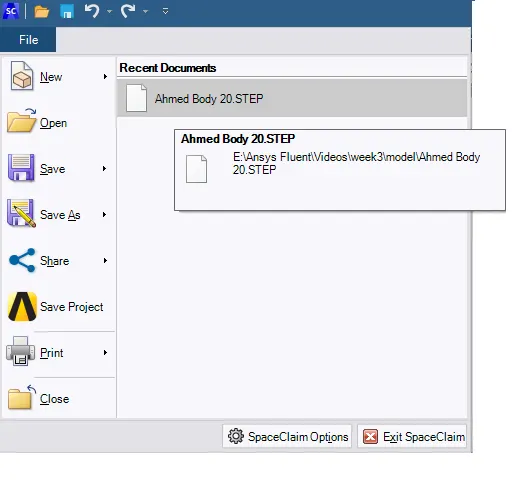
2. Use split body command in spaceclaim & use symmetry boundary condition.
3. Maintaining an appropriate y+ value will give correct Cd value.
Geometry:
Car Model Geometry:
Figure shows the layout of the geometry provided in the assignment cover sheet for Ahmed Body Car with a slant angle ϕ equals to 40°. From the figure below, the horizontal length covered by the slant (L) and its height (H) can be
calculated as follow:
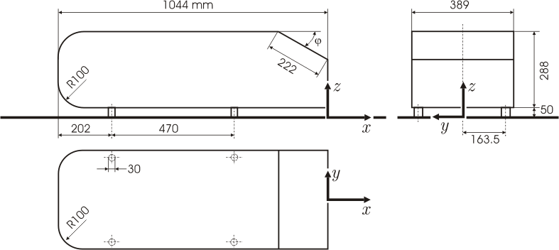
Layout of Ahmed Body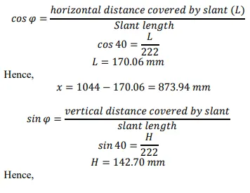
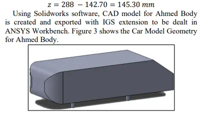
Ahmed Car Body CAD Mode
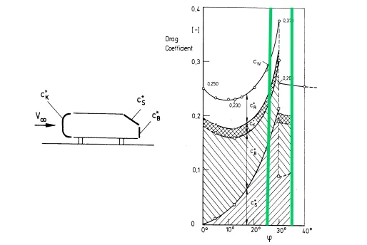
Characteristic drag coefficients for the Ahmed body for various slant angles.
References
https://www.researchgate.net/publication/330383775
https://www.researchgate.net/publication/266883948
http://www.ijsrp.org/research-paper-0718/ijsrp-p7979.pdf
simulation over an Ahmed body
SET UP:-
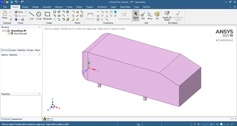
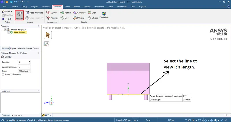
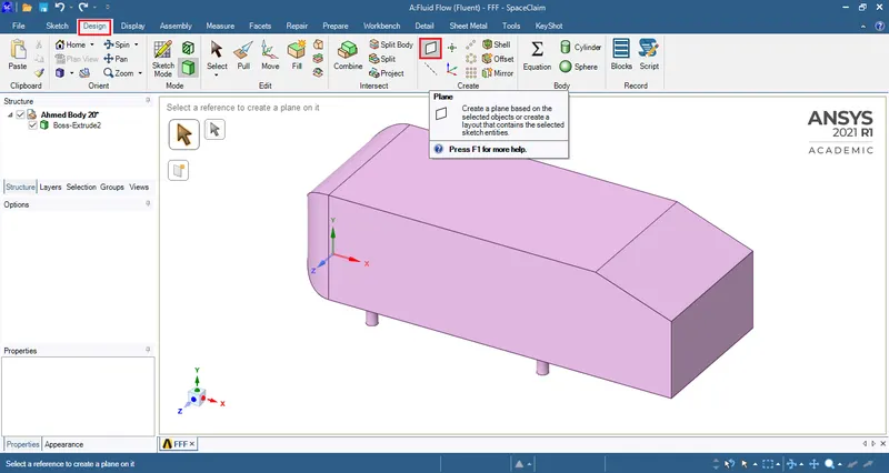
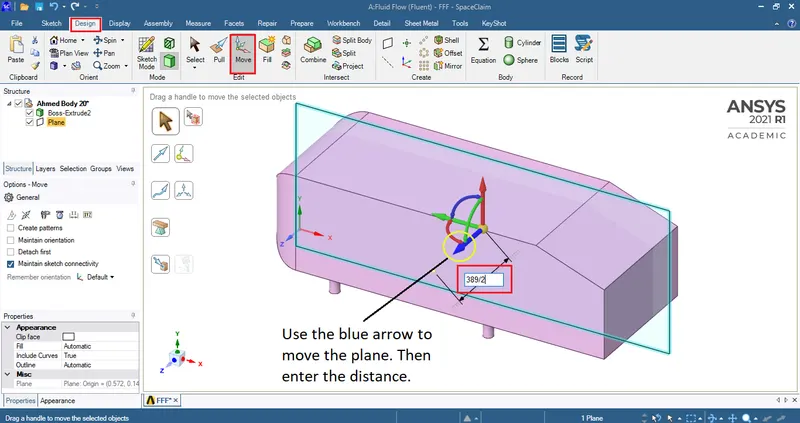
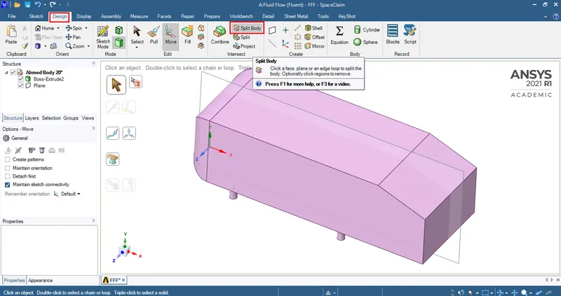
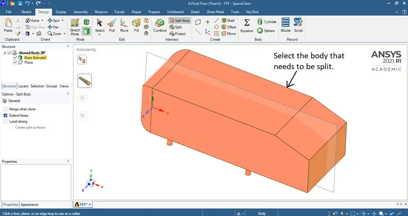
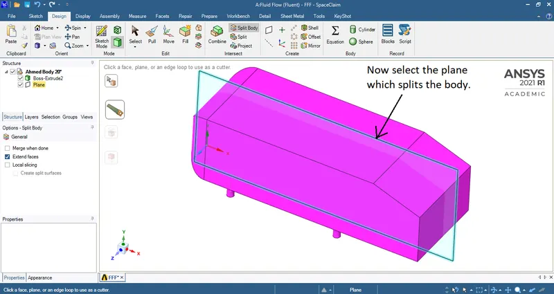
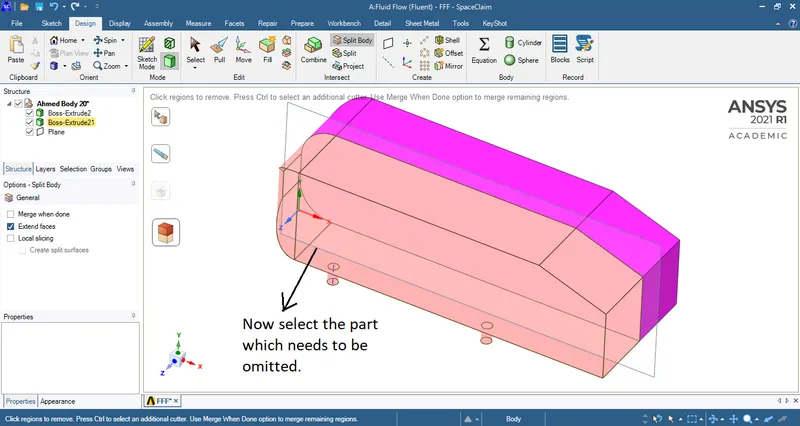
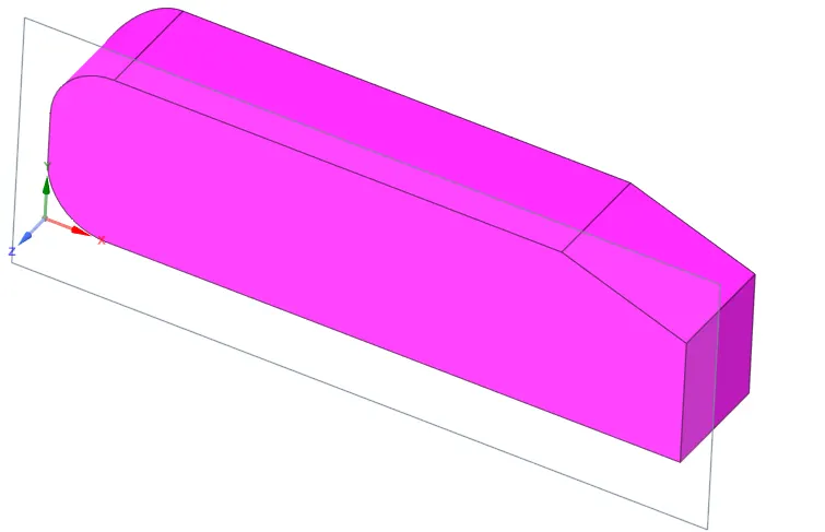
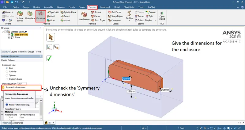
Side view:
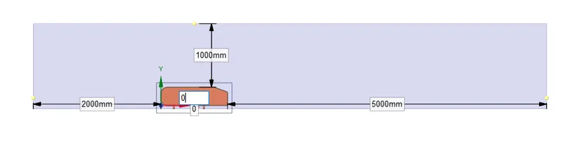
Top view:
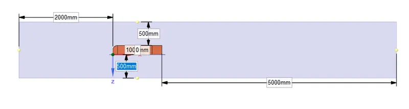
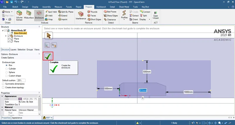
To finish click the green tick.
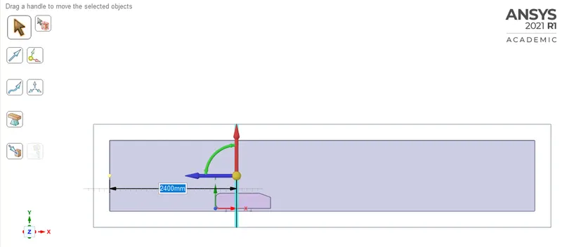
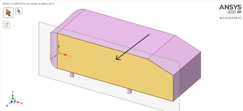
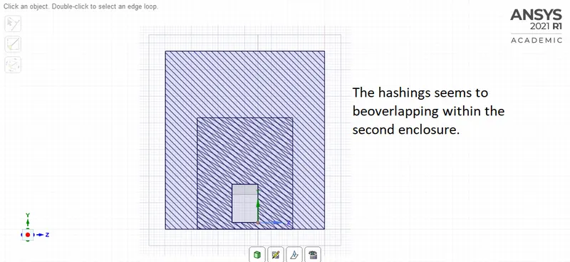
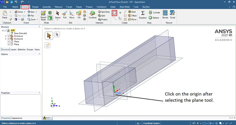
Creating a plane to view material hashing in the cross sectional view.
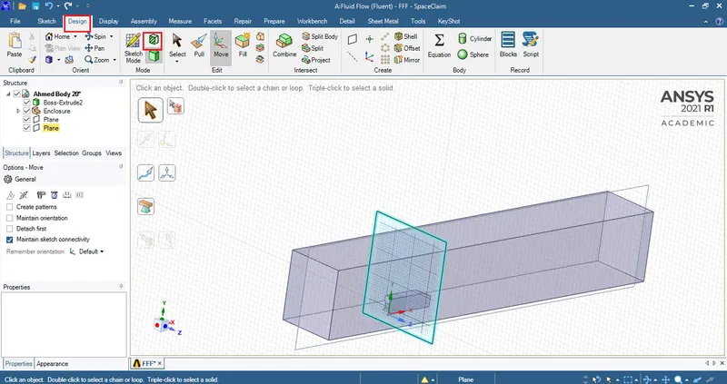
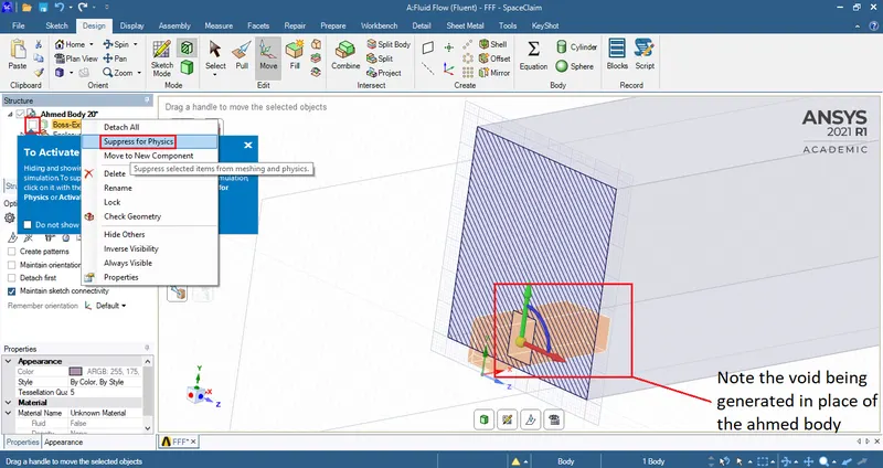
Since the domain around the 'Ahmed body' is required for simulation the inner hashing has to be hidden by unchecking it from under the 'Structure' on the left hand side.
In addition to this the 'Ahmed body' has to be excluded during simulation and hence must use 'supress for physics' option.
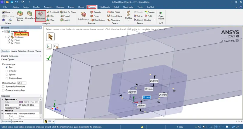
Enter the dimensions for the newly formed enclosure.
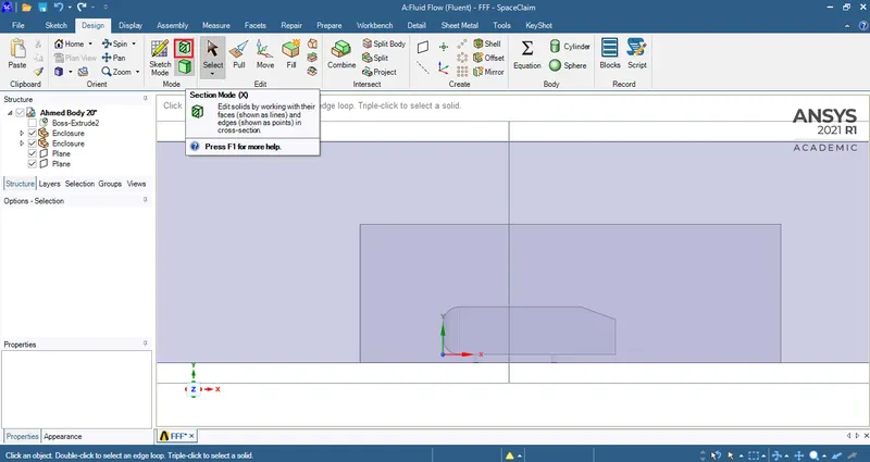
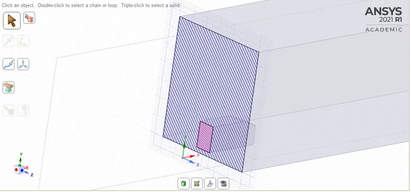
After selecting the Selection mode hit on the plane to view the hashings.
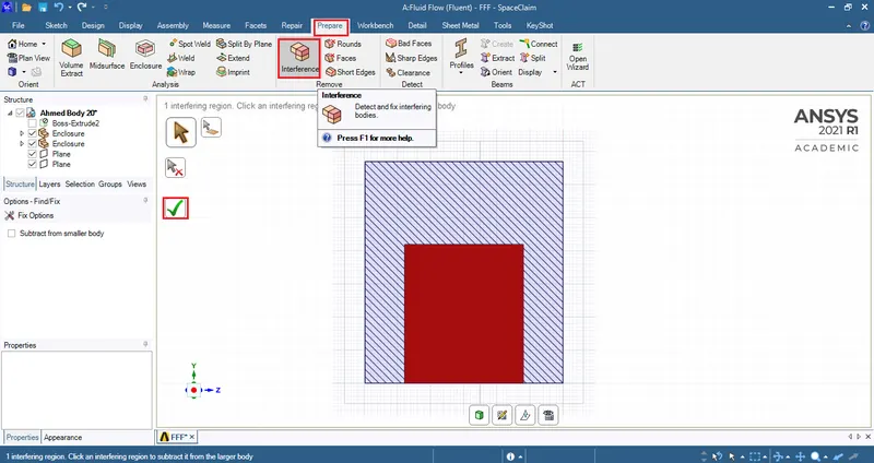
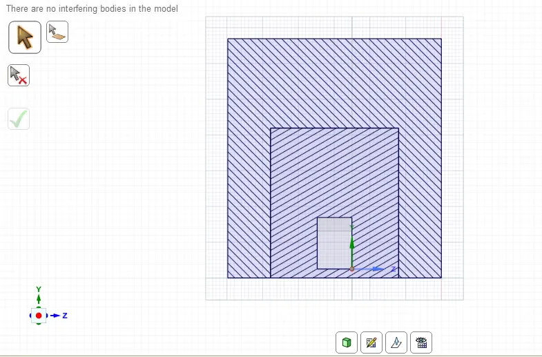
When the green tick mark is clicked, the interferanceissue will be solved resulting in a clear distinction between the hashings of different enclosures.
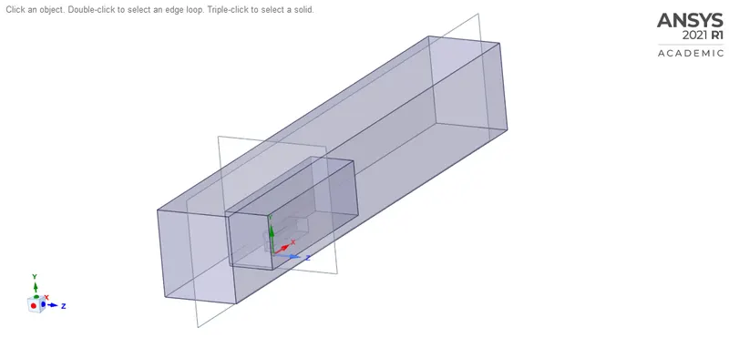
Error!
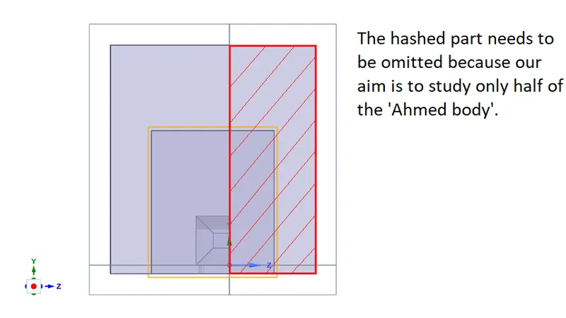
Here the 'Ahmed body' which is symmetrical from nose to tail has been cut up in half to generate finer cells. Since only half of the body will be analysed the number of large sized cells required will reduce and the number of small and fine cells increases.
The issue at hand now is the enclosure has been created for the whole body.
The corrective measure to this issue would be to split and delete the excess enclosures.
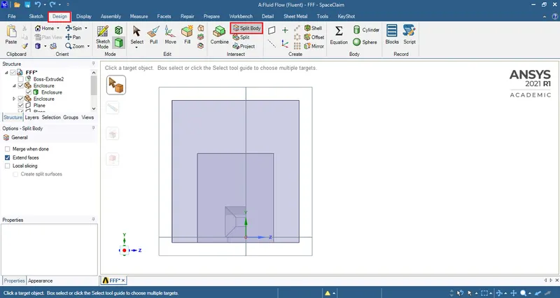
Body split command can be used to delete the excess enclosure.
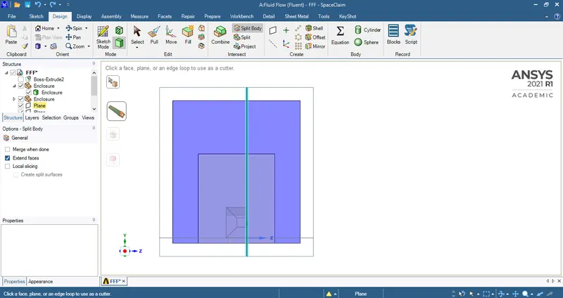
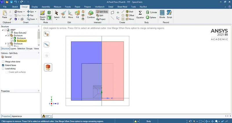
Follow the same steps to delete the excess from the inner enclosure.
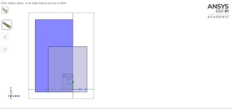
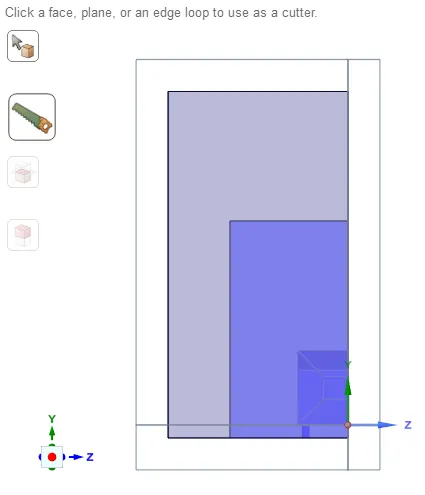
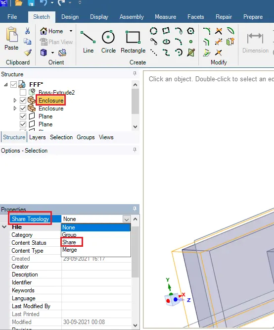
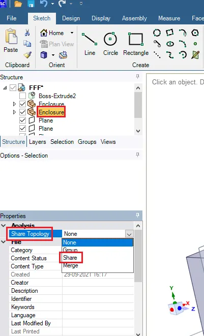
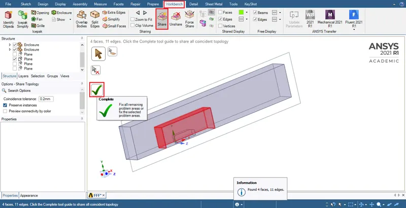
This ensures that information exchange happens between the 2 enclosures.
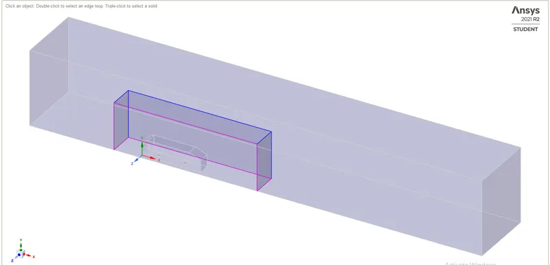
GENERATING MESHING:-
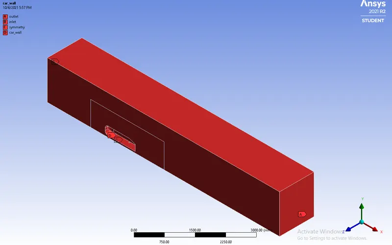
Naming the inlet,outlet , symmetry and car wall faces
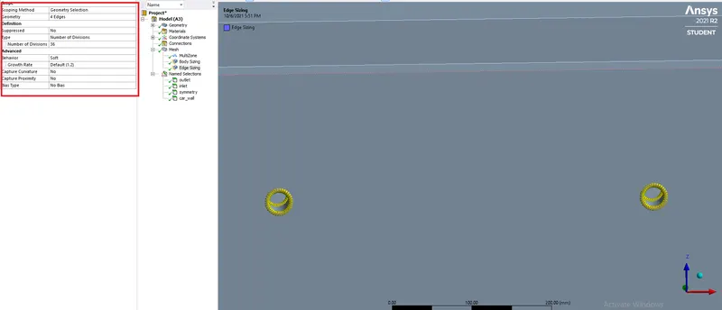
For legs of the ahmed body we are giving 36 divisions so that the mesh will be fine on the legs
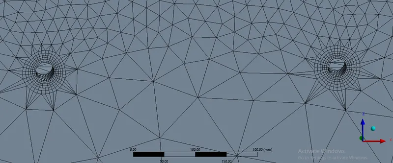
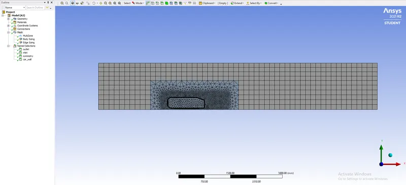
here we are using 2 enclosers
for outer encloser we are using the hexa mesh and tetras for the inner encloser
SET UP:-
Start with checking the mesh.
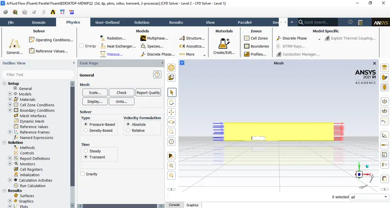
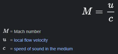
Since the velocity has been decided to be 25m/s and the speed of sound at sea level is 340.197m/s.
Then the mach number would be 25(ms)340.197(ms)=0.07349">25(ms)340.197(ms)=0.0734925(ms)340.197(ms)=0.07349.
Since the mach number is lesser than 0.3, hence a pressure based solver must be used.
If the mach number is greater than 0.3 then the density based solver must be chosen.
For time accurate results a transient or unsteady simulation must be selected.
Perform check mesh to see if the mesh is ready to be used for simuation.
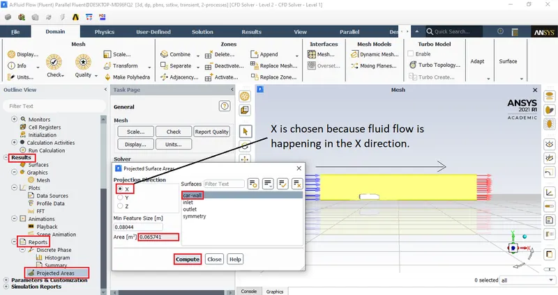
Projected area:
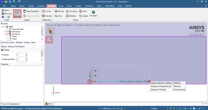
Characteristic length:
Since the focus here is to find the drag coeffecient of the 'Ahmed body' k-epsilon model can be chosen because this viscous model gives better results for large
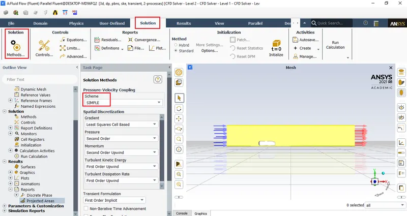
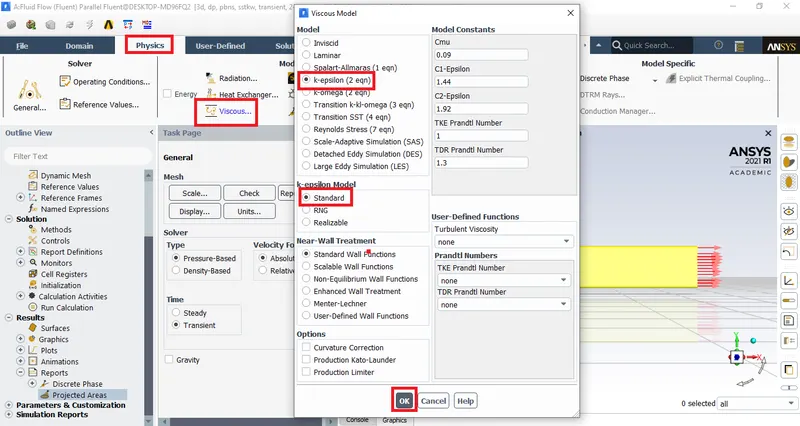
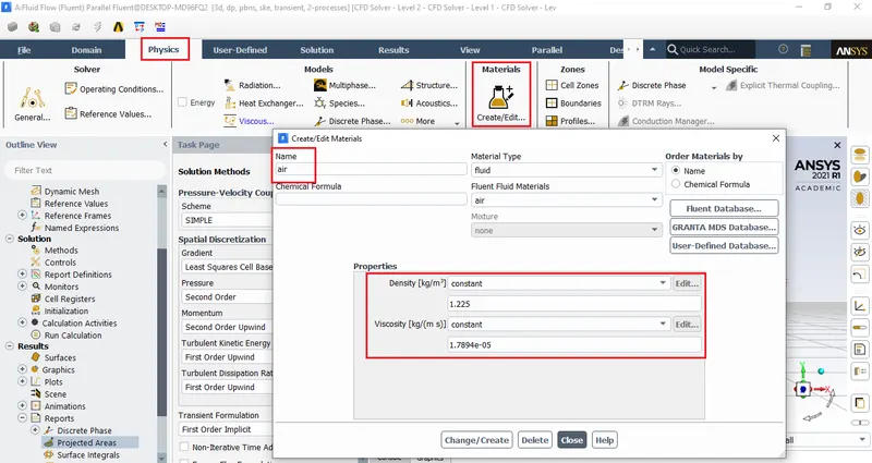
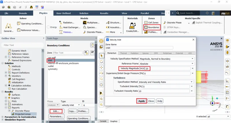
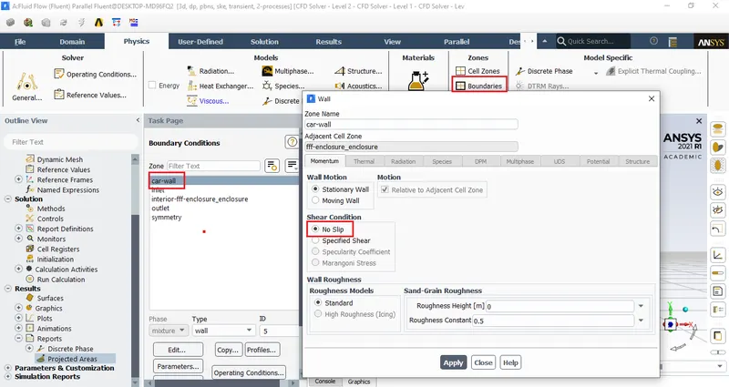

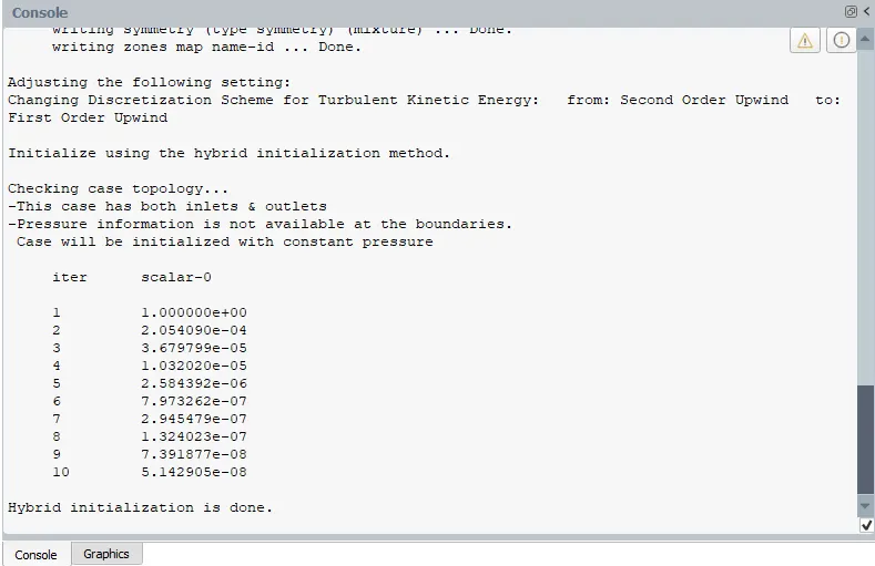
The idea is to solve for potential flow variables to get an estimate for the velocity components.
Here a value for pressure isn't possible but only the value for velocity is possible.
This provides a very good initial condition/starting point.
It's not an accurate approximation, it's a very good starting point when the flow path is really complex.
A PDE is obtained when you need to solve iteratively that's what happens when the solution is 'initialized'.
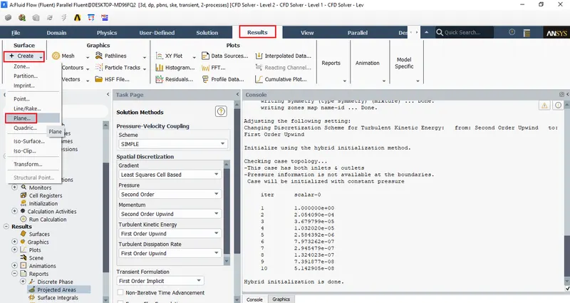
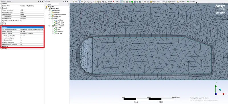
We are doing the grid dependent for three Y+ values 200,150 and 100 where the wall spacing(first layer thickenss) is 2.865 ,2.149 and 1.432 respectivly for the length of the domine 1.044 meters fluid as air
case 1 :- y+ = 200 first layer thickenss 2.865
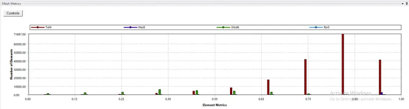
Mesh metrics
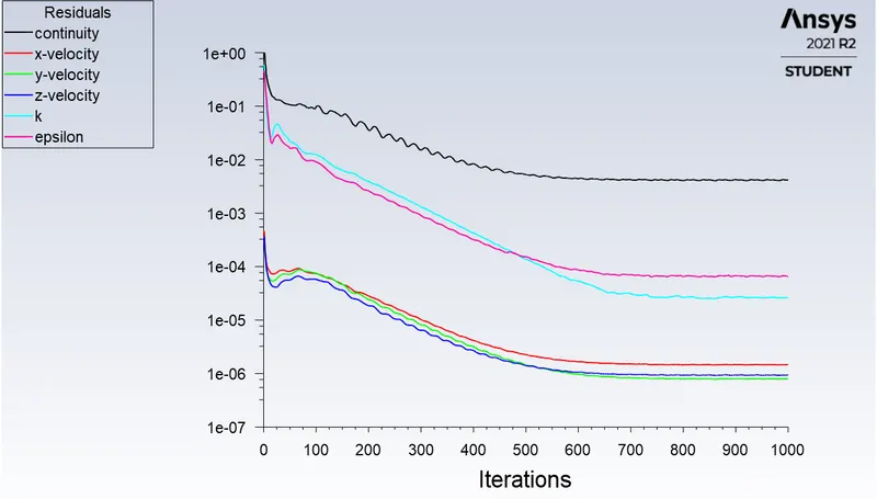
Residuals
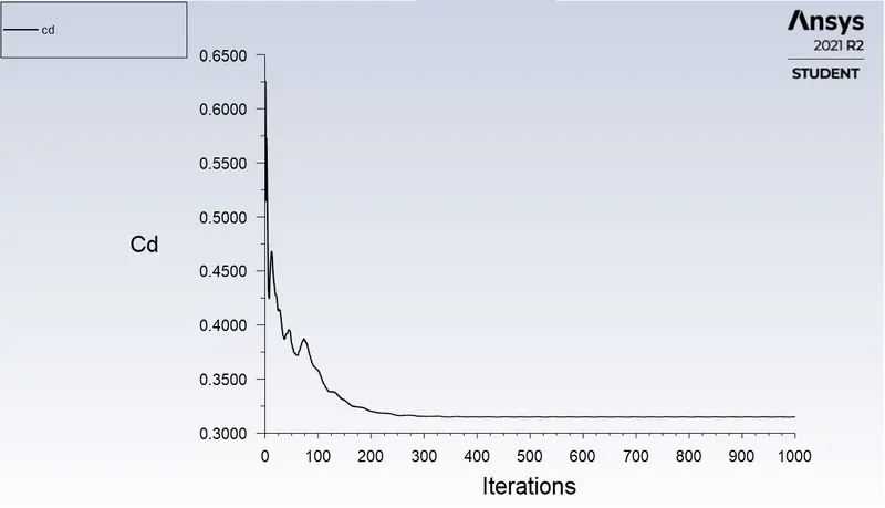
Drag coefficient
cd(Drag coefficient) = 0.314822
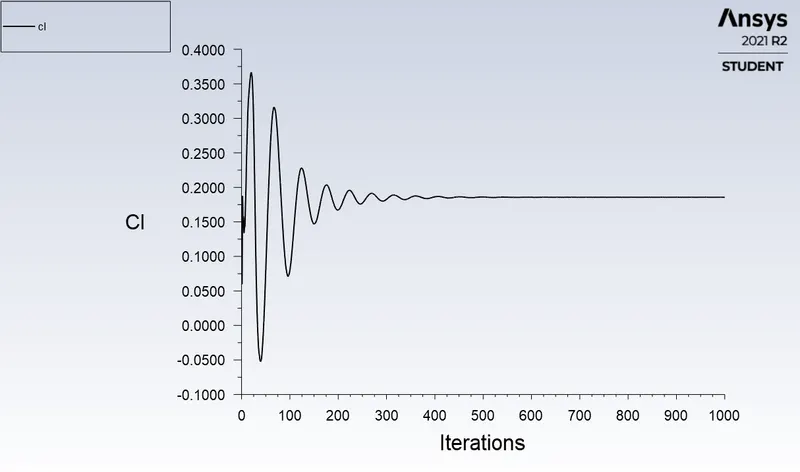
Lift coefficient
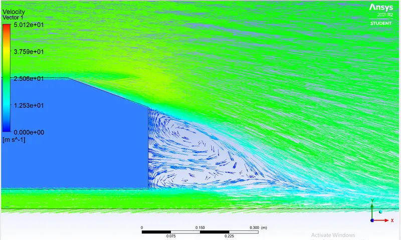
Velocity vector plot for the transverse plane (XY plane)
Velocity vector plots for 2 different transverse planes created at different positions (YZ plane)
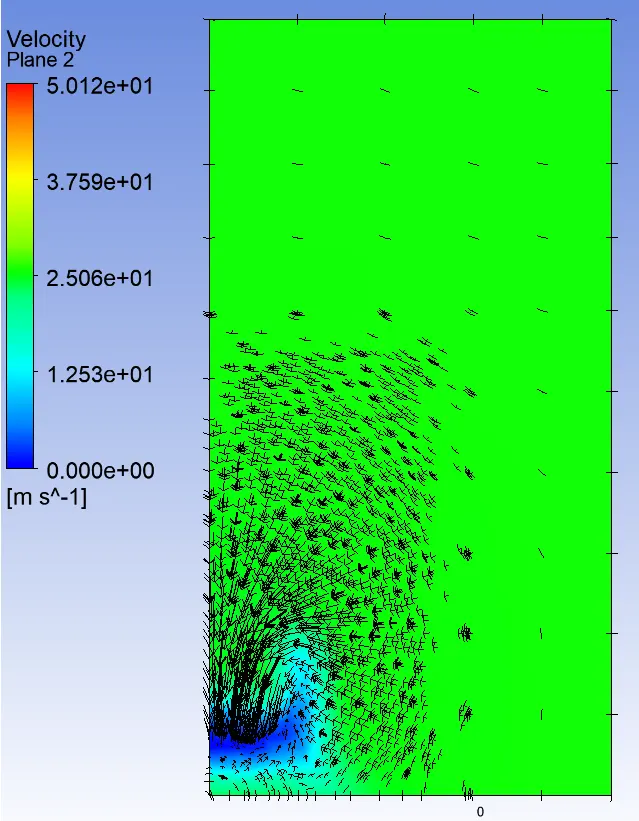
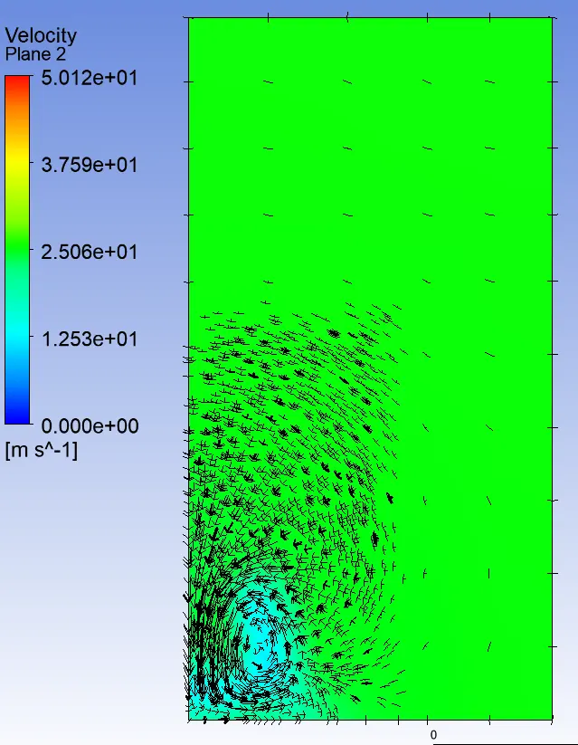
0.3 m from the body 0.5 m from the body
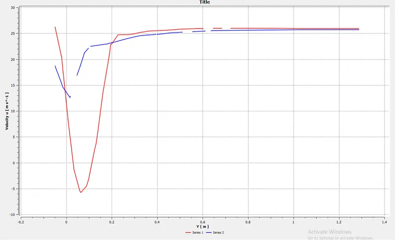
Velocity distribution plot for 2 different probes located at the 0.3 m and 0.5 m from the body
case 2 :- y+ = 150 first layer thickenss 2.149
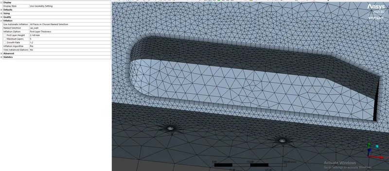
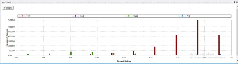
Mesh metrics
Residuals of the simultion are converged as we can see
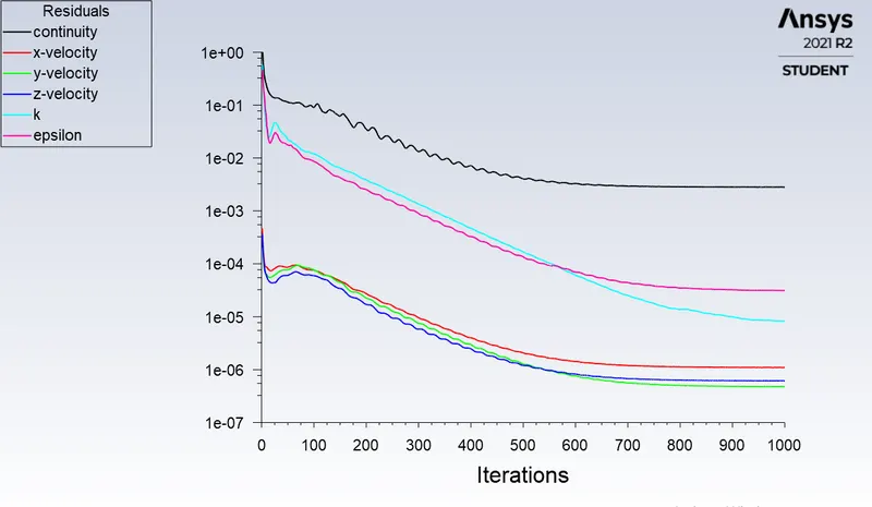
Residuals
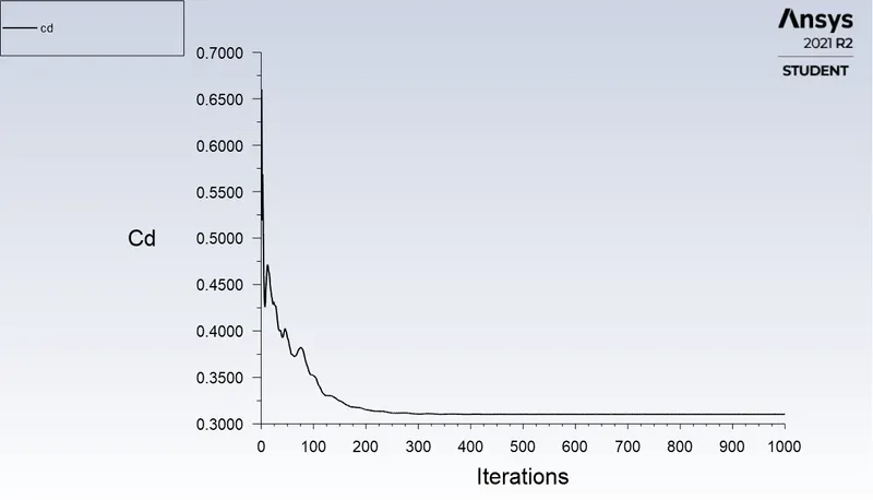
Drag coefficient
cd(Drag coefficient) = 0.310366
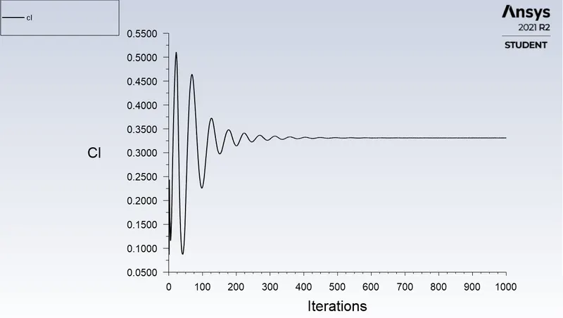
Lift coefficient
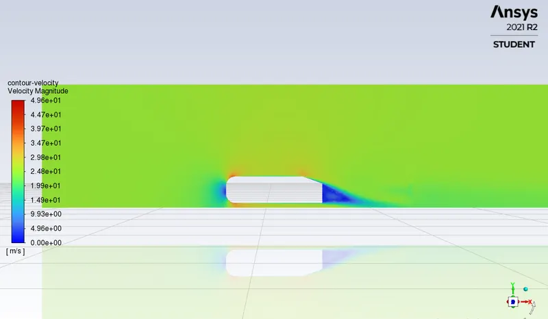
Velocity vector plot for the transverse plane (XY plane)
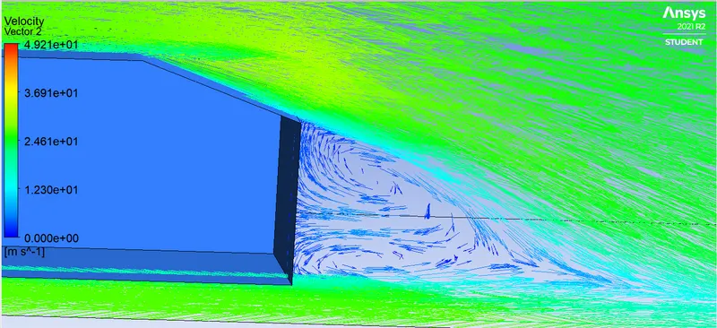
Velocity vector plots for 2 different transverse planes created at different positions (YZ plane)
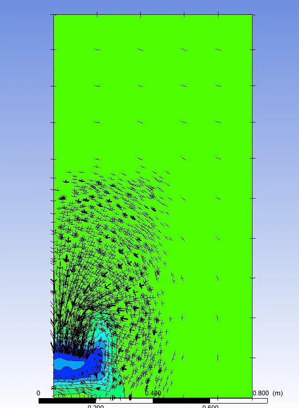
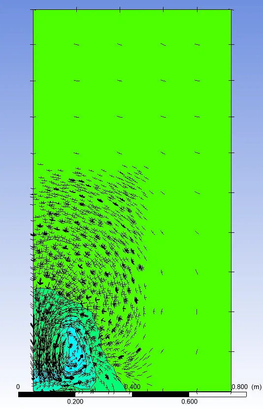
0.3 m from the body 0.5 m from the body
Velocity distribution plot for 2 different probes located at the 0.3 m and 0.5 m from the body
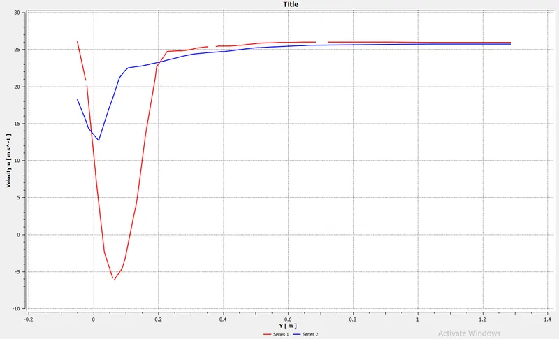
case 3 :- y+ = 100 first layer thickenss 1.432
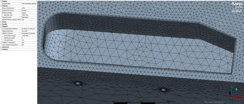
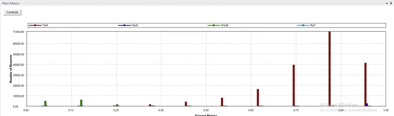
Mesh metrics
Residuals of the simultion are converged as we can see
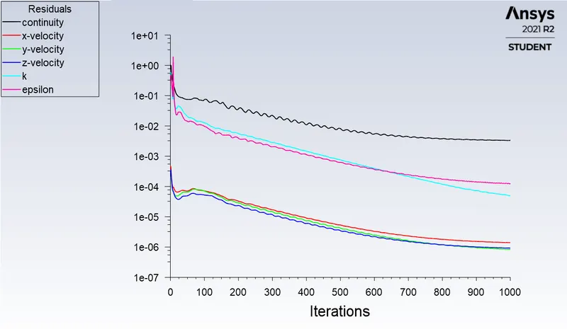
Residuals
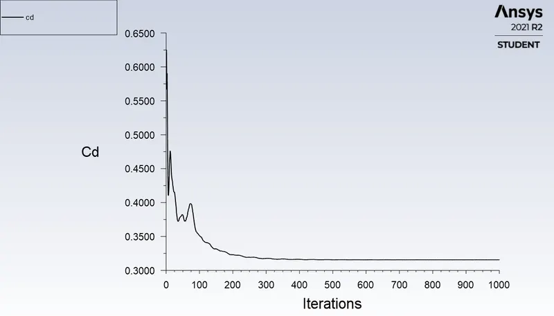
Drag coefficient
cd(Drag coefficient) = 0.310366
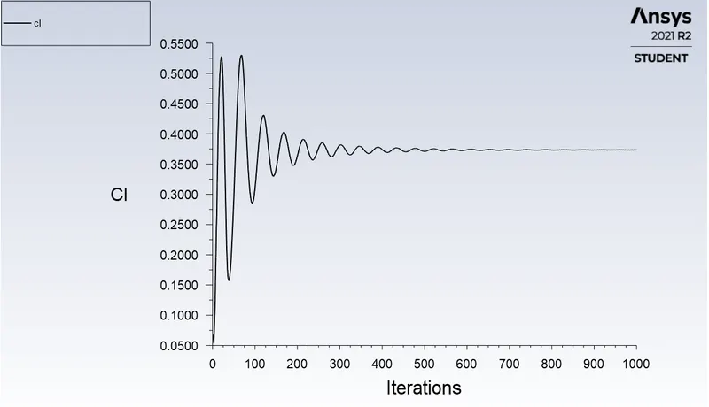
Lift coefficient
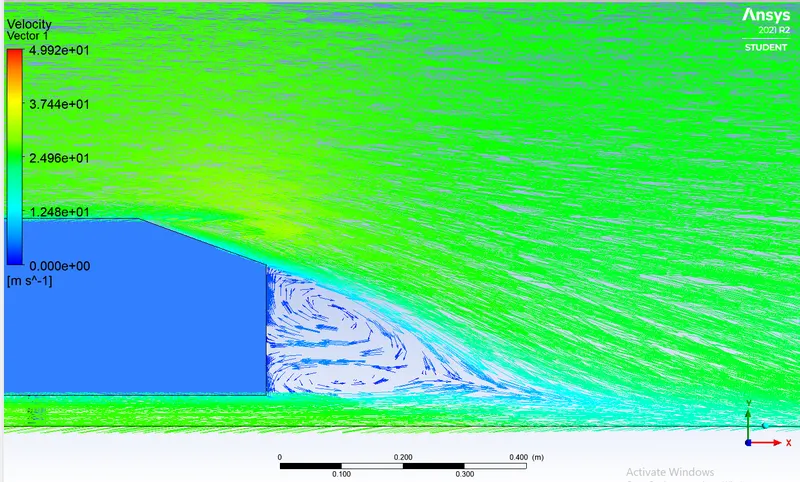
Velocity vector plot for the transverse plane (XY plane)
Velocity vector plots for 2 different transverse planes created at different positions (YZ plane)
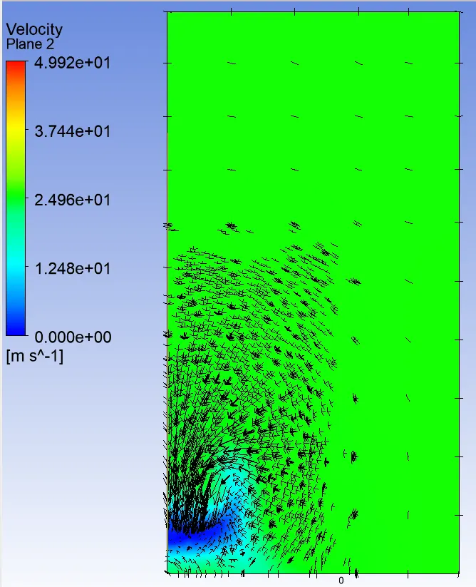
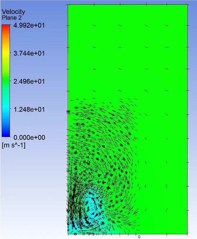
0.3 m from the body 0.5 m from the body
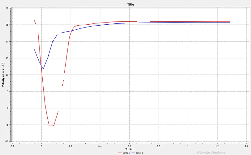
Velocity distribution plot for 2 different probes located at the 0.3 m and 0.5 m from the body
RESULTS:-
| Y+ | First layer thickenss (`Deltas`) | Nodes | Elements | Lift coefficient (cl) | Drag coefficient(cd) | Error % of cd to given cd = 0.33 |
| 200 | 2.865 | 49585 | 212005 | 0.18559 | 0.31482 | 4.5 % |
| 150 | 2.149 | 50431 | 216790 | 0.33091 | 0.31033 | 5.9 % |
| 100 | 1.432 | 41957 | 196210 |
0.3731 |
0.31522 |
4.47% |
Wake Structure
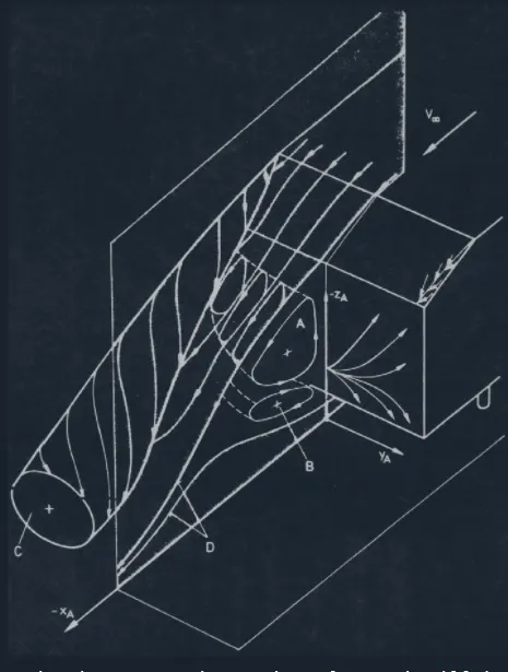
Another important goal of this study is examining the wake structure. In the original paper from S.R.Ahmed, the authors observed that the wake flow exhibits a triple deck system of horseshoe vortices. The strength, existence, and merging of these vortices depend upon the base slant angle. In a time-averaged sense, the regions of flow separation exhibit complex kinematic macro structures. Such structures in the wake, which is the major separated flow region of a vehicle flow field, determine the drag experienced by the body. The shear layer, coming off the slant side edge, rolls up into a longitudinal vortex, in a manner similar to that observed on the side edge of low aspect ratio wings. At the top and bottom edges of the flat vertical base, the shear layer rolls up as indicated, into two recirculatory flow regions A and B, situated one over another. As the flow over the slant surface is influenced by the vortex C coming off the side edge, the strength of vortex A is dependent upon the strength of vortex C. The flow observation described in [1] was clearly confirmed with the TCFDsimulation.
Reason for the negative pressure in the wake region:
The reason for negative pressure in wake region is due to formation of vortices. These vortices are localised zones of low pressure that decelerate a body in motion.
This is called the region of recirculation which is caused by the viscosity of the fluid.
The negative pressure in the wake region behind the Ahmed Body is a result of dominance of pressure and viscous forces over the accelearating force of fluid. Pressure in the wake remains close to separation-point-pressure since the eddies cannot convert rotational kinetic energy into pressure head.
Point of seperation & its significance:
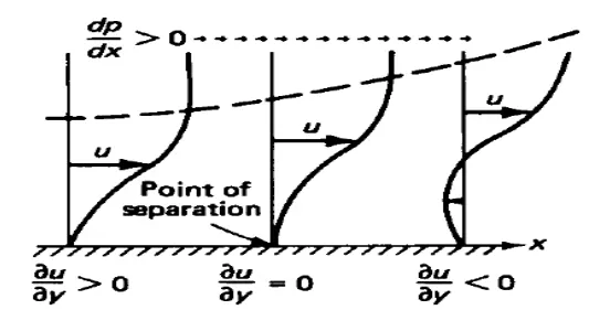
Separation of flow is said to occur when the direction of the flow velocity near the surface is opposed to the direction of the free stream velocity, which means (du/dy) ≤ 0. Such a situation arises when there is a negative pressure gradient near the wall (Refer figure below). An example is subsonic diffuser or rear portion of the car. In the direction of flow the pressure increases which causes decreases in velocity and creates condition for separation to occur.
It is important to note that, the skin-friction coefficient reaches the value zero. At this point the wall shear stress vanishes is called the separation point. Reverse flow takes place beyond point of separation. Due to reverse flow, irregular eddies are formed and lot of energy is dissipated. This region is called "Wake". The pressure distribution in the wake is quite different from that on the remaining boundary and this gives rise to an additional drag force on the body. Wake also leads to lateral vibration to the object which may be harmful. Also large amount of K.E. is lost.
In the turbulent boundary layer, some of the energy is dissipated in friction, slowing airflow velocity, resulting in a pressure increase. If the increase in pressure is gradual, the process of turbulent mixing will cause a transfer of energy from the fast moving eddies to slower ones in the turbulent boundary layer. If the rate of change in pressure is too great, for example in sharp corners, the mixing process will be too slow to push the slower air molecules moving. When this happens, the boundary layer flow stops following the contours of the surface, resulting in separation. Air particles downstream of the separation region will then move towards the lower pressure region in the reverse direction to the main flow, the separation region will reattach. In the region between separation and reattachment points, air flow is circulating and this is called the "separation bubble"