Week 3 - External flow simulation over an Ahmed body.
Aim
To simulate the flow over an ahmed body
Expected Results:
1. Velocity and pressure contours.
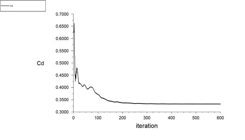
2. The drag coefficient plot for a refined case. ( For velocity of 25m/sec, the drag coefficient should be around 0.33).
3. The vector plot clearly showing the wake region.
4. Perform the grid independency test and provide the values of drag and lift with each case.
Ahmed body and its Importance
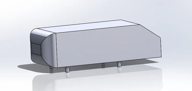
Ahmed's body is a generic form of the car body that resembles all the essential flow features around a vehicle. This generic form was first defined and characterized in the experimental work of S.R.Ahmed. This body allows us to capture all the characteristics features that are relevant to bodies in the vehicle industry. This body can be used for a lot of experiments like calculating the drag and lift which are essential nowadays in the design of car bodies. Also this can be used to capture the wake regions, Flow seperation, vortices etc.. Different slant angles provide different values for Coeffecient of drag.
The reason for the negative pressure in the wake region
Wake region is formed behind the ahmed body as a result of viscous forces.The layer over the ahmed body get detatched at the rear end and a wake region is created. The velocity gradient is negetive here and the shear stresses in the flow creates a turbulent flow in wake region As the velocity of flow near to wall is almost zero due to no-slip condition the flow near to boundary layer end up in the rear side of the body through top and lower part of the body a region of low pressure relative to the pressure just outside the wake region, since there is a low pressure, the fluid has to work against adverse pressure gradient
Significance of point of seperation
The flow seperation takes place where the dv/dx or velocity gradient is zero along with pressure gradient along x-axis = 0 for the specific point.The flow seperation can be detected by a single contour and it can also be detected by ploting the velocity aliong y-axis at that region.
Flow separation or boundary layer separation is the detachment of a boundary layer from a surface into a wake. Separation occurs in flow that is slowing down, with pressure increasing, after passing the thickest part of a streamline body or passing through a widening passage, for example.
Flowing against an increasing pressure is known as flowing in anadverse pressure gradient. The boundary layer separates when it has travelled far enough in an adverse pressure gradient that the speed of the boundary layer relative to the surface has stopped and reversed direction. The flow becomes detached from the surface, and instead takes the forms of eddies and vortces. The fluid exerts a constant pressure on the surface once it has separated instead of a continually increasing pressure if still attached.In aerodynamics, flow separation results in reduced lift and increased aerodynamic, caused by the pressure differential between the front and rear surfaces of the object.
Since after the separation point the flow no longer adheres the surface of the body, the skin friction drag is almost zero. At the same time, however, the pressure drops considerably due to the energy dissipation in the turbulent wake. This leads to a significant increase in pressure drag, which is far greater than the reduction in skin friction drag. In total, the parasitic drag (air resistance) thus increases very strongly in the event of a flow separation.
Y+
It is important to refine our mesh wherever the changes in physics is expected to take place, so it is important to refine our mesh near the wall of the ahmed body.Y+ Is a dimensionless number which is used to determine how coarse our cell should be near the boundary so that it can capture the physics near the wall , Here we basically choose our desired y+ and then the first layer thickness is found using the following equations
Free stream velocity = 25m/s
Density = 1.225 kg/m^3
Dynamic viscosity = 1.7894e-4 kg/ms
Length = 1.044 m
Re = `(rhovd)/(mu)` = (1.225*25*1.044/1.7894e-5) = 1.8e6
Friction coeffecient for external flows = 0.0576 Re^-0.2
Friction coefficient for internal flows 0.079 Re^-0.25
Here since this simulation is considered as a external flow the equation for friction coefficient is also selected accordingly
`C_f`= 0.0576*(1.8e6)^0.2 = 0.0032312308
`tau = 1/2(C_f)(rho)(u^2)` = 0.5*0.0032312308*1.225*25^2 = 1.236955479
so the ffrictional velocity becomes
`U_t=root2(tau_w/rho` = 1.236955479/1.225 = 1.0048679639634
v = `mu/rho` = 1.7894e-05)/(1.225) = 1.4607e-05
y = `v*Y^+/mu_t` = (1.4607e-05/1.0056)*`Y^+`
| Y+ value | First layer thickness |
| 50 | 0.7102 mm |
| 75 | 1.074725 mm |
| 100 | 1.4329665 mm |
Geometry
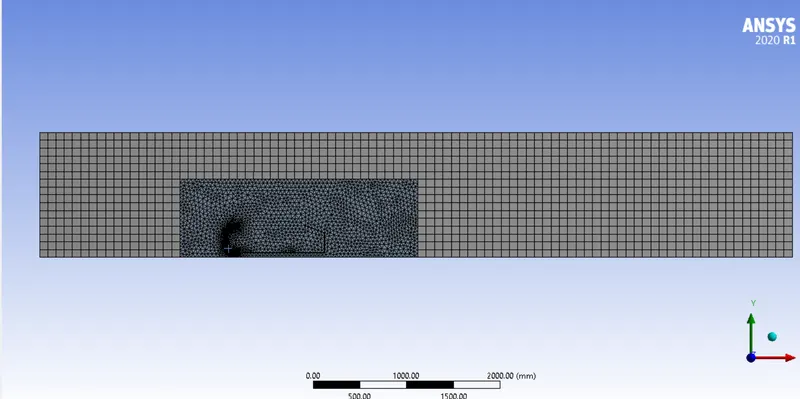
- A wind tunnel is created using enclosure option in space claim
- Enclosure option is used again inorder to refine the mesh further near the Ahmed body to capture the physics more effectively
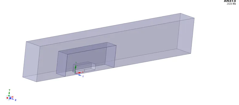
- Inorder to reduce the number of cells involved in the calculation the split option is used , where it cut into half and the one half is removed since we only need this part for the calculation
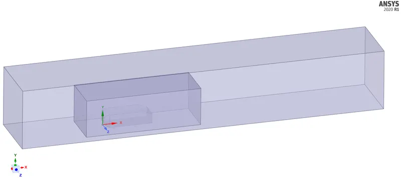
After using split option
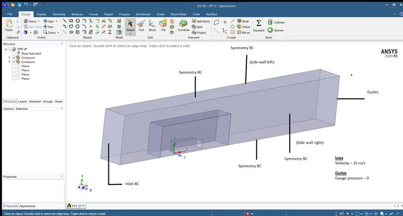
Boundary Conditions
Mesh
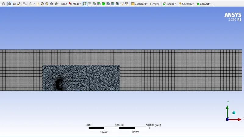
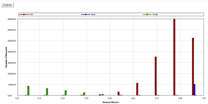
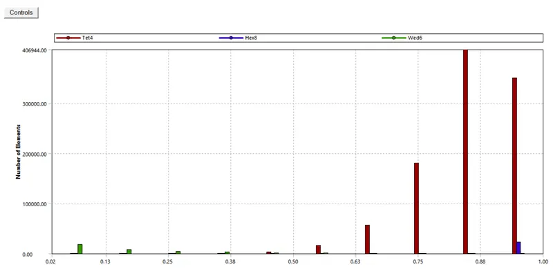
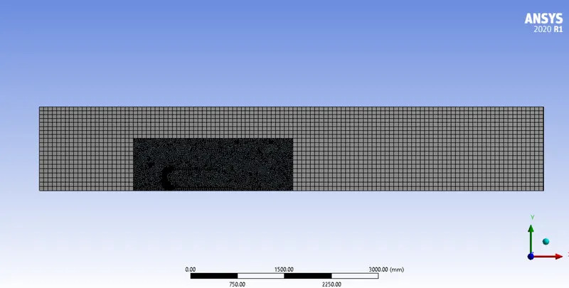
Case 1- (Mesh size of Outer enclosure = 100mm and inner enclosure = 50 mm)
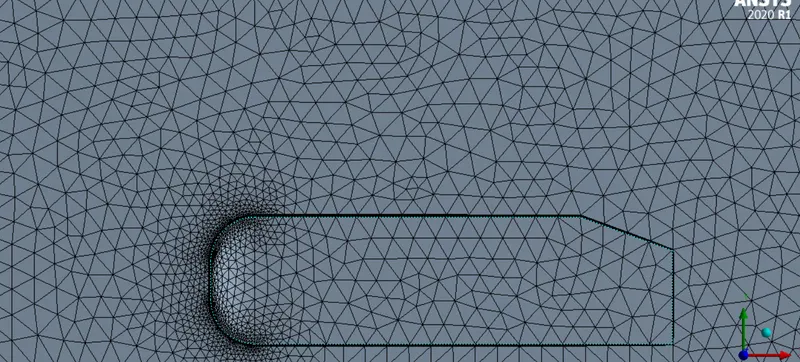
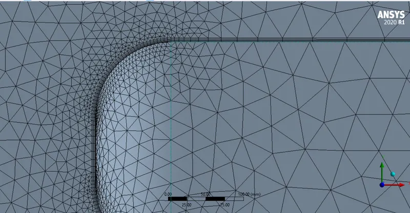
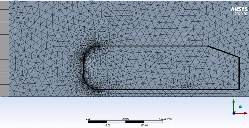
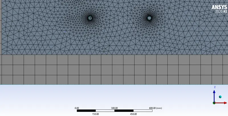
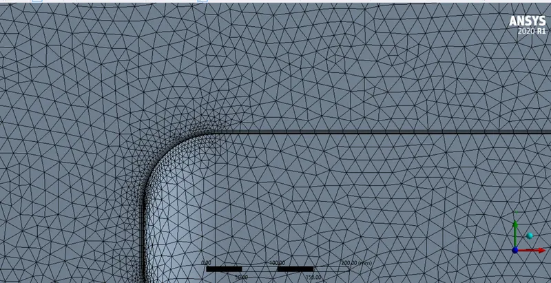
- I have set the number of divisions on the curved edges of ahmed body at the front to 35 and the number of division on the leg (cylinder part) to 30
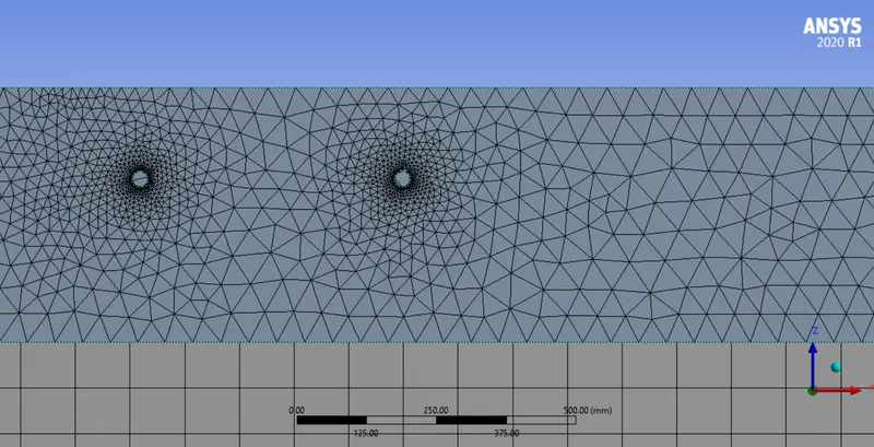
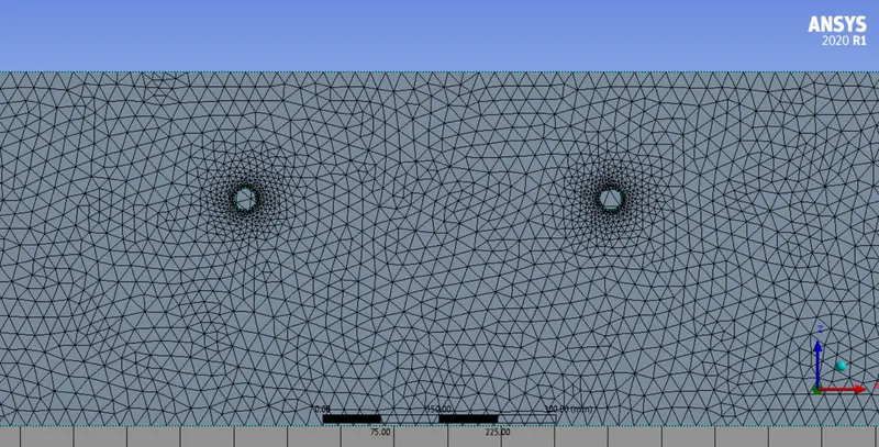
- Meshing is done on the first enclosure(wind tunnel) with multizone (hexahedral) mesh with a size of 100 mm and the 2nd enclosure mesh size is set to 50mm
- Also named selection is done on geometry as Inlet , outlet , symmetry walls and the part where the geometry is cut is named as symmetry (for reading it as symmetry boundary condition in fluent)
- Inflation is given to the car walls with a value that is found from Y+, I have chosen first layer thickness with 5 layers of 20% growth rate. The value of first layer thickness is listed below in accordance with the desired y+ values
Case 2- (Mesh size of Outer enclosure = 90mm and inner enclosure = 40 mm)
- Meshing is done on the first enclosure(wind tunnel) with multizone (hexahedral) mesh with a size of 90 mm and the 2nd enclosure mesh size is set to 40mm
- All the other settings is set to same as the first case
Case 3- (Mesh size of Outer enclosure = 80mm and inner enclosure = 30 mm)
- Meshing is done on the first enclosure(wind tunnel) with multizone (hexahedral) mesh with a size of 90 mm and the 2nd enclosure mesh size is set to 40mm
- All the other settings is set to same as the first case
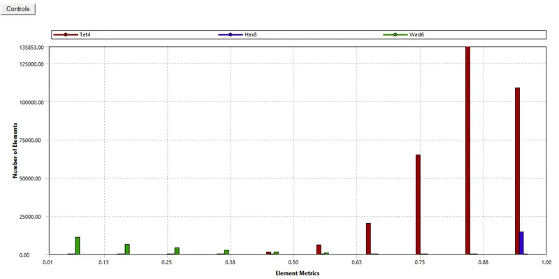
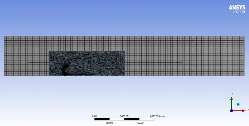
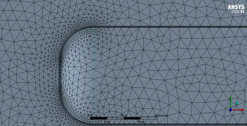
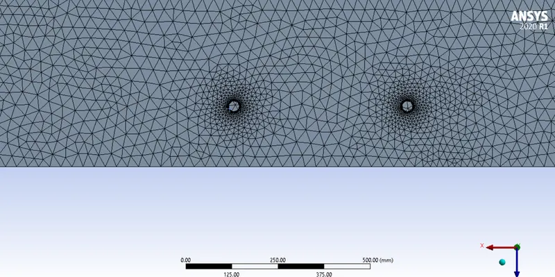
Case 4- (Mesh size of Outer enclosure = 70mm and inner enclosure = 20 mm)
- Meshing is done on the first enclosure(wind tunnel) with multizone (hexahedral) mesh with a size of 90 mm and the 2nd enclosure mesh size is set to 40mm
- All the other settings is set to same as the first case
Setup
- Steady state pressure based calculation is selected
- K-epsilon model is selected as this simulation involves capturing turbulence
- Material is se to air by default properties
- The inlet velocity is set to 25m/s
- The area of the surface facing the stream = (0.288*0.389)/2 + (0.03*0.05*2) = 0.59016
- and length of boundary in reference value is set to 0.6 and 1.044 metres respectively
- The method selected is SIMPLE method
- A plane is created to visualize the vectors in XY plane normal to z-axis with 0 distance from z origin so that it is at point where the geometry is symmetric
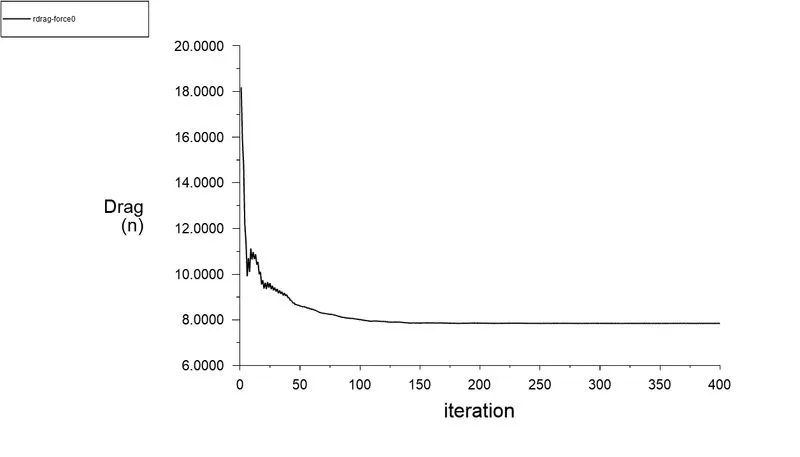
- Plot definitions is given for Coefficient of drag , Coeffecient of lift , lift force and drag force
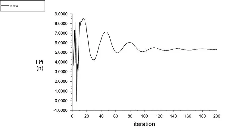
- the calculation is done for 200 iterations
- for the first case the desired y+ is set to 50 and hence the first layer thickness is taken as 0.7102 mm
Outputs
Case 1- (Mesh size of Outer enclosure = 100mm and inner enclosure = 50 mm)
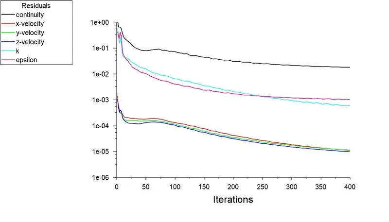
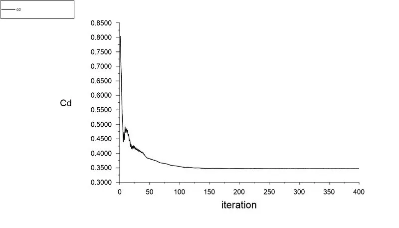
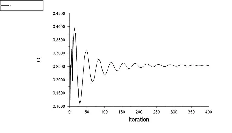
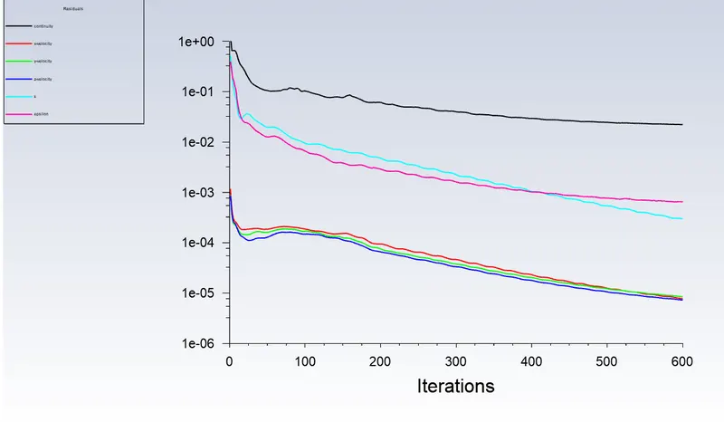
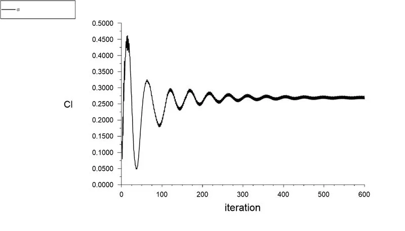
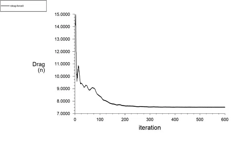
Plots obtained
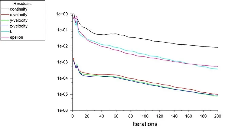
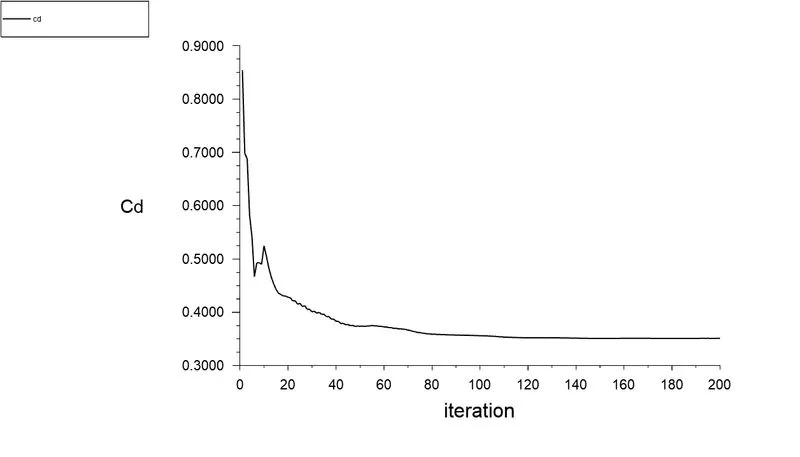
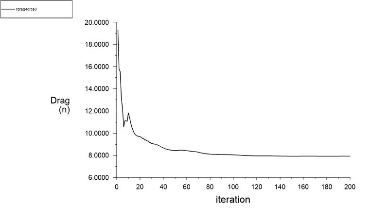
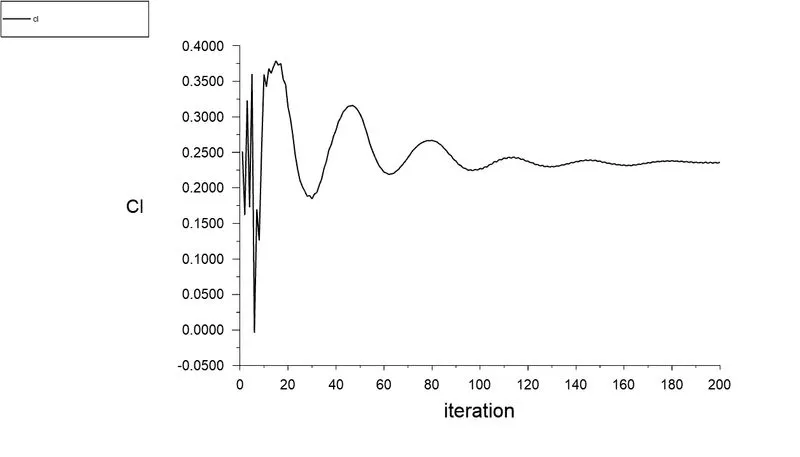
Values obtained
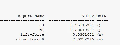
- The value for Coefficient of drag is obtained as 0.35 which is closer to the required value 0.33
Pressure contour
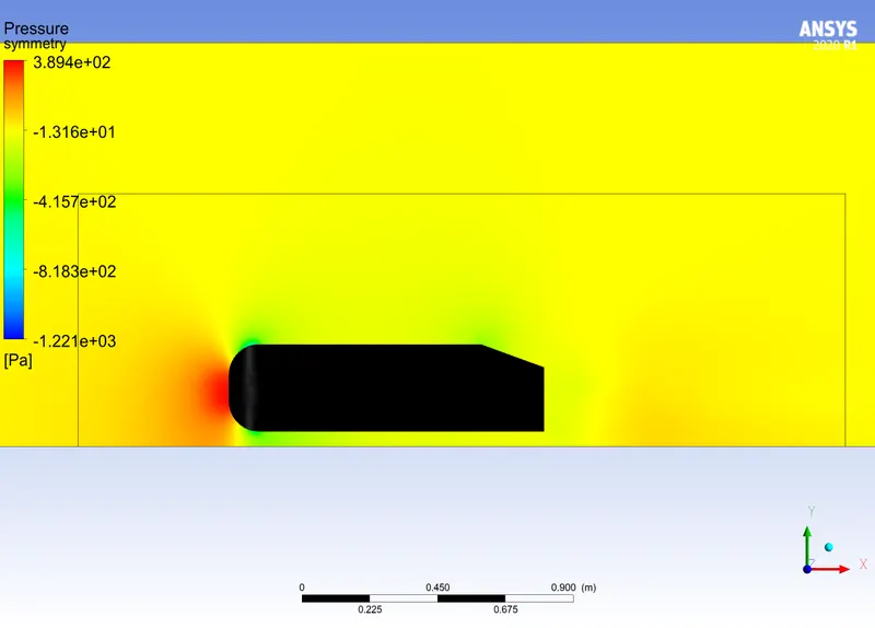
- The pressure is higher at front and lower at rear side of the ahmed body
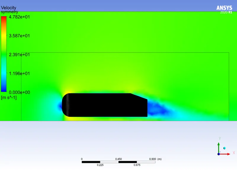
Velocity contour
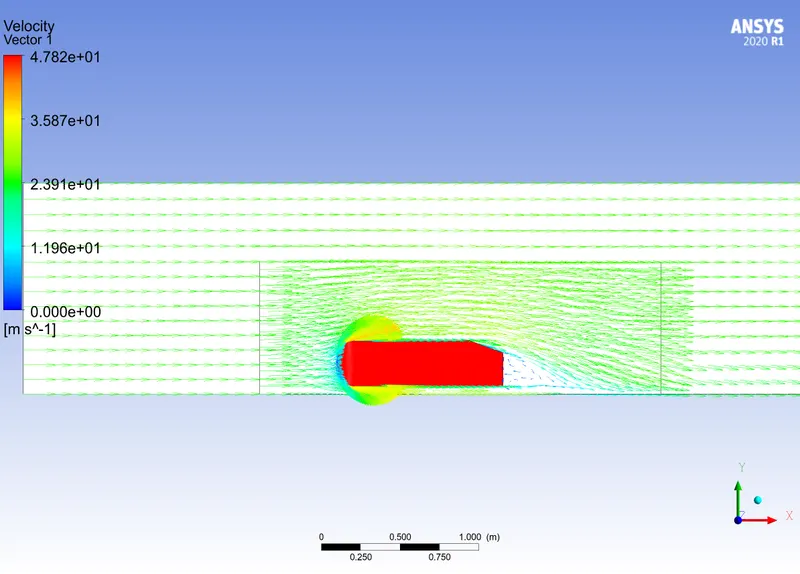
Velocity vector
Velocity stream line
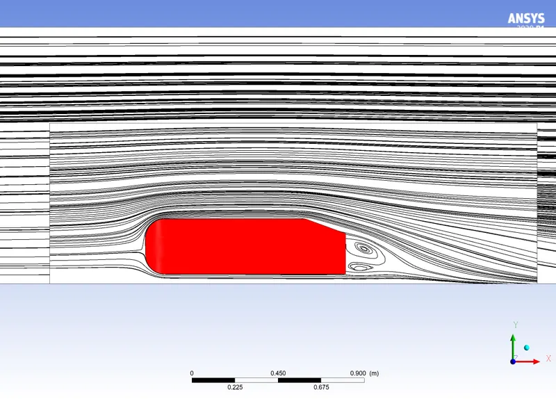
- A wake region is created at rear end of the ahmed body due to flow seperation and circular motion (vortex) is formed as a result of the movement of fluid from the higher pressure region through top and bottom of the ahmed body to lower pressure region (wake area).As discussed earlier the negetive pressure in the wake area is simply due to the flow seperation
- Also the velocity vectors has also been added in the above contour to visualize how th fluid particles behaves at the boundaries and it was spotted that the vortex is formed at rear side of the body validating the previous point
Velocity and pressure profiles at the point of seperation and wake region
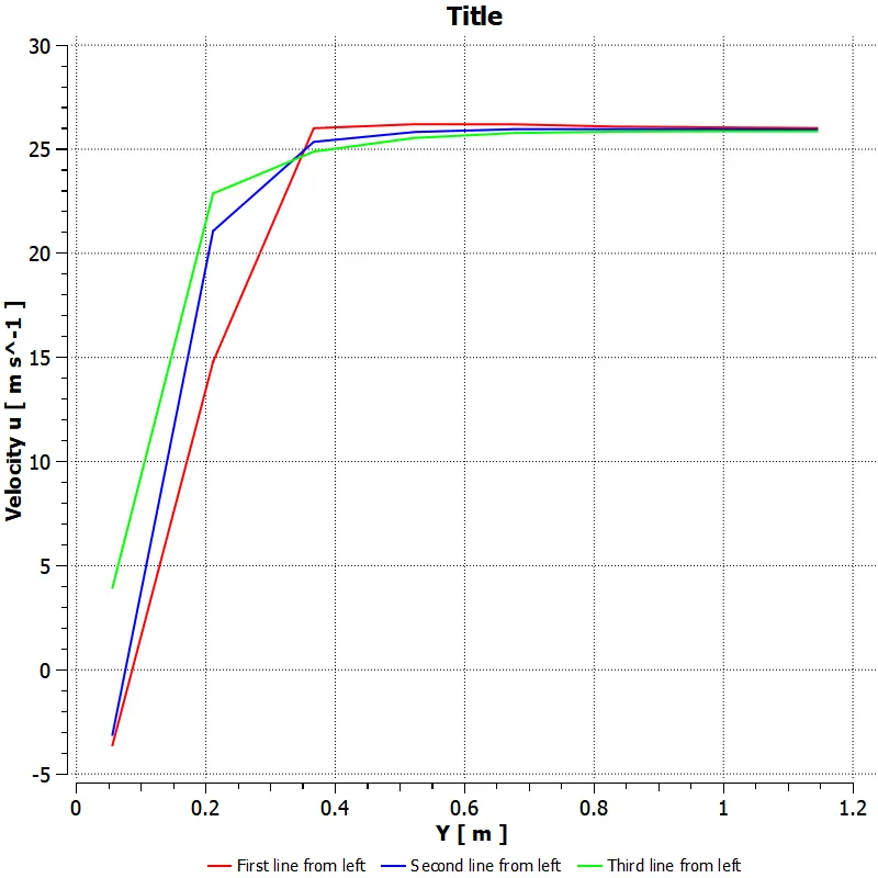
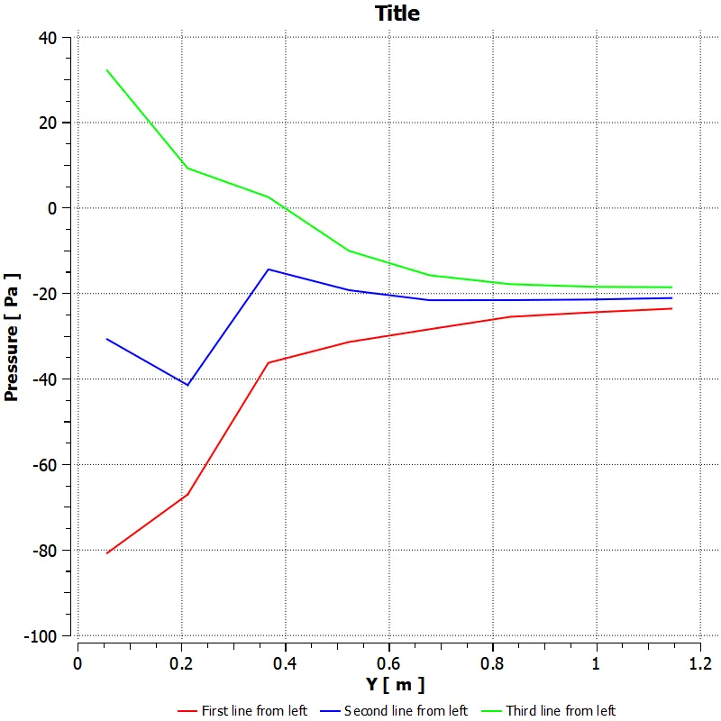
- For obtaining the profiles at wake region three lines were created along y-axis and the co-ordinates are
-
Line 1 = 1.1,-0.1,0 to 1.1,1.3,0
Line 2 = 1.2,-0.1,0 to 1.2,1.3,0
Line 3 = 1.3,-0.1,0 to 1.3,1.3,0
Velocity profile
Pressure profile
- The velocity variation in the three lines is different from each other, The first line is more involved in the wake region and the velocity is low at these areas which can be observed in the plots, the slope of the graph get reduced for the next lines as the wake region diminishes at some ditance from the back side of the ahmed body
- More negetive pressure is involved in the first line than the next line, and the third line is encounters high pressure which is created from the high velocity region
Mesh dependency test
- For this test I have considered all four cases for comparison of obtained solution
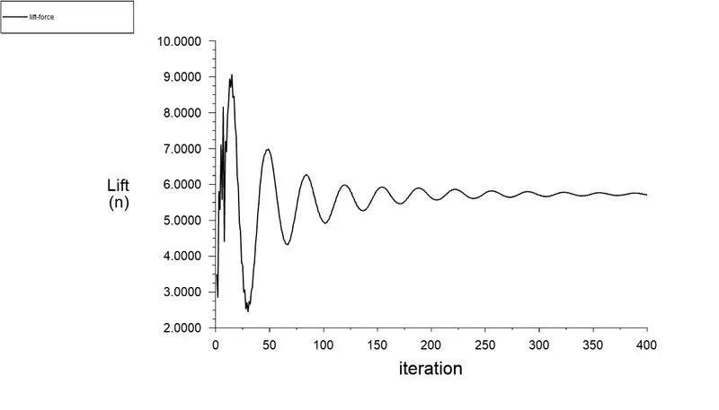
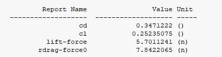
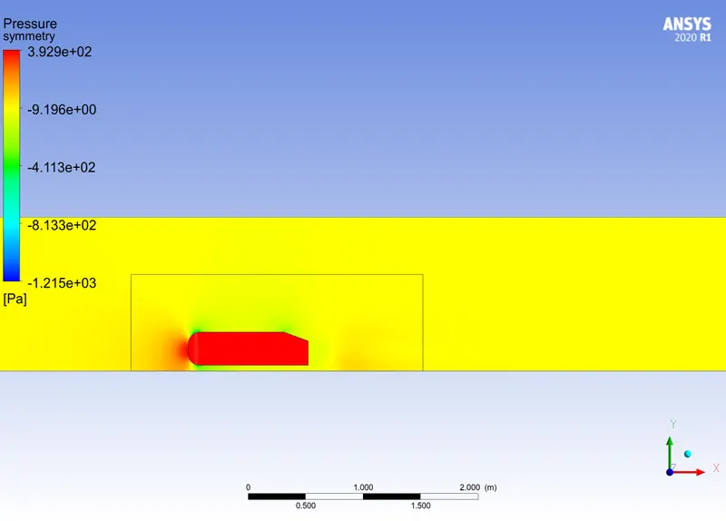
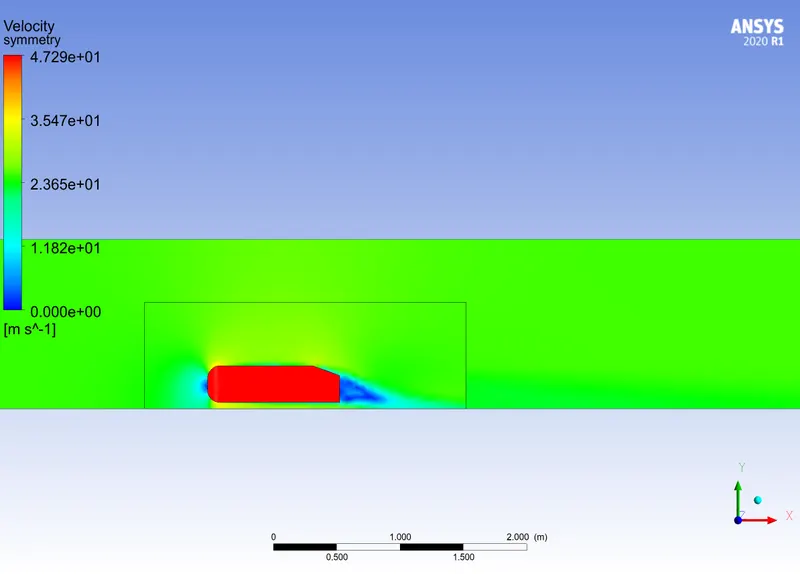
Case 2 -( Mesh size of outer enclosure = 90 and inner enclosure = 40 mm)
Plots obtained
Pressure contour
Velocity contour
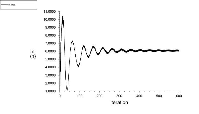
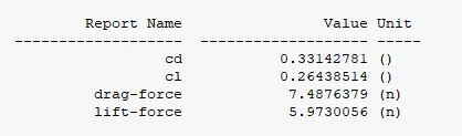
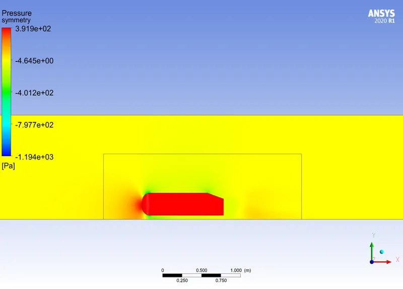
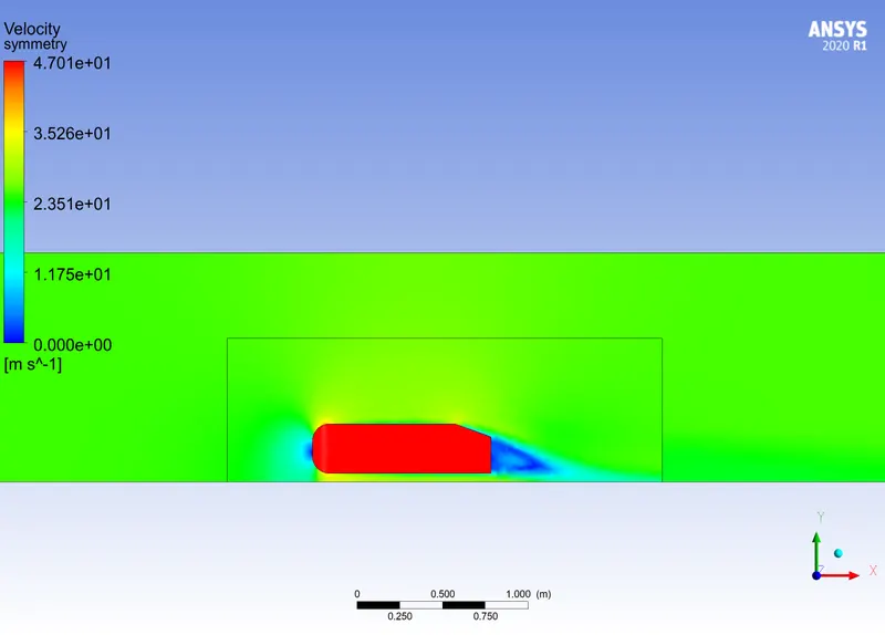
Case 3 -( Mesh size of outer enclosure = 80 and inner enclosure = 30 mm)
Plots obtained
Pressure Contour
Velocity Contour
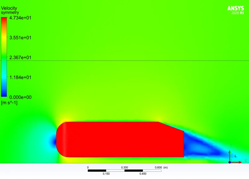
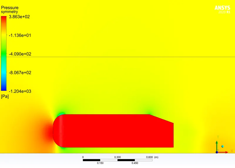
Case 4 -( Mesh size of outer enclosure = 70 and inner enclosure = 20 mm)
Plots obtained

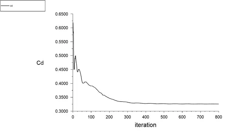
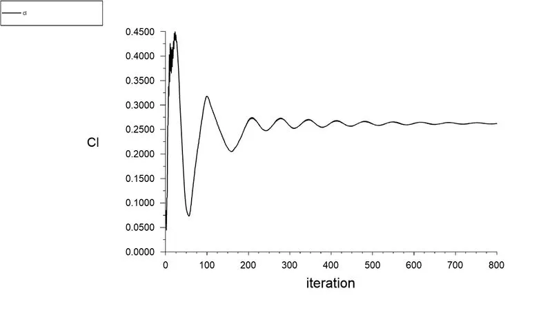
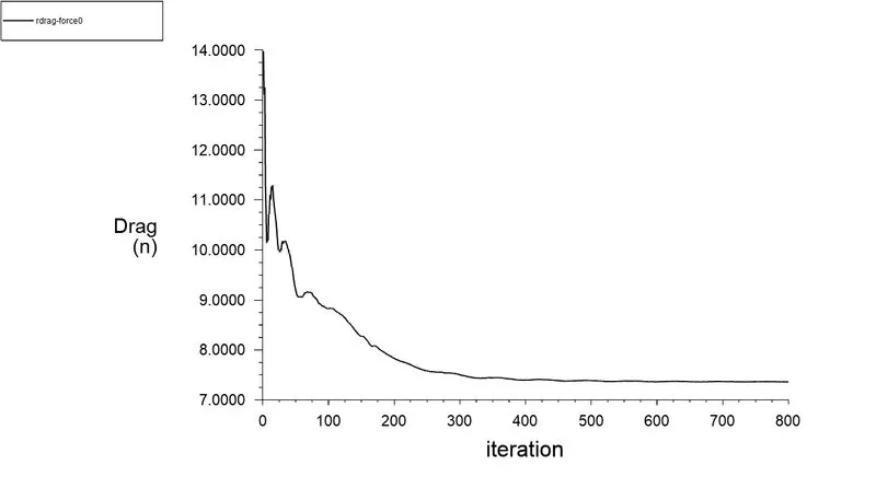
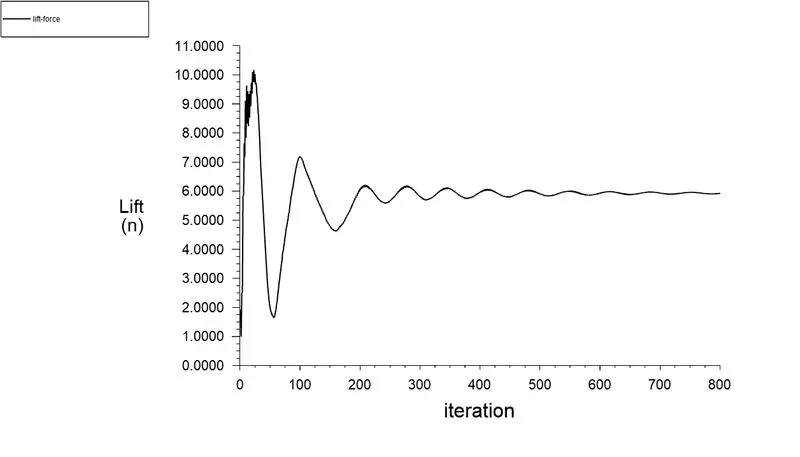
Velocity contour
Pressure contour
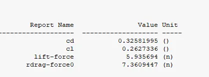
- Cd and Cl values are taken for comparison of all above cases
| Case | Number of elements | Cd | Cl |
| 1 | 150942 | 0.35115304 | 0.23619637 |
| 2 | 210395 | 0.347122 | 25235075 |
| 3 | 376932 | 0.33142781 | 0.26438514 |
| 4 | 1068559 | 0.32581995 |
0.2627336 |
Observations
- Out of all cases, they all show similiar plots and values with less variation in values
- As the mesh size is decresased the value seems to approach an accurate value
- When more number of elements are involved more iterations needed to get a converged solution
- It is always desirable to use small element size wherever we need accurate solution
Conclusion
- Ahmed body and its importance were discussed
- Reason for negetive pressure in the wake area was discussed
- Flow seperation and its significance were discussed
- Importance of using Y+ values were discussed
- Flow over an ahmed body was simulated and the datas were extracted and the value for drag was closer to the required value 0.33
- Mesh dependency test were done by refining the mesh in each cases