Week 3 - External flow simulation over an Ahmed body.
AIM
External flow simulation over an Ahmed body
OBJECTIVE
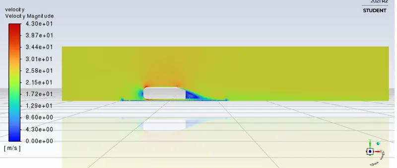
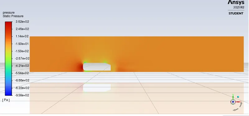
- To generate velocity and pressure contours.
- The drag coefficient plot for a refined case. ( For velocity of 25m/sec, the drag coefficient should be around 0.33).
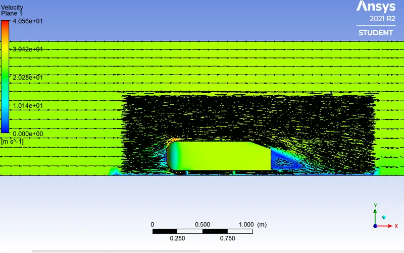
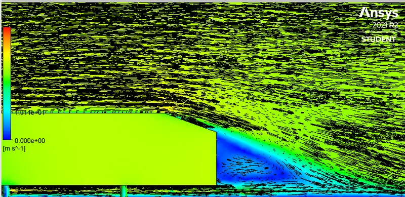
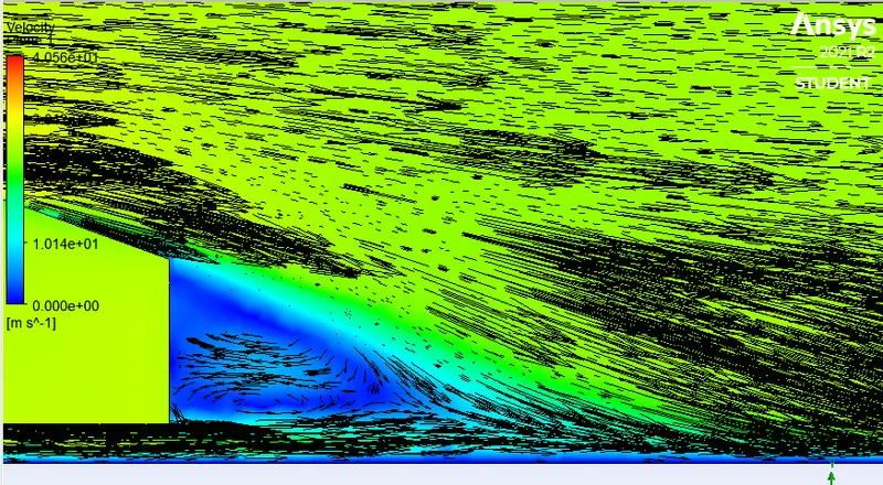
- The vector plot clearly showing the wake region.
- Perform the grid independency test and provide the values of drag and lift with each case.
THEORY
Ahmed body and it's importance
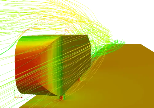
The Ahmed body is a generic car body (a simplified vehicle model). The airflow around the Ahmed body captures the essential flow features around an automobile. The Ahmed Body was first created by S.R. Ahmed in his research “Some Salient Features of the Time-Averaged Ground Vehicle Wake” in 1984. Since then, it has become a benchmark for aerodynamic simulation tools. The simple geometrical shape has a length of 1.044 meters, height of 0.288 meters, and a width of 0.389 meters. It also has 0.5-meter cylindrical legs attached to the bottom of the body and the rear surface has a slant that falls off at 40 degrees. Although it has a very simple shape, Ahmed body allows us to capture characteristic features that are relevant to bodies in the automobile industry.
This model is also used to describe the turbulent flow field around a car-like geometry. Once the numerical model in validated, it is used to design new models of the car.
Simulation Procedure
External flow simulation over an Ahmed body
Ahmed body, dimensions in mm
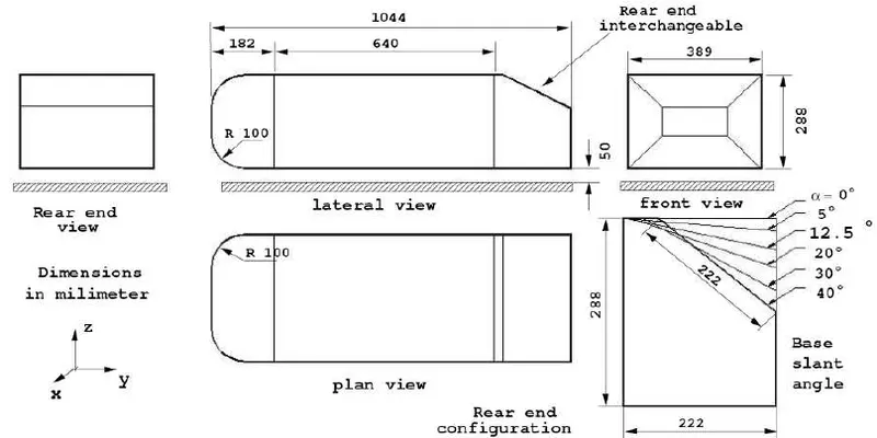
Open Ansys Workbench, select fluid flow(fluent) and create geometry in spaceclaim.

Create an enclosure on the Ahmed body (uncheck symmetric dimensions)
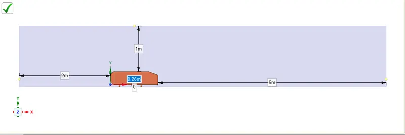
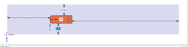
Create another enclosure to add a region of refinement infront of the Ahmed body and also on the wake region. This is called as local refinement. The mesh will be more finer inside this box.
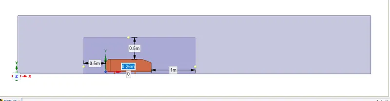
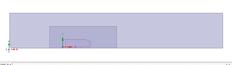
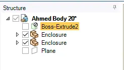
Since two enclosure is added, there will overlapping of the meshes of two boxes while meshing. To avoid this problem use the interference option. Set the share topology option to share for both the enclosures.
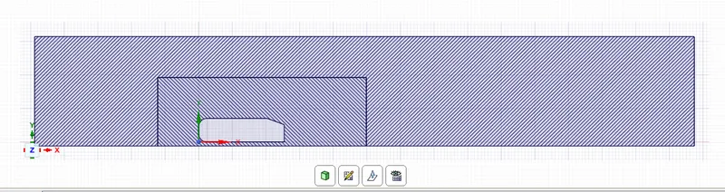
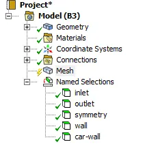
After creating geometry, close spacelaim then the next step is to create the mesh. Before meshing name the boundaries.
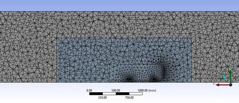
Create hexahedral mesh by using multizone method
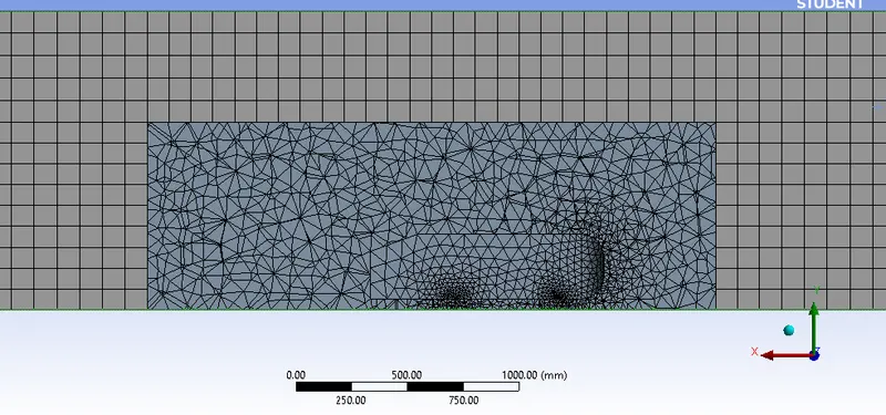
Use the sizing option to make the mesh inside more refined
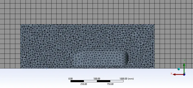
Add inflation layers to the boundary wall of the Ahmed body
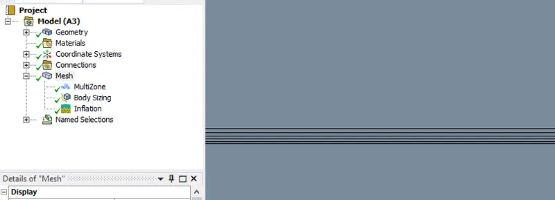
Meshing is complete. Double click on setup to open CFD solver.
Check the mesh quality.
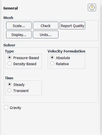
Choose pressure based solver and the simulation is done as steady state simulation.
Set the viscous model to K-epsilon (standard).
Set the boundary conditions (inlet velocity = 25m/s).
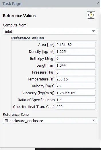
The reference values are computed from inlet.
Initialize the solution
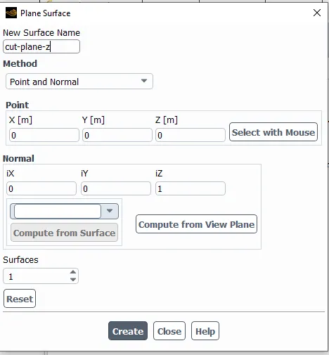
Create a cut pane along the Z axis to get the velocity and pressure contour plots.
Results
Outer enclosure = 95mm
Inner enclosure = 30mm
Face sizing for Ahmed body = 10mm
Inflation for Ahmed body = 5 layer with first layer thickness
Residual plot
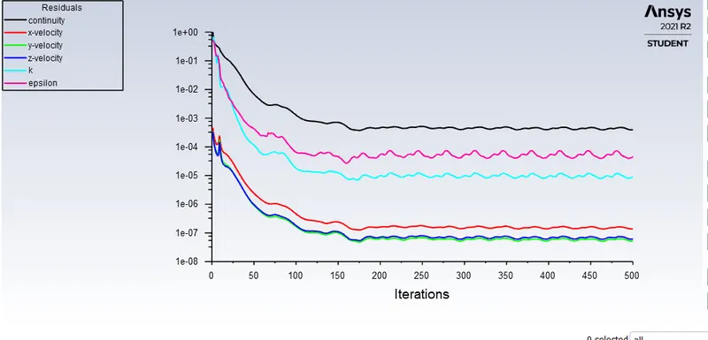
The solution has converged after 250 iterations.
Coeffecient of drag
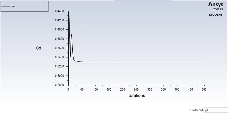
`C_D` = 0.329
Coeffecient of lift
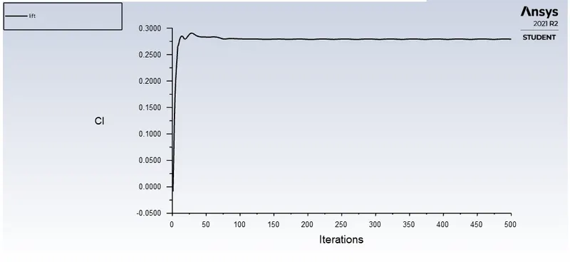
`C_L`= 0.279
Velocity contour plot
Pressure contour plot
Vector plot
Significance of the point of separation
Flow separation or boundary layer separation is the detachment of a boundary layer from a surface into a wake. Separation occurs in flow that is slowing down, with pressure increasing, after passing the thickest part of a streamline body or passing through a widening passage. The presence of the fluid viscosity slows down the fluid particles very close to the solid surface and forms a thin slow-moving fluid layer called a boundary layer. The flow velocity is zero at the surface to satisfy the no-slip boundary condition. Inside the boundary layer, flow momentum is quite low since it experiences a strong viscous flow resistance. Therefore, the boundary layer flow is sensitive to the external pressure gradient (as the form of a pressure force acting upon fluid particles). If the pressure decreses in the direction of the flow, the pressure gradient is said to be favorable. In this case, the pressure force can assist the fluid movement and there is no flow retardation. However, if the pressure is increasing in the direction of the flow, an adverse pressure gradient condition exists. In addition to the presence of a strong viscous force, the fluid particles now have to move against the increasing pressure force. Therefore, the fluid particles could be stopped or reversed, causing the neighboring particles to move away from the surface. This phenomenon is called the boundary layer separation.
When the boundary layer separates, it's remnants form a shear layer and the presence of a separated flow region between the shear layer and surface modifies the outside potential flow and pressure field. In the case of airfoils, the pressure field modification results in an increase in pressure drag, and if severe enough will also result in stall and loss of lift, all of which are undesirable.
Another effect of boundary layer separation is regular shedding vortices, known as a Kármán vortex street. Vortices shed from the bluff downstream surface of a structure at a frequency depending on the speed of the flow. Vortex shedding produces an alternating force which can lead to vibrations in the structure. If the shedding frequency coincides with a resonance frequency of the structure, it can cause structural failure. These vibrations could be established and reflected at different frequencies based on their origin in adjacent solid or fluid bodies and could either damp or amplify the resonance.
Reason for the negative pressure in the wake region
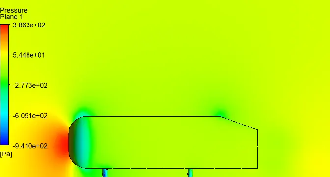
When the air moving over the vehicle is separated at the rear end, it leaves a large low pressure turbulent region behind the vehicle known as the wake. Wake is the region of recirculating flow immediately behind a moving or stationary blunt body, caused by viscosity, which may be accompanied by flow separation and turbulence. The flow separates from the surface and creating a highly turbulent region behind the body. The pressure inside the wake region remains low as the flow separates and a net pressure force (pressure drag) is produced. This wake contributes to the formation of pressure drag, which eventually reduces the vehicle performance. Due to the boundary layer separation vacuum region is created.
Grid independency test
| No. of cells | `C_D` | `C_L` |
| 144874 | 0.390 | 0.256 |
| 485239 | 0.361 | 0.306 |
| 497385 | 0.328 | 0.285 |
| 500915 | 0.329 | 0.279 |
CONCLUSION
- The simulation of flow over an Ahmed body was conducted. The simulation was ran for velocity of 25 m/sec with the default air properties in fluent. By refining the mesh, drag coeffecient close to the analytical result was reached.
- When the flow moves past the Ahmed body, low pressure region was created rear end of the body called as wake. It is due to the boundary layer separation. The point of separation has a significance, as the point of separation changes the coeffecient of drag changes.
- The Y plus function is important in getting accurate results. It is important in turbulence modeling to determine the proper size of the cells near domain walls.
- Mesh independency test was conducted and the independency was proved. By running the simulation for various element sizes convergence was reached. Additional mesh refinement didn't affect the results.