Week - 3 Drop test Challenge
Aim:- Drop test for mobile phone model using Ls-dyna and setup the file.
Object:-
- To material creation as per requirement for the different part.
- To section creation for solid and shell.
- To define for part such as material and section ID.
- To create Boundary or set segment and node set conditions such as construction.
- To define contact definition for phone and plate.
- To create veloctiy which will assign to the phone.
- To define the control keyword so that we will control simulation llike time of simulation printing results every defined time.
Procdure:-
1.Import file (file>open>Ls-dyna keyword file).
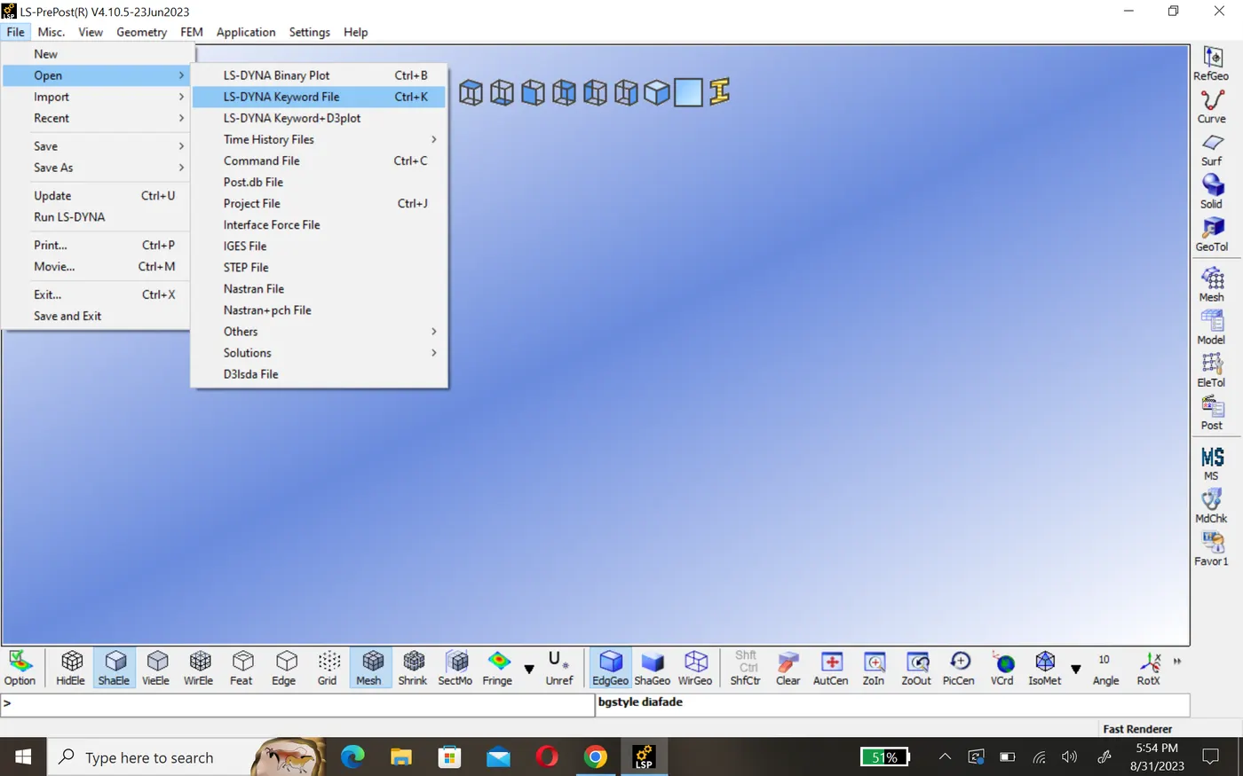
2.Creating section:-
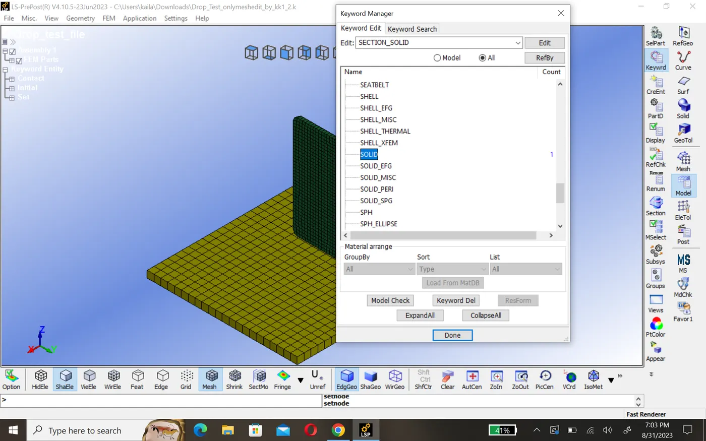
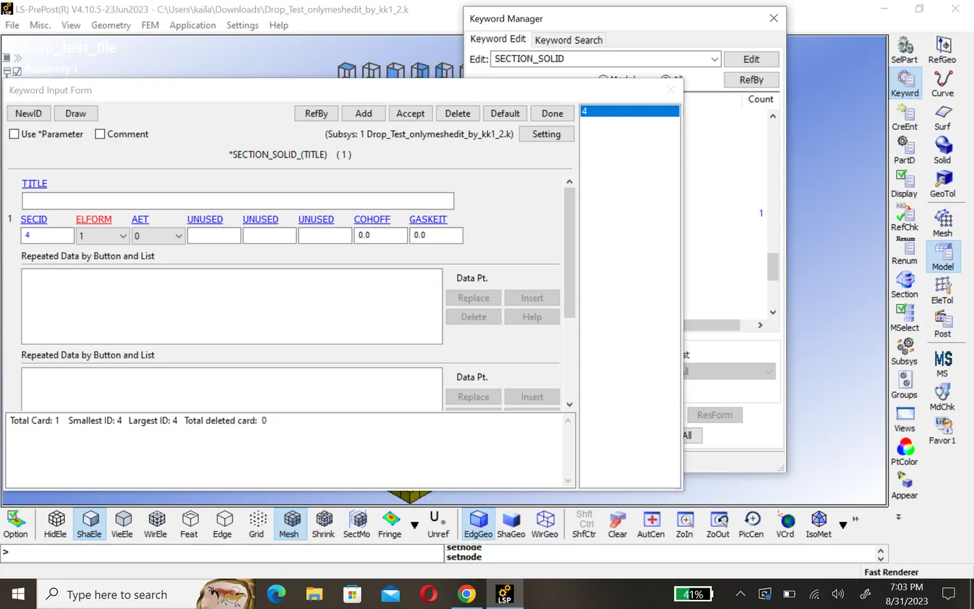
In order to distinguish between the type of element we have to define the section keyword for shall and solid . to creating section(model>keyword>all>section>shall/solid). Here we have to define thickness and type of element formulation here all element constrained in all direction.
3.Material creation:-
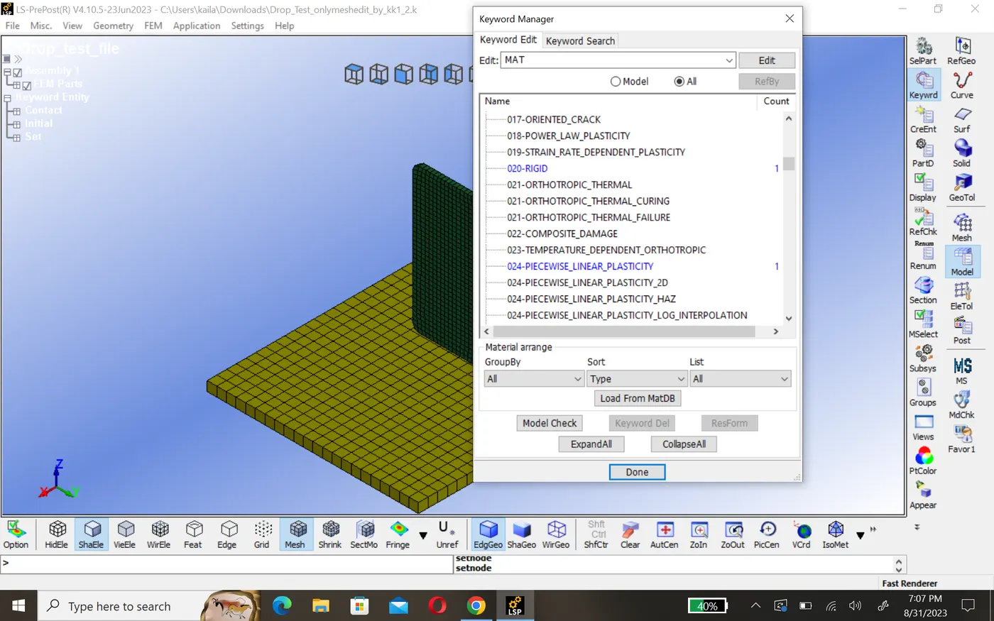
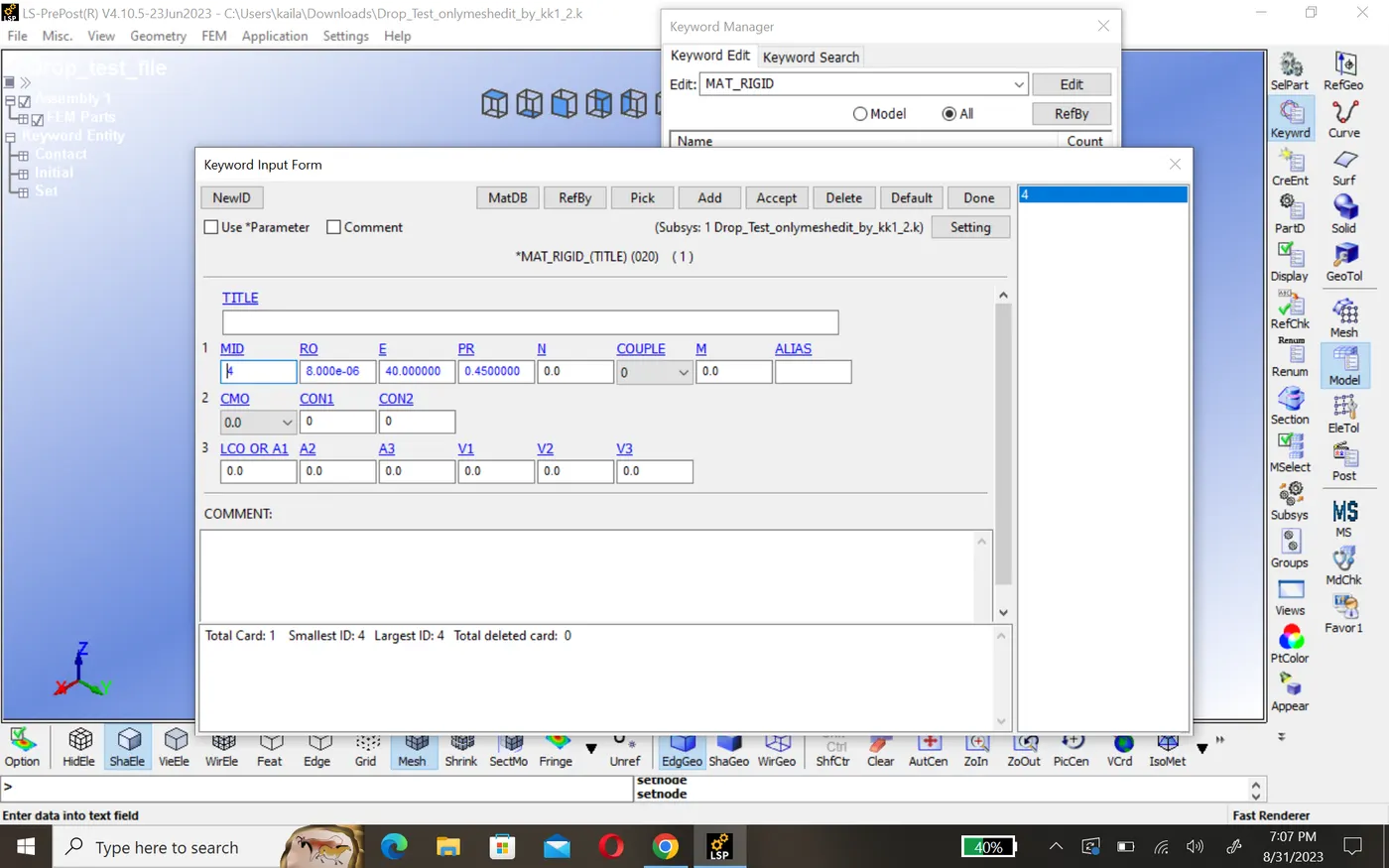
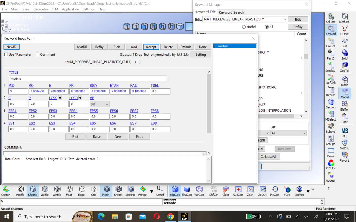
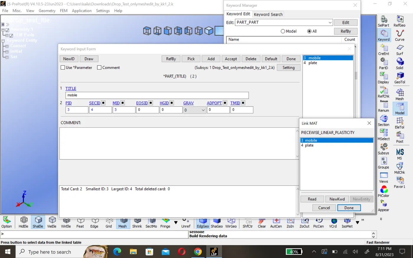
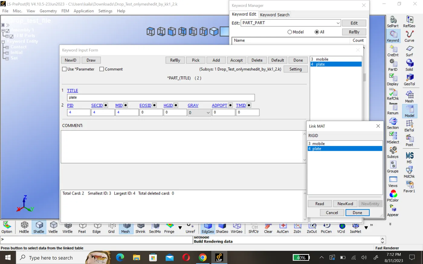
In order to run simulation material of every part is necessary. create material for a plate which is rigid and for phone here considered as aluminium. model>keyword>mat>020_rigid(plate) and 024_picewise_linear_plasticity).
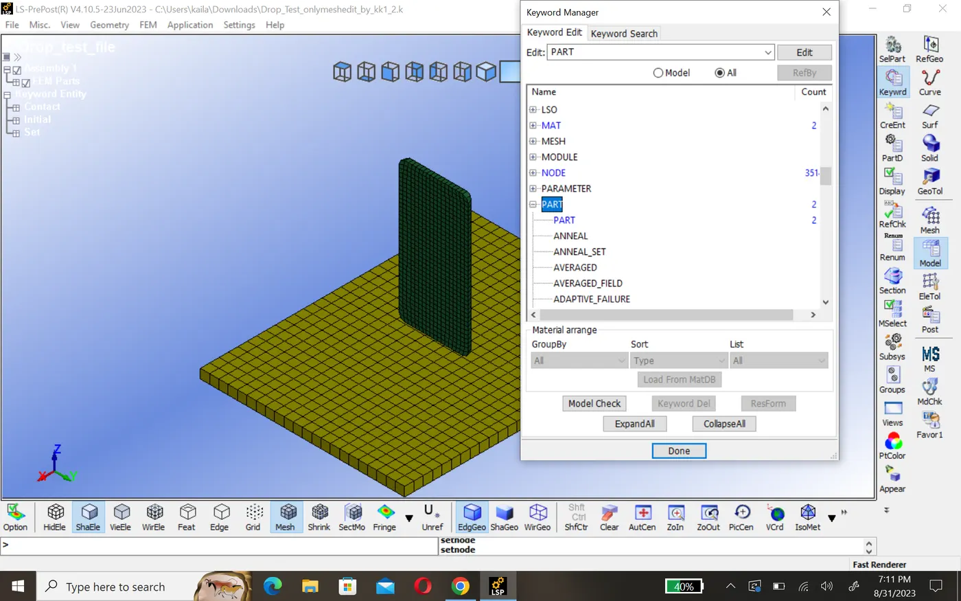
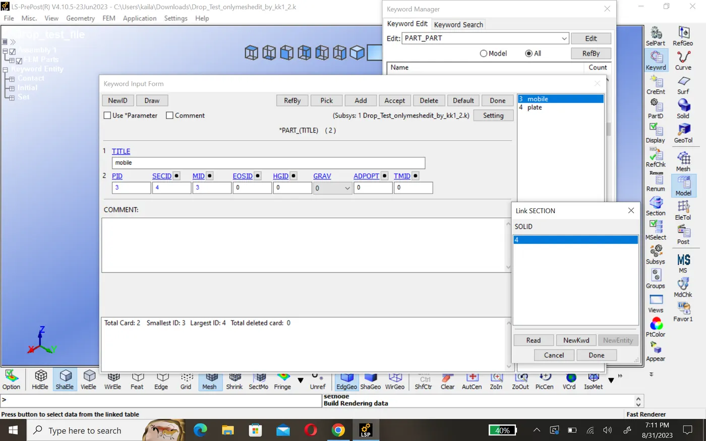
4. Part creation:-In this step we assign section and mat id in part for different part's and create part id. or give titel.model>keyword>part
5.Creation of set segment:-
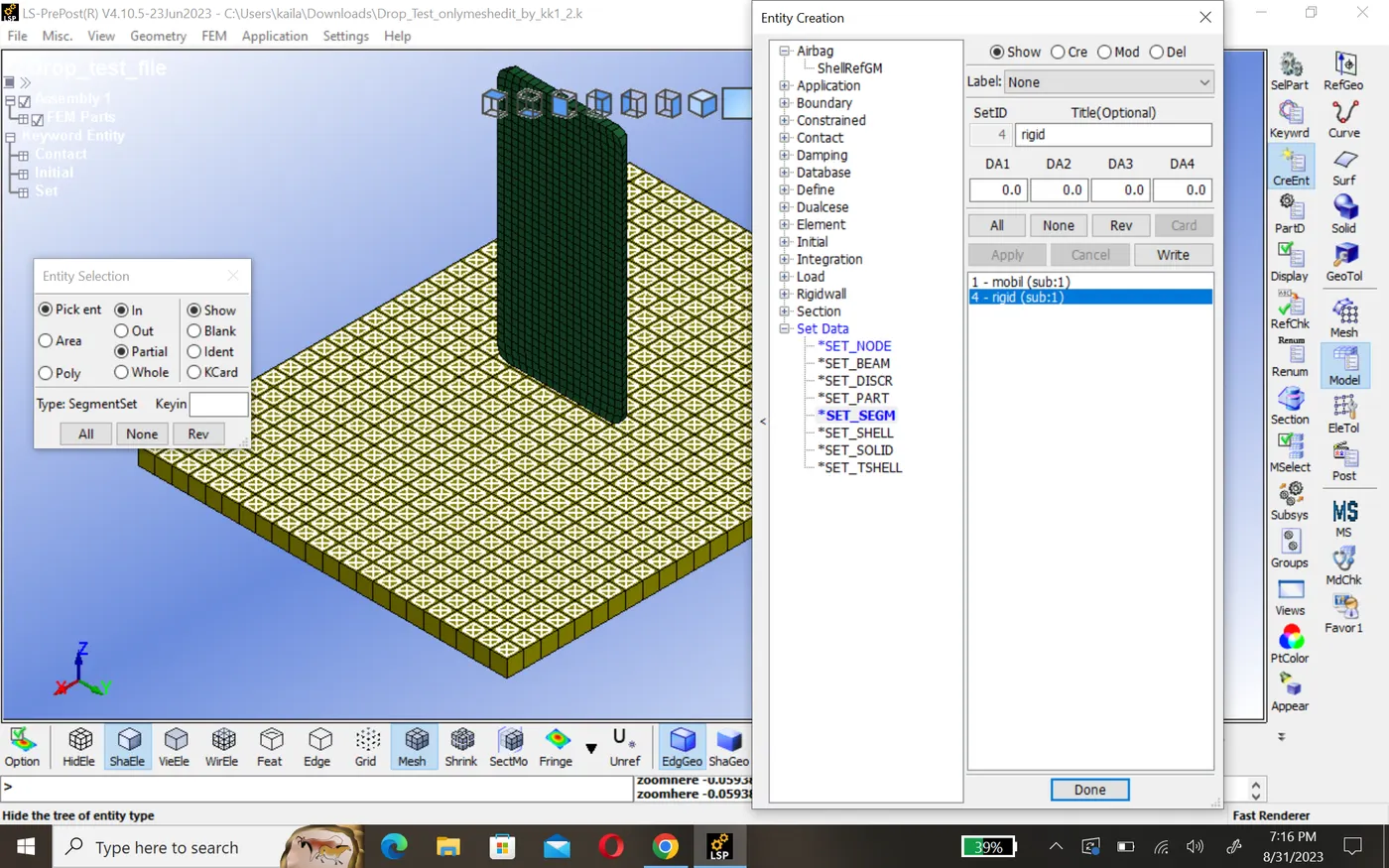
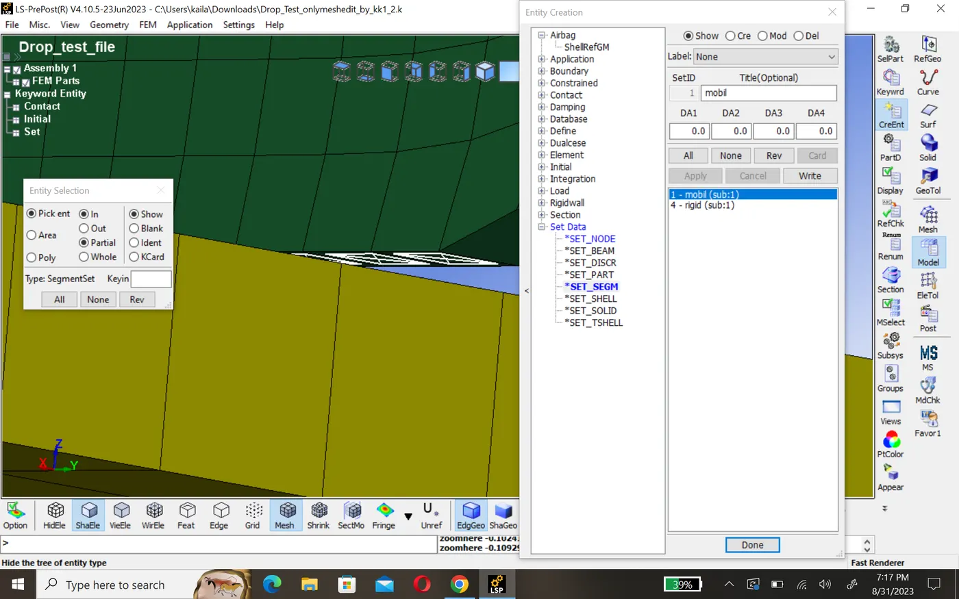
Here we create set segment for both part we select that element of part's which will be in contact during simulation time.model>creating element>set data>set segm
6.Define contact:-
In order to impact take place between phone and plate there should be contact definition or phone will pass through plate. here phone are slave and plate are master nodes. model>keyword>all>contact>automatic_surface_to_surface_contact
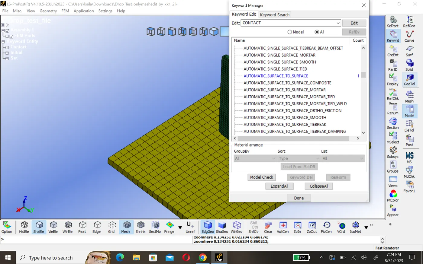
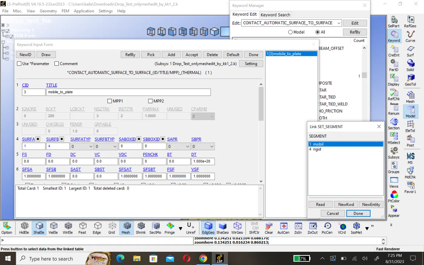
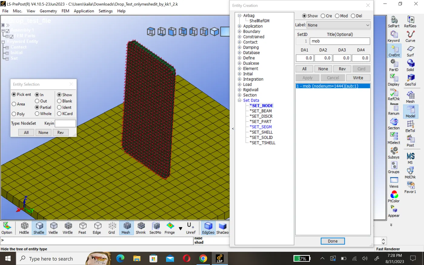
7. create node set:-
In order to simulation we create node set id for that part(phone) which move during the simulation. we do it before creating inital velocity card.
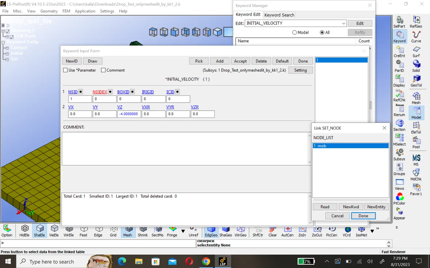
8.Inital velocity:-
In order to move phone twords plate we are assuming the veloctiy 4mm/ms in negative direction. here select the node set and input velocity in which direction it should move.
9.Control keyword:-
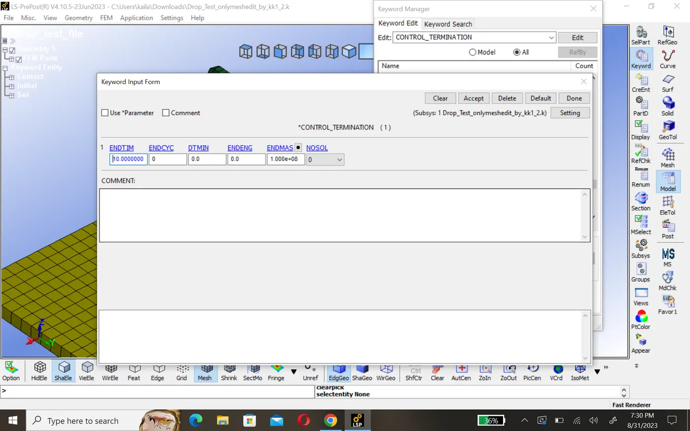
to control the simulation time we use control termination card. this key word is used to control simulation by time, 5ms
10.Output request:-
using data base pannel we can request such as animation file energy data, contact forces etc,
Binary3dplot:- the complete state dump interval as given in *DATABASE_BINARY_D3PLOT serves as the time step to be used in the material model driver run. plotting information is saved in core for the interactive plotting phase.
ASCII_option this option is used to reade the data of following
GLSTAT- This keyword reade the energy like KE, PE,IE
MATSUM-Every material part energy due to deformation
RCFORCE- contact force between them
SLEOUT- sliding force due to contact
SPCFORCE- single point contact force
Result:-
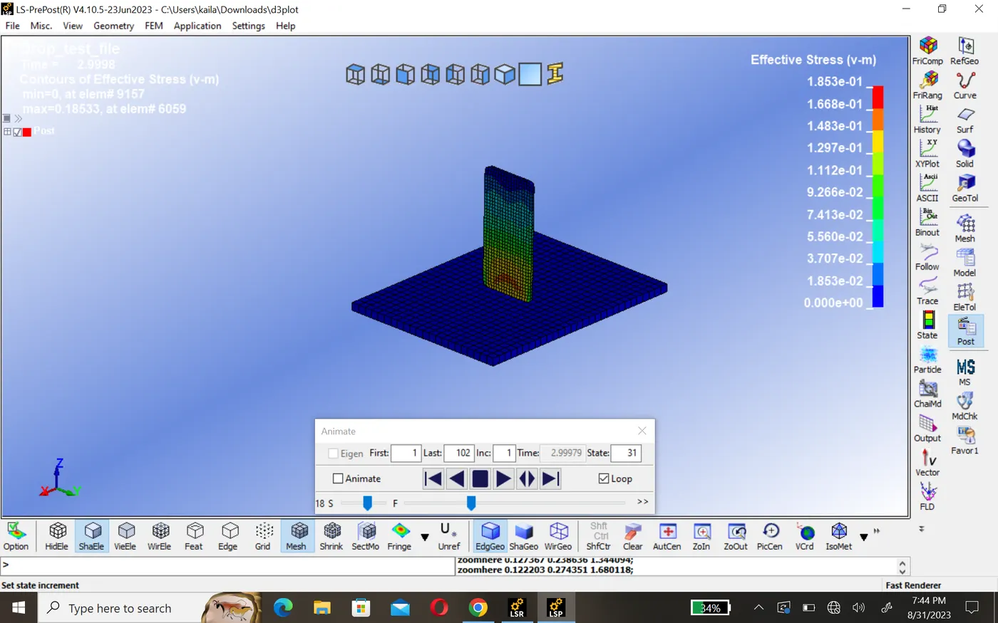
At initally before hitting plate there zero contact force, once phone hit the plate the contact forces starts building and reaches maximum contact force. After that rigid wall forces are droping down beacuse velocity droping, this is due to rigid wall at time
Conclusion:- I'm try to include more detail in my report so that everyone understand isaliye.