Week - 3 Drop test Challenge
Introduction
“Drop test” is free fall of component. It is generally performed to check the ability of product to withstand suddenly applied loads. Drop test is one of the functional test requirements of crash frame for certification, hence crash frame has to qualify through the drop testing as per guide lines before it goes to market for actual use.
The “Drop Test” also called as “Shock Test”, which is designed to measure the durability of equipment during loading/unloading and transportation.
_____________________________________________________________________________________________________________________________________
Analysis
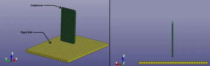
- Here we will see the Drop Test of simplified model of Cellphone on the concrete ground.
- There will be free fall of a Cellphone on the ground, which generally made of concrete.
- So we will take the material for Cellphone as Steel and for Rigid body will be concrete.
- Here the reason for taking the concrete as a rigid body is to see the effects like phone drops on the floor at home.
_____________________________________________________________________________________________________________________________________
Geometry
_______________________________________________________________________________________________________________________
Material Specifications:
Cellphone:
Material Model: PIECEWISE_LINEAR_PLASTICITY (024)
Density: 0.0078500 gm / mm3
Elastic Modulus: 200000 Mpa
Poisson’s Ratio: 0.25
Tensile Yield Strength: 350 Mpa
Rigid Wall:
Material Model: RIGID (020)
Density: 0.0024000gm / mm3
Elastic Modulus: 41000 Mpa
Poisson’s Ratio: 0.21
_____________________________________________________________________________________________________________________________________
Procedure:
- First of all open the L S DYNA Keyword file named as “Drop_Test_onlymesh.k” in LS-PrePost.
- This file contains, Shell as well Solid bodies as shown in below image:
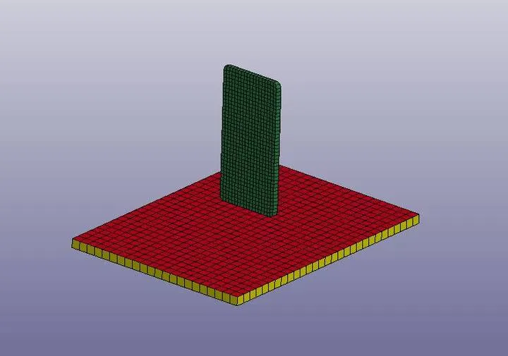
- As per above image, we have sheet made of shell elements in red color.
- We can do analysis with considering sheet as a Rigid Wall of below solid plate as a rigid wall.
- For easy way to handle the Phone as well as Rigid wall, we can use solid rigid wall.
- So we can delete red color sheet part.
- Now create different cards necessary for the simulation.
Part:
- Now we have only two parts as shown in below image.
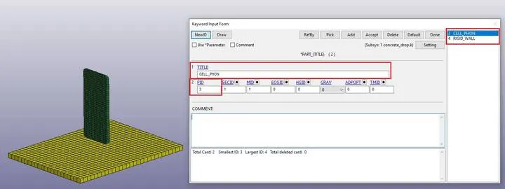
- As shown in above image, first of all give ID (which has been given already) and Title according to part.
Boundary:
- After creating parts, create boundary condition for rigid wall.
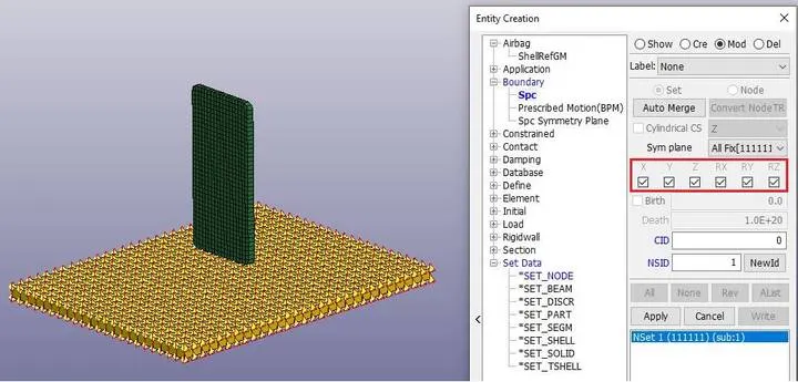
- As shown in above image, we can see that “SPC” single point constraint is created for Rigid Body by selection as a part in “Entity Creation” menu.
- Here all the Degrees Of Freedom have been locked for Rigid Body.
Initial Velocity:
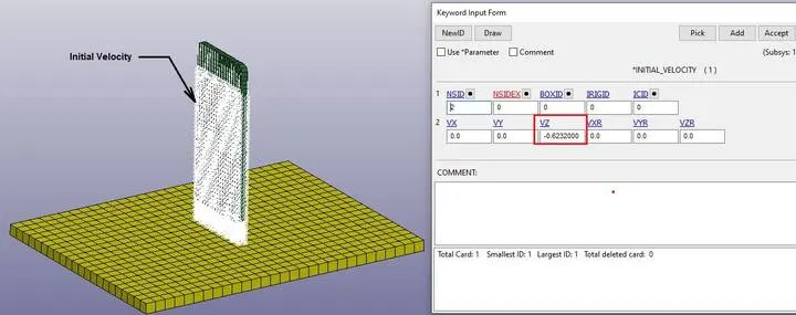
- Here the drop of the Phone will be free fall.
- So free fall of Phone from 19.8 mm distance in z-direction, will be 0.6232 mm/ms.
- So create Initial velocity from Keyword Manager and give the velocity as -0.6232 mm/ms in negative z-direction. As shown in below image.
Section:
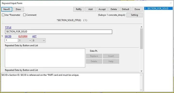
- Here we are working on only solid elements, so create section for solid elements.
- Give title and ID as per convenience.
- Here Element Formulation is set to 1. Which is default and it describes the elements with “one point reduced integration”.
Material:
- Create material cards for Phone as well as Rigid body as given below.
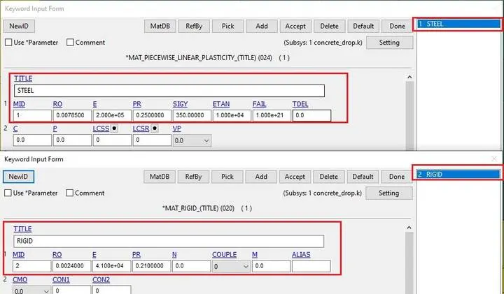
- Assign all details related to material specification as described above.
- After creation of section and material cards, we have to apply it to the part.
- So in Part, assign MID and SECID according to ID’s of Phone and Rigid Wall.
Contact:
- Now for the reaction behavior of the interface, we have to create Contact Interface between Phone and Rigid Wall as given bellow.
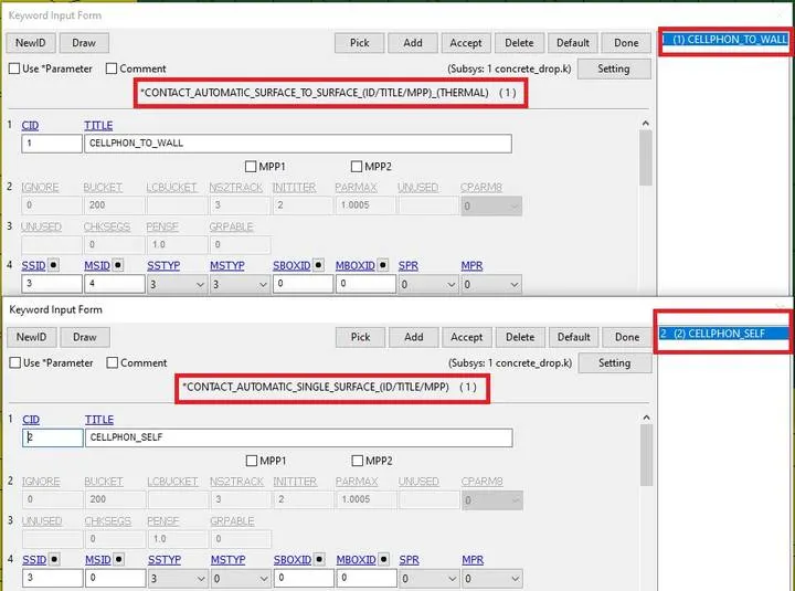
- Create “AUTOMATIC_SURFACE_TO_SURFACE” for contact between Phone and Rigid Wall.
- Create “AUTOMATIC_SINGLE_SURFACE” for self interaction between elements of Phone.
Control:
- After creating all boundary conditions and contacts, create a card for termination.
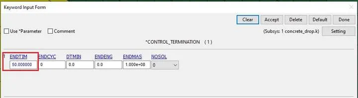
- “CONTROL_TERMINATION”, helps for termination the simulation period.
- By giving “ENDTIM”, up to that value we can run the simulation and then terminate it.
- Here, Termination time is given a 50 ms.
Database:
- Now after all conditions and termination details, we can generate output requests or results what we want from the analysis.
- For that, we have to create cards for output. For animation and other part related data, create “BINARY_D3PLOT”, from database and “GLSTAT”, “MATSUM”, from ASCII_option in database.
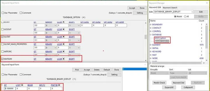
- Here we have given the time 0.1 ms for reporting all the data at each 0.1 ms from 0 to 50 ms for the accuracy.
- After creation of all necessary cards, save the Keyword file with “.K” extension.
_____________________________________________________________________________________________________________________________________
Calculation:
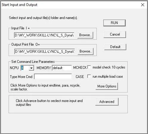
- Now for calculation of all analysis, run the simulation as per availability of the core of CPU bu giving the value in “NCPU”.
Timing Information:
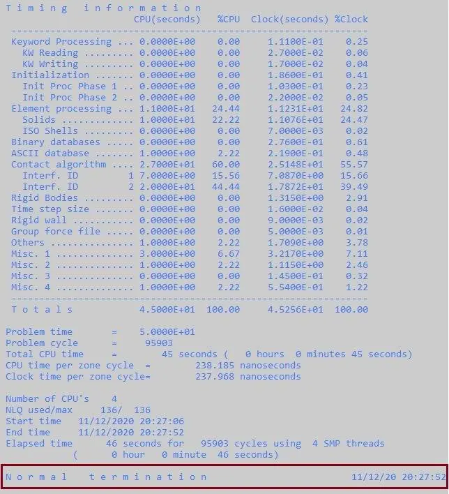
- Make sure that Termination is Normal as shown in above image.
_____________________________________________________________________________________________________________________________________
Results:
- Open the Binary “d3plot” file in LS-PrePost and check the results.
Effective Von-mises Stress:
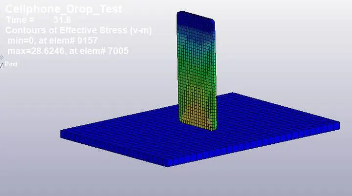
- Here we can see that maximum stress generating is 28.6246 Mpa at 31.8 ms.
Displacement:
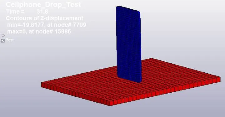
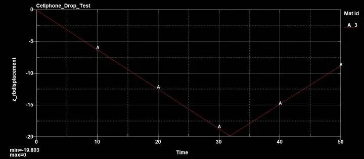
- From above result, we can ensure that Phone has traveled up to 19.8 mm distance which was kept at initial condition.
Global Energies:
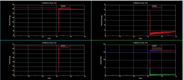
- From above image , we can say that, when Phone touches the Rigid Wall, Kinetic energy decreases and Internal Energy Increases at 31.8 ms.
- After retraction of Phone, again Kinetic energy increases and Internal Energy decreases and then both becomes constant.
- From above plot we can see the Energy conservation by observing Total Energy graph.
- Here we can also see some energy fluctuations due to vibration in Phone after impact.
Contact Energies:
Phone to Rigid wall Interface:
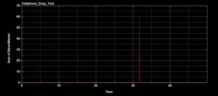
- This is the sum of Phone and Rigid Wall contact energy for Phone to Rigid Wall interface.
Phone interface:
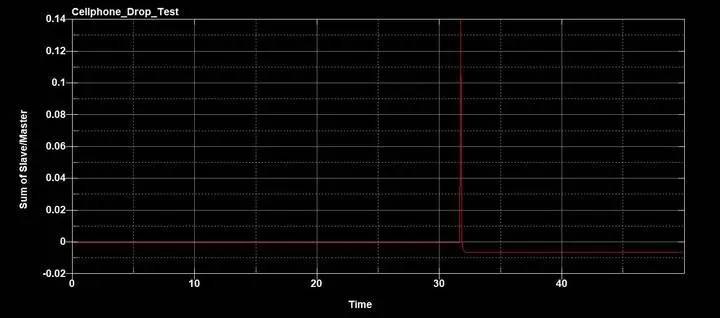
- This is the contact energy due to self interaction of Phone.
Contact Forces:
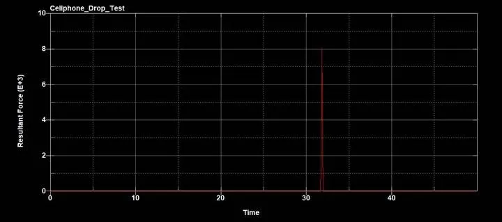
- Here we can see the resultant contact force acting on the Phone due to impact at 31.8 ms.
_____________________________________________________________________________________________________________________________________
Conclusion:
This concludes Material modeling strategy considerably acceptable for this case; however different Material model should be checked with different loading condition to arrive at correctness of modeling strategy of the simulation. The simulation results adds confidence to the Material modeling approach and endorses the mesh size, element selection and contact definitions specific for problem describe in this analysis. This drop test simulation helps to improve the design of Cellphone while it is in design life cycle. We can try different Material models and also check for the various output results for more accurate results.