Week - 3 Drop test Challenge
Aim: Learn to create an input deck from scratch and create a complete simulation file from this to perform a drop test.
Process:
- Import Drop_Test_onlymesh.k file to LS-PrePost and click on model and part command in the Right Toolbar
- Navigate to Keyword manager and find out which keywords need to be added for the simulation to run.
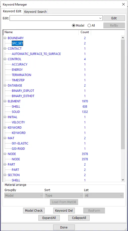
- Fig 1 shows which keywords exist already. We will take a look at which cards to add, why and how to add them. Its better to create all these cards using create entity option as we can specify the node sets/surface/ elements associated with it with ease.
- Boundary Conditions: Proceed to Create Entity Tab in right toolbar and under Boundary click on Single Point Constriants SPC, under spc navigate to Create tab. Click on the DOF you want to restrict and navigate to Sel. Nodes(0) tab. Here you can define the restriction by selecting Node set/ elements/ Parts ID/ Part Selection.
- Control: Notice that Keyword manager is sometimes more easier to create Keywords than Create entity option. To create Control Cards (Accuracy, Energy, Termination, Timestep) it is easy to use Keyword manager. Once you open the keyword you want to create it asks for inputs needed to create that keyword. This input may be output return file, simulation file, controls for time stepping and output measurement.
- Database: D3PLOT file provides the database for entire model. Usually output files with D3 are used to control, restart, display history/data about the whole simulation file. However you can request some specialized outputs according to needed data for analysis. Common important output files are : BINARY_D3PLOT, BINARY_D3THDT
- ASCII Output Files: GLSTAT, MATSUM, RCFORC, SLEOUT, SPCFORC
- Element: There is no need to add seperate node and element data while it is done automatically. But to define for a specific part you have to define it properly and assign proper ID.
- Initial Velocity: You can select Node set/ elements/ Parts ID/ Part Selection and add initial velocity according to required BCS.
- Material: Assign material ID, physical properties, elastic behaviour, plastic behaviour of material you want to represent in simulation and analyse the behaviour. Here itself, in this option unlike other softwares you are able to define a part as rigid. Select appropriate mat cards according to requirements.
- Part: This is important section where you define the MID(Material ID), PID(Part ID), SECID(Section ID). The Solver wil often give errors if this section is not defined properly.
Fig 1
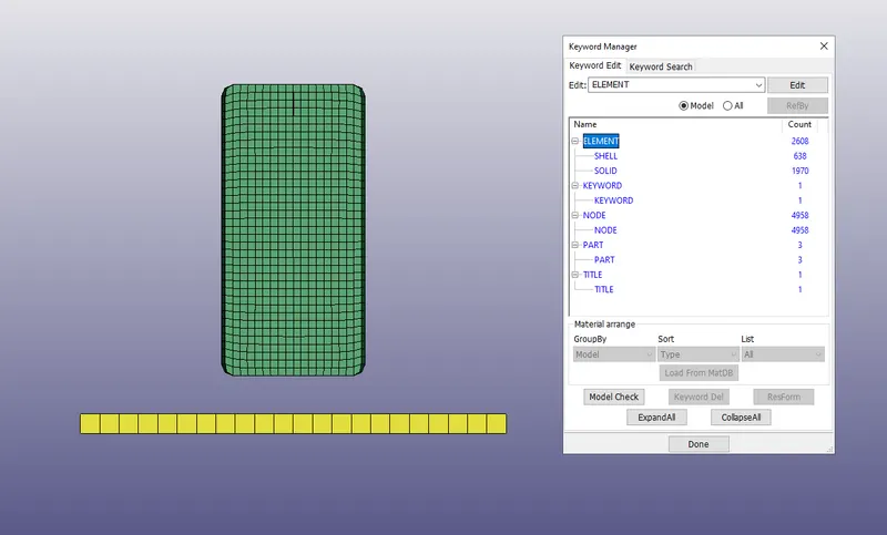
Fig2:
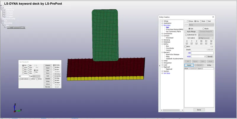
Fig3