Week - 3 Drop test Challenge
Aim: To create a solver deck setup for the Drop-Down case of Cell Phone with required set of results.
Abstract: In this assignment we are going to study the case of Cell Phone Drop simulation. This will be done by setting up the necessary keyword to mimic the actual conditions, we will also assign the initial velocity card and set the required boundary condition to getting the result from the output files (D3 Plots and ASCII files)
METODOLOGY: we need to follow a few steps to setup the deck file
- Import the model as (K. file) as LS Dyna Keyword file
- Build the material card for both cell phone and ground
- Creating a section part for both mobile phone and the ground
- Define the section and material to the Part
- Create a contact interface between the cell phone and the ground plate
- Define a boundary condition to the both cell phone and the ground plate
- Define the initial velocity to the cell phone
- Define the proper control cards and Termination card which are necessary to run the simulation
- Define the output as both binary d3 plot and ASCII
Procedure:
Units to be followed [Kg, mm, ms]
- Import the Ls-Dyna Keyword file by using the open option in LS-Dyna
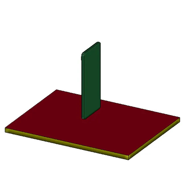
- Go to model and part and checkout the Keywords that contain in the file
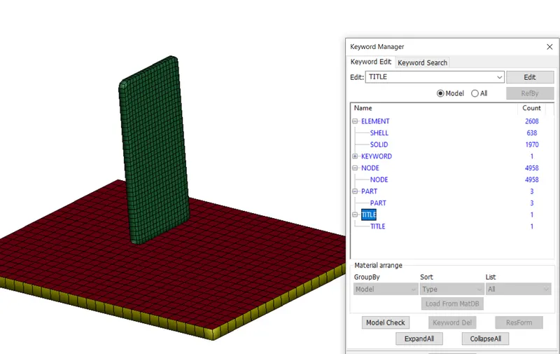
This will give us good idea about what includes in this model
Here we have both shell and solid element present, but for our analysis we have to remove those shell part and also here there is no material and section define for both cell phone body and Ground, so we need to create this and then define to the both Cell Phone and the ground.
- But one thing we find-out from our result is that there is duplicates elements present here, so we need to remove them first and then continue to setup the problem
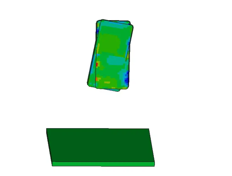
Duplication of elements in solid phone
- To remove the duplicate element, first we need to check about duplicate nodes and then if it is present then merge the duplicate nodes, means one two or three elements belong to the same node, after that you can go to element edit option and then remove those duplicate nodes.
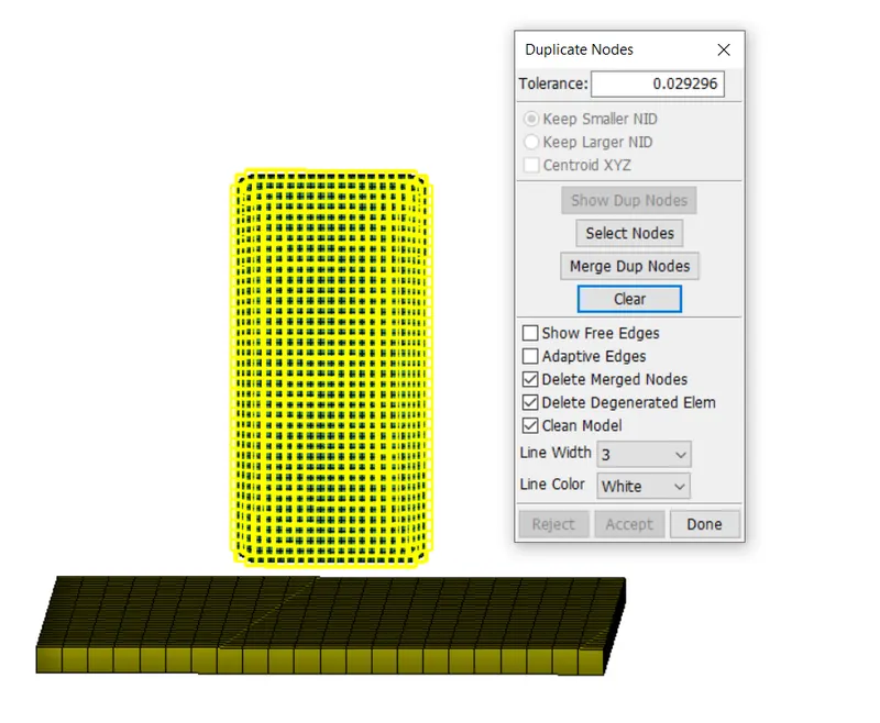
Duplicate nodes and Merging of duplicate nodes
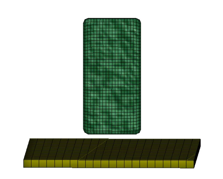
Duplicate nodes after Merged
- Now go to element edit and find-out for duplicate nodes and delete it.
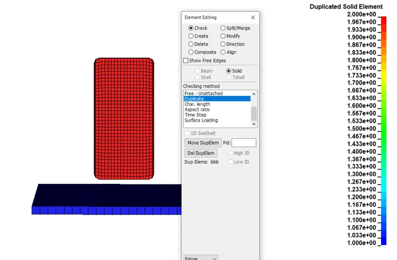
Duplicate solid elements found
- After that just delete these duplicate nodes, now our model is cleaned.
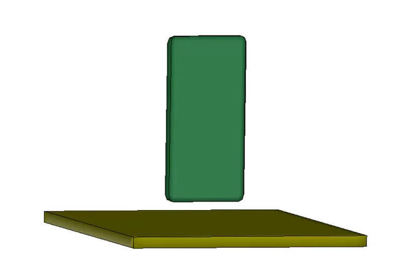
- After that we can start modeling the material for both Cell Phone and ground, firstly we define the material for the cell phone, we take it as aluminum, as aluminum is used for body part of the cell phone.
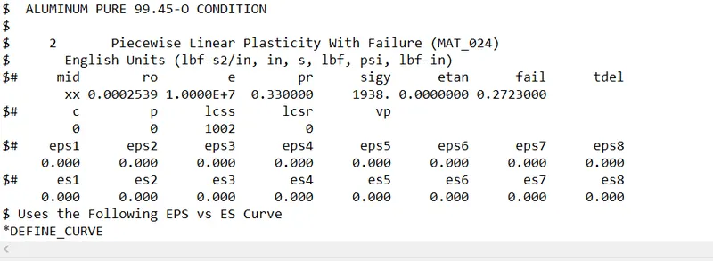
Using pure Aluminum 99.45 – 0 condition
- To define a material, go to Keyword and then go to all, and then go to material to define the material, here we are using the (MAT_024) Piecewise Linear plasticity with Failure card to define the material for the cell phone.
Note: Probably it is recommended that we need to put the data having 1000 points for test, we need to make sure that when we put some raw data in LS-DYNA and if you submit it after you submit, it will give you warning, that data shouldn’t be noisy, all these noise data can lead to numerical instability.
Here we have the stress-strain curve that we can use it to define the material
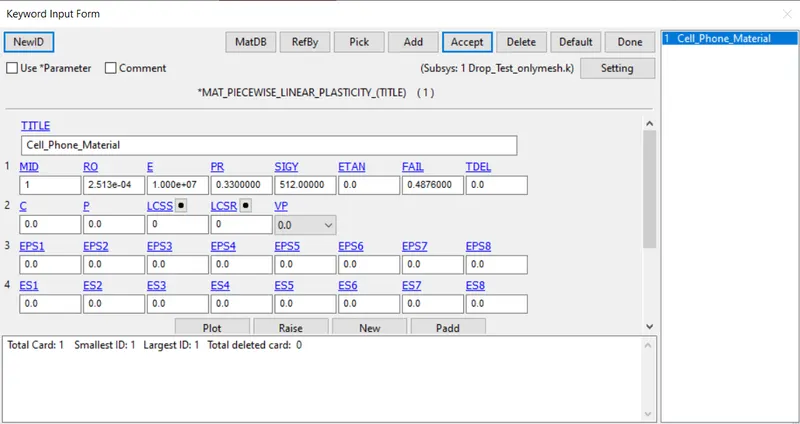
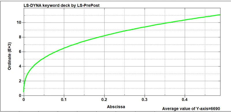
Defining a Plastic portion by using the test data
- Here also we can define those curves, if we have tangent modulus value, but it is better if we have some test data that have large number of points with less noise, and elastic part is define by using the value of E (Elastic Modulus) and pr (Poisons ration) and yield strength of the material, software will automatically calculate or define the elastic portion by itself if we define these values.
- Now we need to define the material for ground, it is quite clear that the ground is much stiffer than the cell phone, obviously we are not interested in the ground, our area of interest is the what happen to the cell phone, if it is dropped out from some height, can it will able to sustain that load or impact, so we define the ground plate as rigid, for that we are using the MAT_RIGID (020) card to define the ground as rigid one.
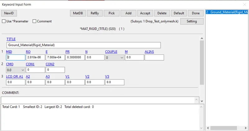
Defining a material for Ground
- After defining the material, now we need to define the section for the material, where we need to define the Element formulation and properties of that element.
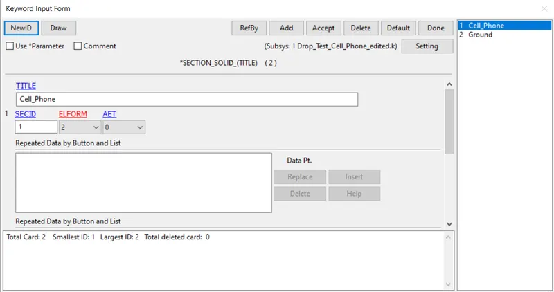
Defining a section for both Cell phone and Ground plate
- After defining the both Section and Material for Ground and cell phone, now next step is to assign them to the both the Cell Phone part and Ground Part
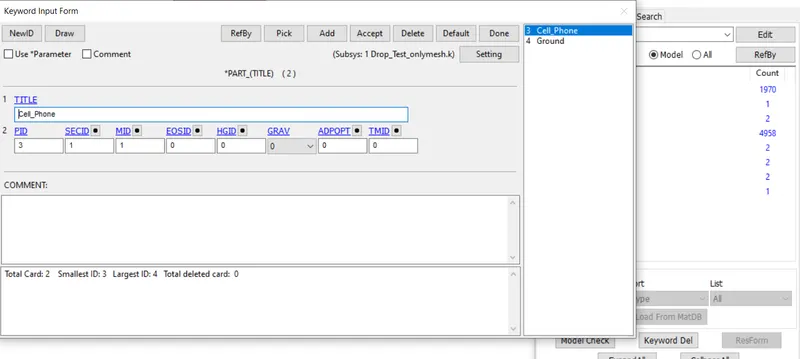
Defining a Section and Material ID to the part
- Now we need to define the boundary condition, boundary condition means we need to constrained the things in space or with respect to cartesian co-ordinate, just like the ground, it is free in space, it had no restriction, so if we left it like that then it will be fall down during our simulation, so we need to fix it in space by restricting their DOF in all x y and z direction.
- But before defining the boundary condition we need to create Node set id that contains all the ground nodes, after that we can proceed to define the boundary condition.
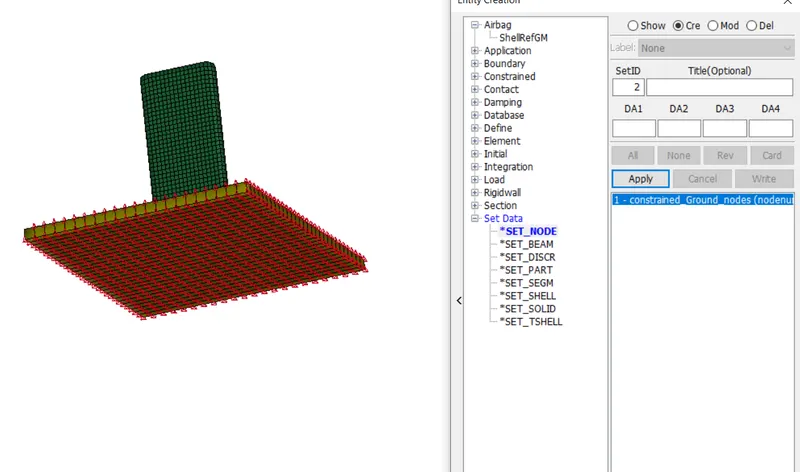
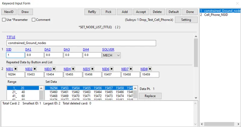
Defining a Node set id for both Ground Nodes and Cell Phone
- After defining the Node set id, now we can define the boundary condition, for that go to Keyword and all and then go to Boundary condition and SPC (Single point constraint), define the Node set id and then lock it’s DOF in x y and z direction, so that it will not move in space during impact.
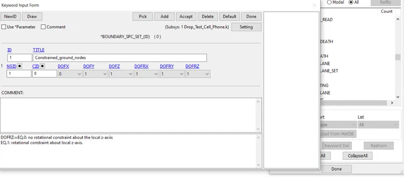
Defining a Boundary condition for ground plate
- For cell phone we need to define the initial velocity in z direction, also we can take or define the gravity effect also, but for that we need to increase its height, but we can give motion it by defining initial velocity to it. Here, we need to give the node set id that we created previously and then we need to define it and also, we need to define the velocity in z direction (- ve side), As we know
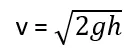
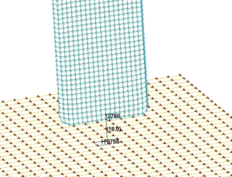
if we take the value from the model then we get 19.8mm, if we put this value in the above formula, we get v = 0.623 mm/ms
But here we are using the MIL-Standard 810G according to this we calculate the velocity where the cell-phone is dropped from the height of 180 cm or 1800 mm, velocity v = 5.929 mm/ms
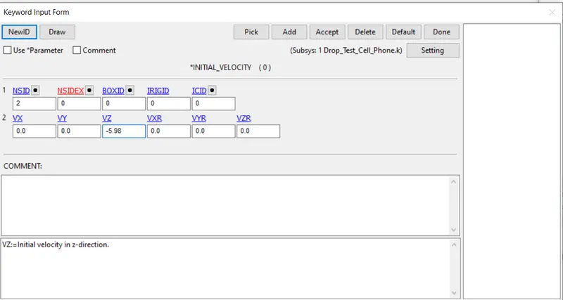
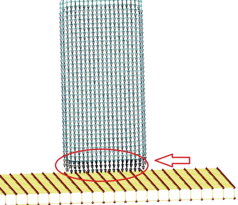
Defining an initial velocity to the cell phone
- After defining the velocity now, we need to define the Contact between the Ground plate and the cell phone, here we are using the surface - surface contact between the cell phone and the ground plate, here we define the master as Ground because ground has stiffer than the cell phone, and defining the slave as cell phone in a contact.
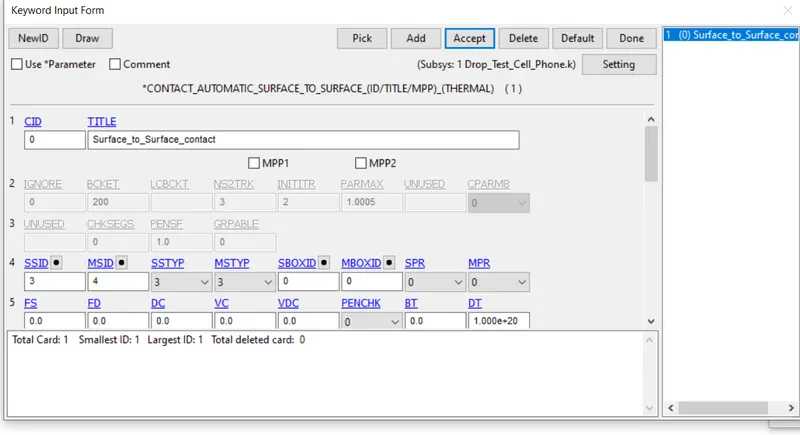
Defining a Surface to Surface contact
- Now we need to define the control keyword like Control energy, Time step and the Termination time, here we define the 40 ms as our termination time.
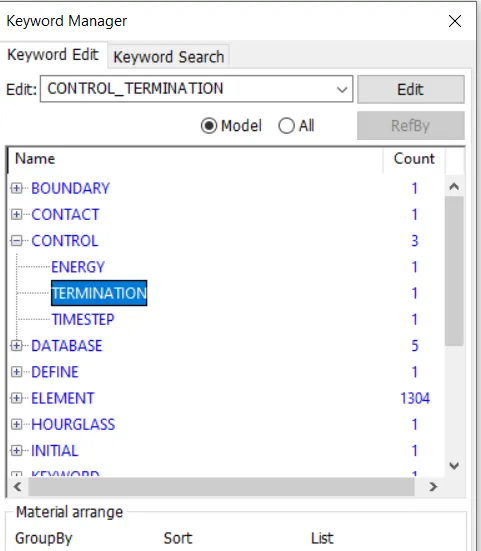
- After defining the control card, the next we need to define the output, for output we define the both Binaryd3 plot and ASCII results like GLSAT, MATSUM, RCFORC (Contact interface force) and SLEOUT (Sliding interface energies) and other important results, and setting output frequency of 1ms
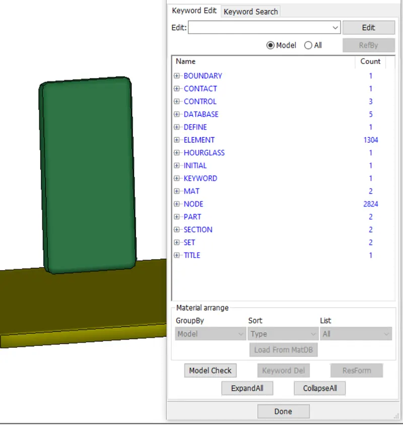
Defining the complete Deck setup for the Drop-Down test
- After that we can save the file, but before that one important thing is to check the error before solving the file, if error is present then file is not able to solved by the solver, so make sure to solve all the error and after that save the file,
- After saving the file, the next step is to open the file in Notepad and edit or give the title and add Keyword ID, because it is a general practice and it is recommended, so that file and their result will not mismatch, otherwise if we don’t follow this then there are more chances of mismatch of results, if you do slightly change in the condition and you don’t know which result or d3 plot belong to which, so it is recommended to give them title and Keyword id so that, our result should coming up with proper name.
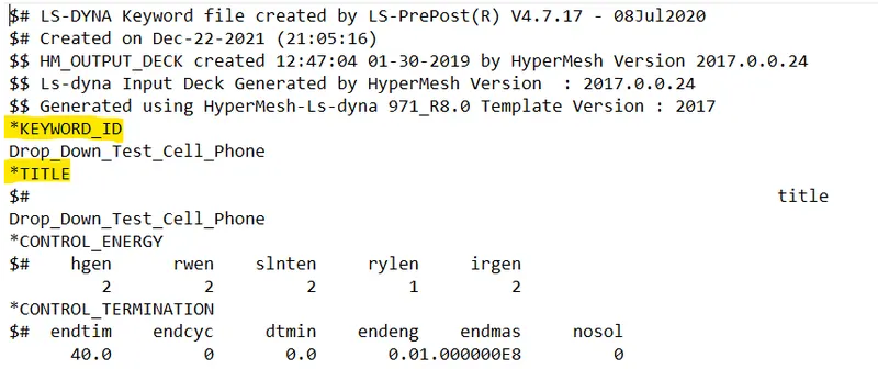
- Now our file is ready for solving. To solve the file open the Ls-Dyna Run and import the file here and then run the file for solving, it will show you how much time it take to solve the file, after solving the file it will gives you result in the form of the input we define like main animation file like Binary d3 plot
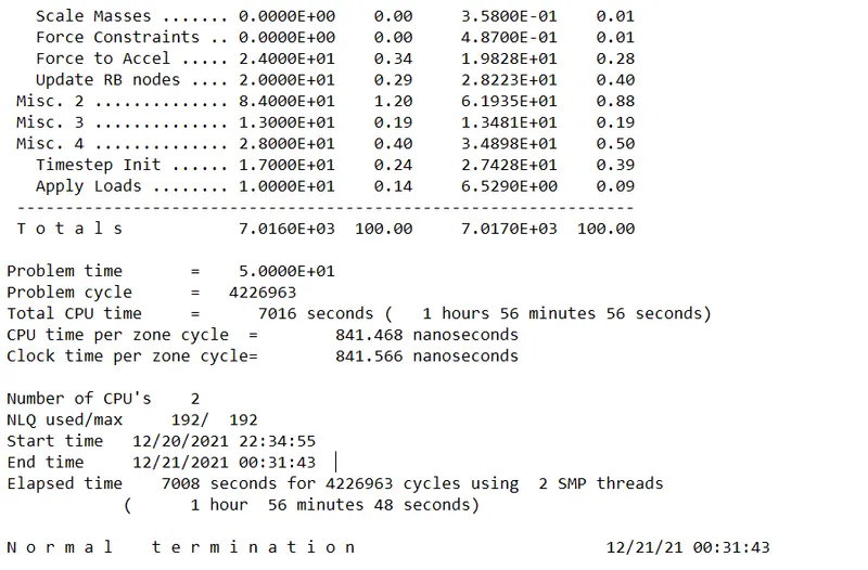
Normal termination (No error while solving the file) which is a good sign for us
- Now we got lot of file in the form of result, but our main file is the d3 plot which is a binary file, we can open it in any editor, but this file is not readable, but we have ASCII file which we can open it in notepad, but it is readable, so we again open the LS-Dyna and then open the dyna binary file in it.
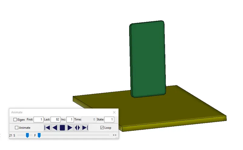
Resultant File is uploaded
- Now to check the result go to Post and then go to fringes option to plot different stresses, displacement and strains
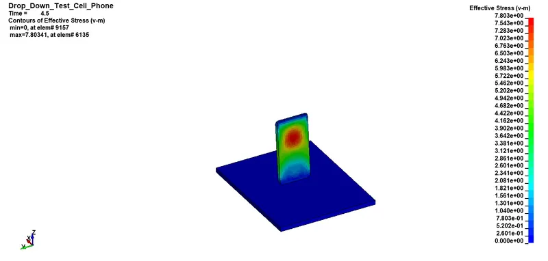
Contour of Effective Von-Misses stress
The maximum value of stress we got is 7.80Gpa as we follow the (Kg mm ms) unit
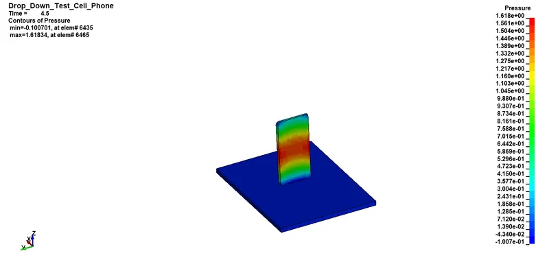
Contour of Pressure
- Now to plot the energy graph, go to History option and select the Energy that you want to plot
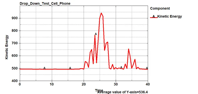
Kinetic energy
- Now as you see here the KE starts deviating when the phone is come in contact with Ground
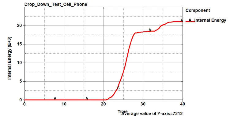
Internal Energy
- As you see here the Internal energy of Cell phone start increasing at 20 ms, at that time cell phone comes in contact with the ground plate.
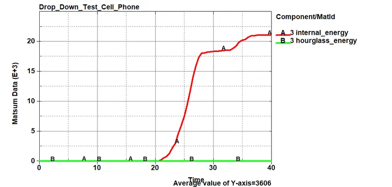
Internal Energy vs Hourglass energy
- Here we got Hourglass energy negligible small and approximately 0 as compare to Internal energy, so there is no Hourglass effect in our model.
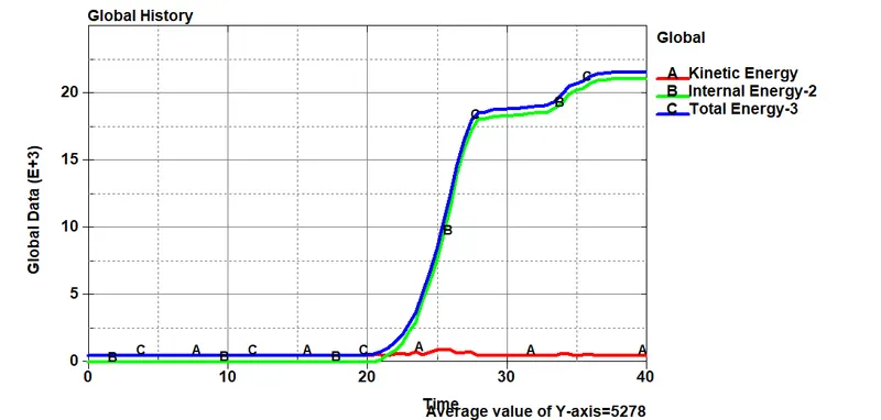
Kinetic energy vs Internal energy vs Total energy
- As you see here the when cell phone comes in contact with the ground the internal energy of the system will increases, as total energy which is the sum of internal energy and Kinetic energy, so as internal energy increases the Total energy also increase with time.
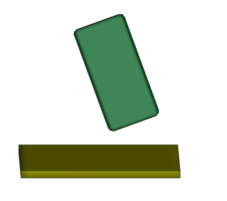
- In similar way we rotate the model in such a way that corner of cell phone comes in contact with the ground
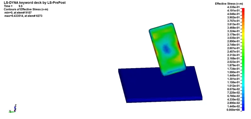
Contour plot of Von-Misses
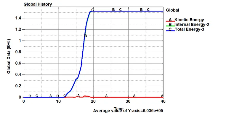
Kinetic energy vs Internal energy vs Total energy
Conclusion: The Deck Setup for the Drop-Down Simulation is Successfully created in LS-DYNA and various results are extracted out from it