Week - 3 Drop test Challenge
Objective:
To perfom a drop test analysis on the given meshed model, by providing a appropriated velocity and boundary conditions using LS dyna software.
- If we accidental drop of mobile phone in daily life is probably the most common failure.Mobile phone is expected to continue functioning after suffering a drop with minimal cosmetic damage. In the last years, work is already done on the mobile phone to develop highly impact tolerant. Several forces and accelerations acts on mobile when it fall, forces depends on the drop height,material, weight, shape orientation at impact surface and several other factor.
- Therefore it is important for designer point of view that what actual facts of drop test on mobile phone at the end of the design stage. Physical drop test may be conduct for feedback to little bit change in product. Inside the assembly of mobile it is also difficult to understand what the component changes taken place. Recently, significant attention and research efforts have been devoted to improve the both board-leveland product-level drop reliabilities of mobile phone.
- Therefore, the interest has turned toward finite element analysis. FEA can conduct starting on the development cycle and helpful in improvement of product. Drop test is also important because of it is less time consuming and less expensive.
LS-DYNA is a general-purpose finite element program capable of simulating complex real world problems. It is used by the automobile, aerospace, construction, military,manufacturing, and bioengineering industries. LS-DYNA combined Implicit/Explicit solver.
Procedure :
Import the model, Ls-prepost - file- open - keyword file
This file contains, Shell as well Solid bodies as shown in below image
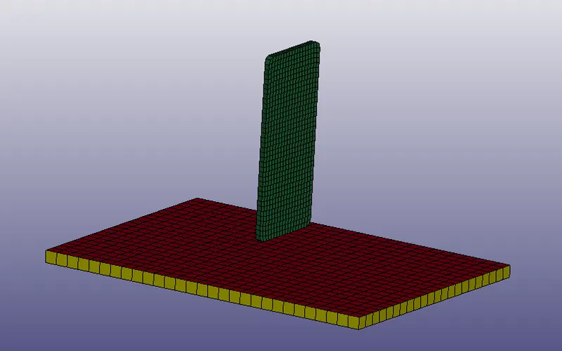
- From the above image, we have shell elements in red color , Rigid Wall (solid element) in yellow color, Cell phone (solid element) in green color
- we will perform simulation on solid Rigid Wall and solid Cell phone
- So we can delete red color sheet part.
- Now create different cards necessary for the simulation.
1.Part:
Now we have only two parts as shown in below image.
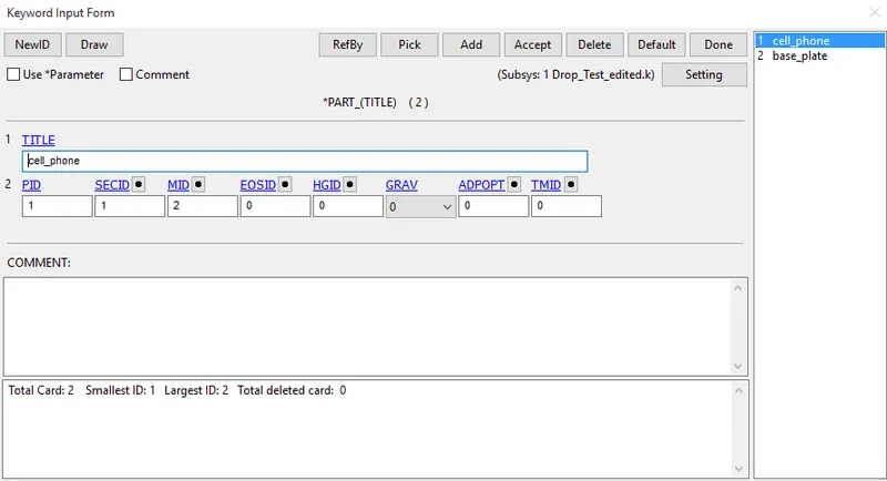
From the above image, first of all give ID , and Title according to part.
2.Boundary:
After creating parts, create boundary condition for rigid wall.
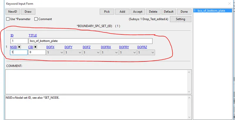
- As shown in above image, we can see that “SPC” single point constraint is created for Rigid Body by selection as a part in “Entity Creation” menu.
- Here all the Degrees Of Freedom have been locked for Rigid Body.
3.Initial Velocity:
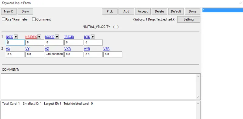
- Here the drop of the Phone will be free fall in z-direction.
- So create Initial velocity from Keyword Manager and give the velocity as -10 in negative z-direction.
4.Section:
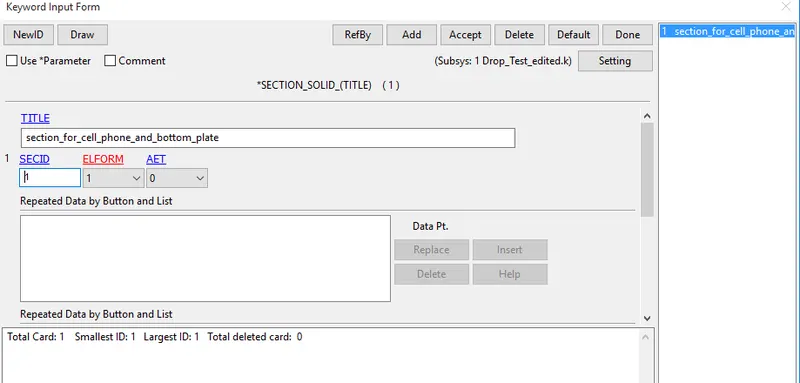
- Here we are working on only solid elements, so create section for solid elements.
- Give title and ID as per convenience.Here Element Formulation is set to 1, Which is default.
5.Material:
- Create material cards for Phone as well as Rigid body as given below.
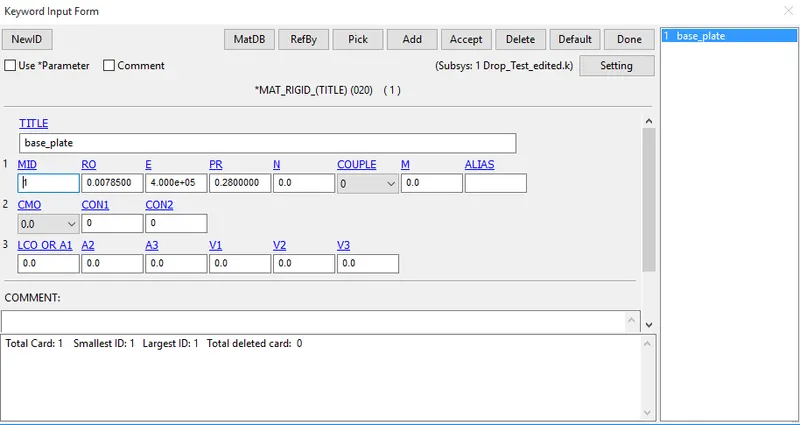
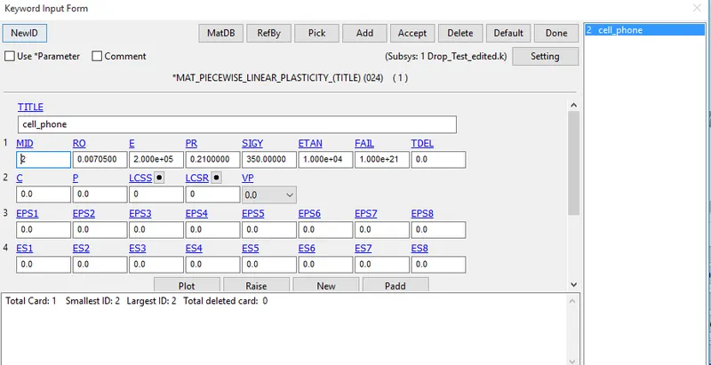
- After creation of section and material cards, we have to apply it to the part. So in Part, assign MID and SECID according to ID’s of Phone and Rigid Wall.
6.Contact:
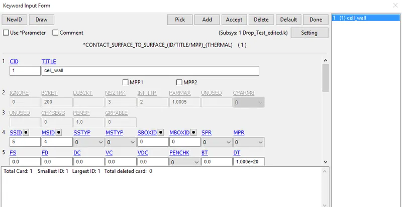
Now for the reaction behavior of the interface, we have to create Contact Interface between Phone and Rigid Wall as given bellow.
- Create “SURFACE_TO_SURFACE” for contact between Phone and Rigid Wall.
7.Control:
After creating all boundary conditions and contacts, create a card for termination.
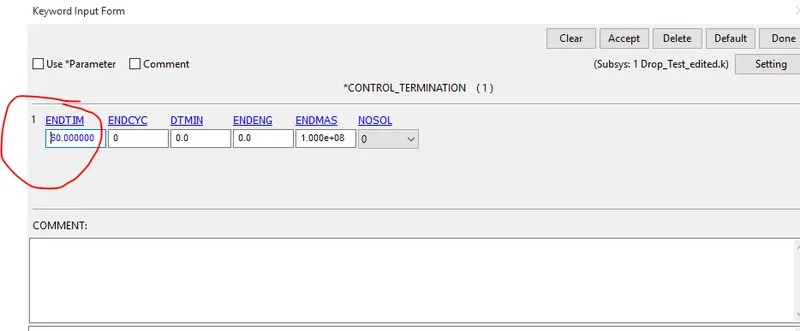
- “CONTROL_TERMINATION”, helps for termination the simulation period.
- By giving “ENDTIM”, up to that value we can run the simulation and then terminate it.
- Here, Termination time is 60.
8.Database:
- Now after all conditions and termination details, we can generate output requests or results what we want from the analysis.
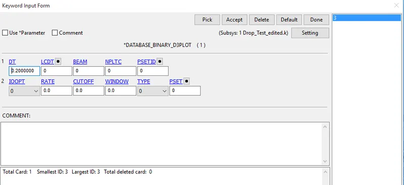
- For that, we have to create cards for output. For animation and other part related data, create “BINARY_D3PLOT”, from database
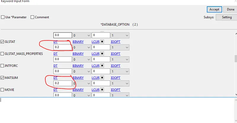
- “GLSTAT”, “MATSUM”, from ASCII_option in database.
- Here we have given the time 0.2 for reporting all the data at each 0.2ms from 0 to 60ms for the accuracy.
Total keywords required to build this model
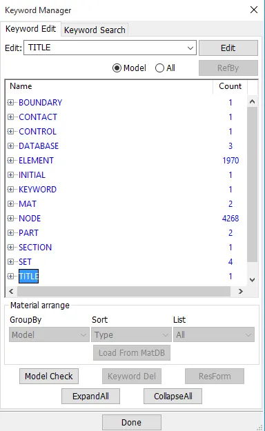
- After creation of keywords, do model check to any error in the model
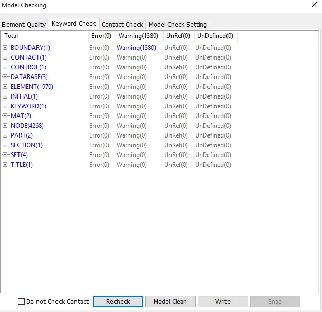
- from the above picture, there is no errors in the model including contacts.
- After creation of all necessary cards, save the Keyword file with “.K” extension.
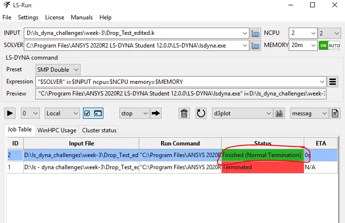
- Run the simulation using Ls - run, Make sure that Termination is Normal .
Results:
Open the Binary “d3plot” file in LS-PrePost and check the results.
Effective Von-mises Stress:
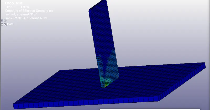
- Max stress generated when cell_phones hits the base plate
- max stress generated in element #6359 at 1.996ms
Displacement:
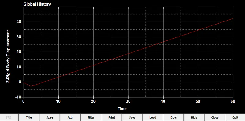
- cell_phone travells from it's initial condition zero (0) to -0.3mm in Z-direction before hitting the plate
- After hitting the plate cell_phone travells from-0.3mm to 40.3mm in Z-direction
Kinetic energy:
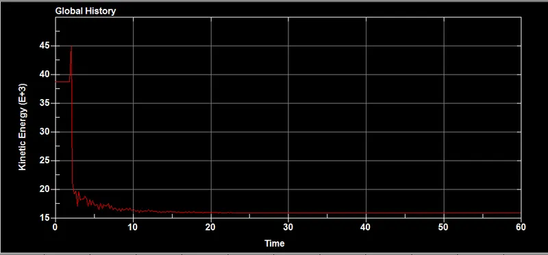
- When phone hits the plate at 2ms it reaches max value 45, after that it reduceses .
- After 15ms the kinetc energy of the phone remains constant throughout the simulation.
Internal energy:
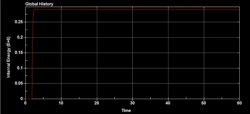
- Internal energy increses upto phone hits the base plate, after hitting the plate at 2ms Internal energy remains constant throughout the simulation.
- Internal energy is inversely proportional to kinetc energy.
Stress for element #6359
In Ls-dyna, we can plot energies, stresss, displacements for an element level
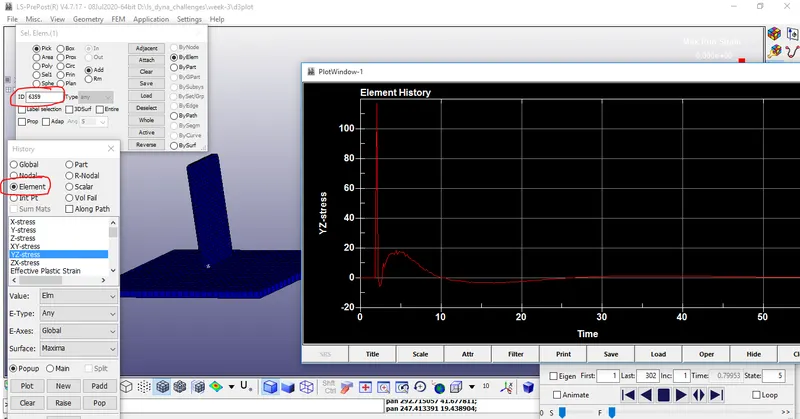
- in the above picture, we plot a stress vs time graph for an element of #6359.
ASCII output graphs
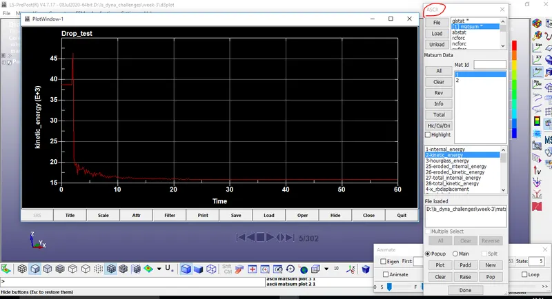
- matsum - it means material energies data (on a part basis)
- ploted a kinetc energy graph for matsum 1.
Conclusion
- Performed a complete simulation of a drop test for cell_phone and base_plate, from a given meshed modal.
- Requested for different outputs and plotted necessary graphs.
- The objective of this assignment is creating an input deck from scratch and we did it sucessefully