Week - 3 Drop test Challenge
Drop Test
Aim
To perform a simple drop test simulation on the given model
Objective
To create all the necessary keyword files for a basic simulation in ls Dyna
Theory
Element Formulation
Element formulation deals with derivations needed to deduce displacements acting on a body when discretized by finite elements. Different formulations apply for different types of elements. Derivation of such displacements is dependent on shape functions.
In LS-Dyna, there are several options for the type of Element Formulation used for analysis given below
Procedure
- On opening the model in Ls pre-post, it can be seen that the floor is covered by a shell and solid part.
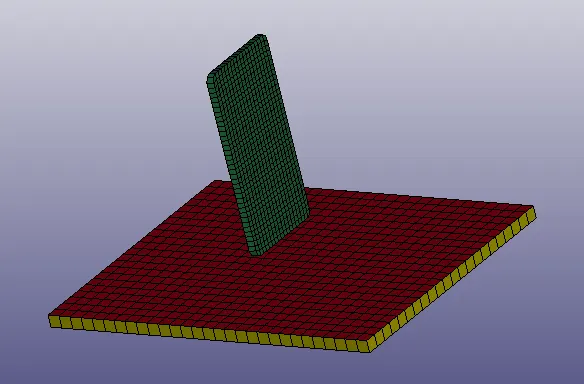
- For our simulation, it is fine to delete the shell part and rename the parts to rigid and phone.
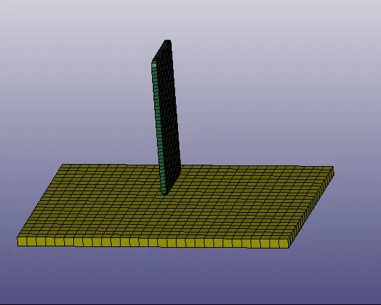
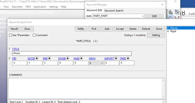
- Make the changes to the name using keyword manager
Boundary Condition
- The boundary condition is to make the floor rigid, that is it needs to be fully constrained.
- This can be done by creating an SPC with all axis constrained using create entity
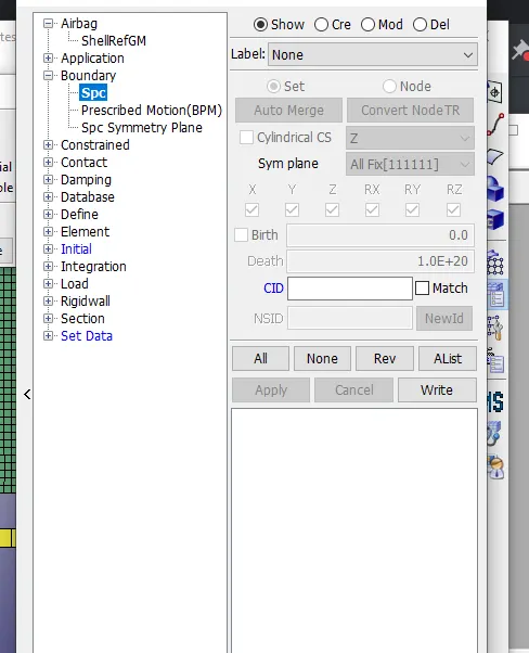
- Alternatively, you can assign the rigid material card and assign it to the part.
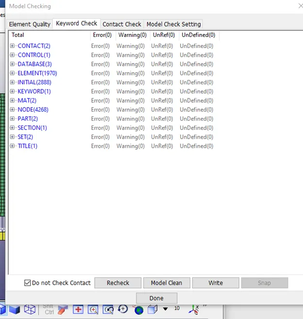
- Note: doing both will result in a warning in the model checker.
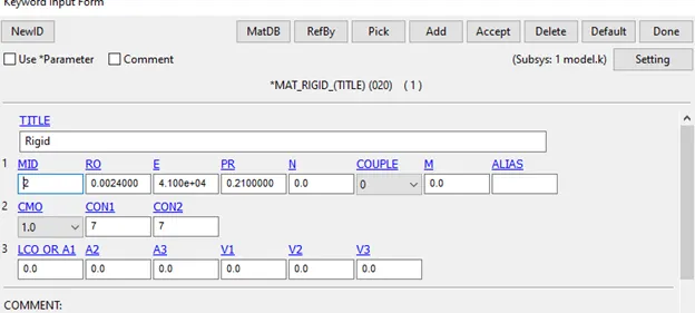
- ConN1 and N2 constrain the translational and rotational degrees of freedom respectively.
Initial Velocity
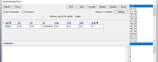
- In, create entity, go to initial and assign an approximate velocity of 0.6mm/ms to the phone.
- Use the select by part option and select the phone.
Material Property
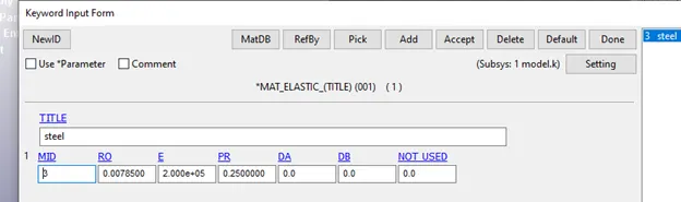
- Create an elastic property card for the phone.
- You can alternatively use linear plastic,mat24, as well but it is necessary to define the tangent modulus properly.
- Assign the values appropriately and then assign the material id to the part
Element Formulation
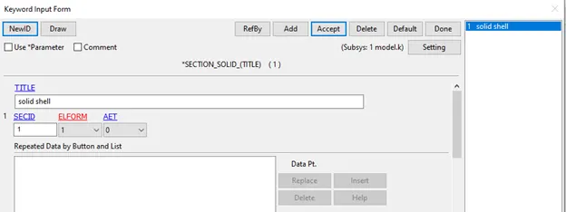
- Since we only have solid elements, we need to only create element formulation for solid elements. We use reduced integrated elements for this.
Contact
- We will create 2 contacts for this test.
- One is a single surface contact for self contact and the other for the contact with the phone and the floor.
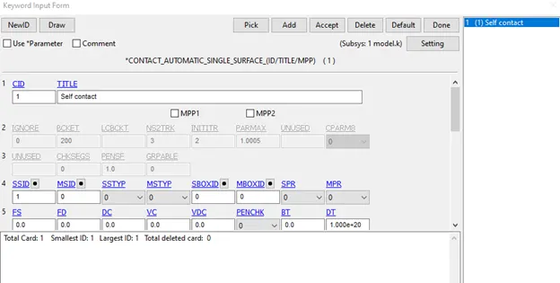
- Don’t create a master node set for self contact.
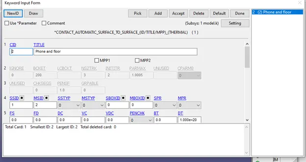
- For the surface to surface contact, the floor is the master and the phone is the slave.
Control Card and Output Cards
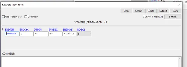
- Create a control termination card and set it to 50ms
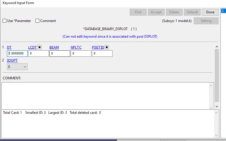
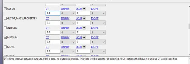
- In Database create a D3plot card and Ascii options
- Run the model checker.
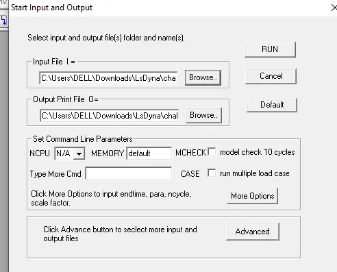
It is fine to run the model on the ls Dyna solver.
Post Processing
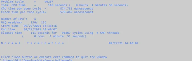
It is important to verify that the termination is normal, anything else indicates that something has gone wrong
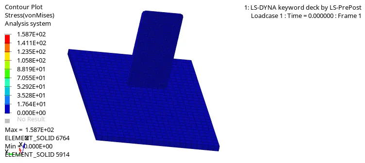
At around 32 ms, the phone impacts the floor and bounces upwards. The maximum stress experienced is 1.58 * 10^2Mpa at the tip of the phone. This could be due to improper force distribution due to the lack of contact control keywords leading to negative contact energy.
Energy Graphs
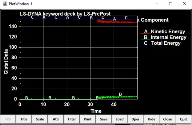
The internal energy is colinear with total energy until the point of impact at around 33ms
At that point, you can see the kinetic energy spikes and the internal energy has a small dip and after that, it varies due to the vibration of elements
The kinetic energy then later is converted into internal energy at a point after the simulation.
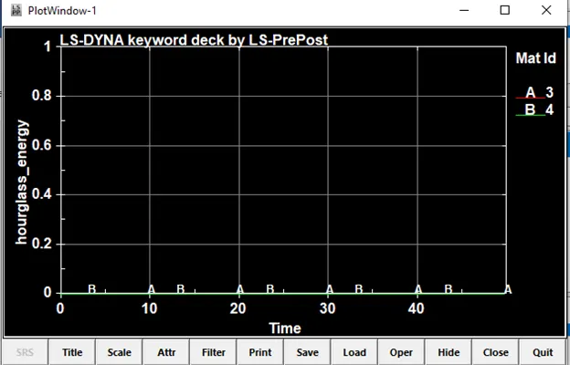
As we are using reduced integrated elements and there are only 3D mesh elements, there is no hourglass energy formation.
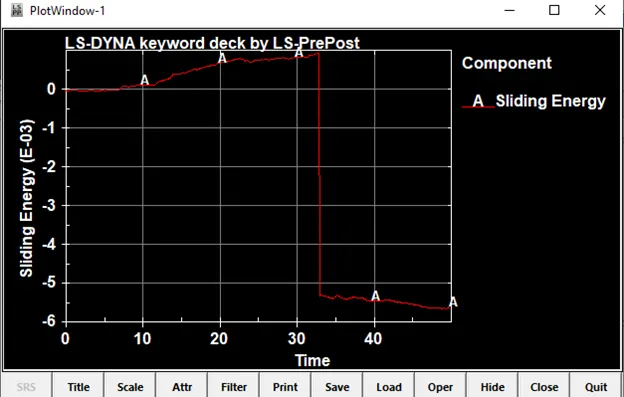
Abrupt increases in negative contact energy may be caused by undetected initial penetrations at the point of impact at around 33 ms.
Negative contact energy sometimes is generated when parts slide relative to each other. When a penetrated node slides from its original master segment to an adjacent though unconnected master segment and penetration is immediately detected, negative contact energy is the result.
Some general suggestions for combating negative contact energy are as follows:
- Eliminate initial penetrations (look for Warning in message file).
- Check for and eliminate redundant contact conditions. You should NOT have more than one contact definition treating contact between the same two parts or surfaces.
- Reduce the time step scale factor.
- Set contact controls back to default except set SOFT=1 and IGNORE=2 (Optional Card C).
- For the contact of sharp-edged surfaces, set SOFT=2 on Optional Card A. SOFT=2 is also referred to as segment-based contact and so does not apply to any NODE_TO_SURFACE type contacts. Two important companion variables to SOFT=2 are SBOPT and DEPTH. Two important companion variables to SOFT=2 are SBOPT and DEPTH.
SBOPT: Unless sliding between surfaces is prevalent, set SBOPT=3. When sliding is prevalent, set SBOPT=5.
DEPTH: DEPTH=13 or 23 is recommended unless shell edge-to-edge contact must be considered, in which case set DEPTH=25 or 35.
Please note that SOFT=2 contact carries some additional expense as compared to SOFT=0 or 1,
particularly using non-default values of SBOPT or DEPTH.
Learning Outcomes
- Setting a basic simulation in Ls Dyna
- Creating keywords and boundary conditions
- Plotting Graphs in Ls pre-post
Conclusion
The given drop test model was run successfully. There was negative contact energy at the point of impact indicating initial penetrations taking place at the impact. This can be rectified using *Control_contact settings. Make sure you set IGNORE in *Control_Contact to 1 or 2, which ignores initial penetrations. By default, this is 0 which will cause dyna to move the mesh to avoid these, which might cause weird energy in the simulation.