Week - 4 - 2D meshing for Plastic components
WEEK 4 CHALLENGE
AIM
To generate the mid surface of the given model and generate a mesh according to the required quality criteria.
PROCEDURE
- Geometry cleanup is performed on the after which we can move on to generating the mid surface.
- The thickness of each part is measured and then stored.
- For midsurface generation, manual midsurfacing was followed.The offset command was used with the feature area selection option for entity selection.
- Its observed that certain parts like the outer ribs have varying thickness,For such parts we will use the middle option to generate the mid surface.
- Other parts such as the top bar or the inner attachment may be split into different Property Ids.
- The below table shows the thickness of each Part Id.
|
Part Id |
Thickness(mm) |
|
Outer Shell |
1.22 |
|
Inner Shell |
1.04 |
|
Inner Shell 2 |
1.13 |
|
Top Shell |
1.53 |
|
Outer Ribs |
0.4 |
|
Thread 1 |
0.893 |
|
Thread2 |
0.825 |
|
PShell |
1.2038 |
|
Inner Attachment t1 |
0.8093 |
|
Inner Attachment t3 |
0.5032 |
|
Inner Attachment t2 |
0.65625 |
|
Top Bar t1 |
1.53 |
|
Top Bar t2 |
1.279 |
|
Top Bar t3 |
1.028 |
|
Triangle attachment |
1.22 |
|
Mid Teeth |
0.6099 |
|
Teeth Surface |
0.85978 |
|
Pshell 2 |
1.785 |
|
P shell 3 |
0.3694 |
- Check Geometry is performed to check for geometrical errors such as collapsed cons,
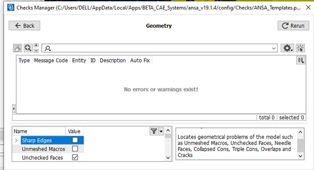
Figure 1.
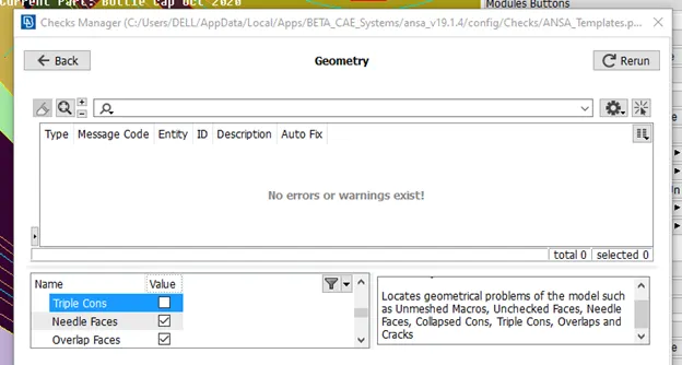
Figure 2
- Certain features like the outer ribs and inner attachments need to be extended properly so that the generated mid surface will be accurate.The resulting triple cons formed are considered acceptable.
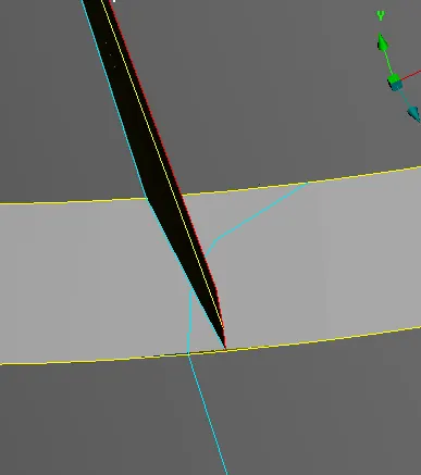
Figure 3
- Parts like the teeth are generated using the curve middle and new face option after which we transform rotate them to save a significant point.
- To transform rotate we need 2 points in the centre at varying heights for which we use the points cog option. Using the generated points as the centre we can rotate the feature properly.
- Using the cut and join option we remove unnecessary double cons from the mid surface for meshing simplicity.
- It can be noted that if the features such as the ribs were split into different Pids so as to capture the mid surface more accurately.
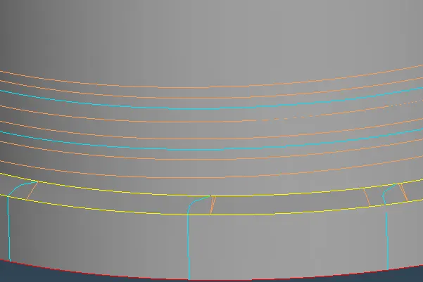
Figure 4
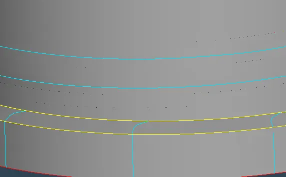
Figure 5
The below images show the generated mid surface
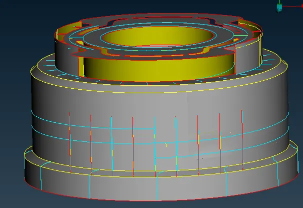
Figure 6
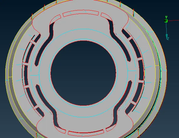
Figure 7
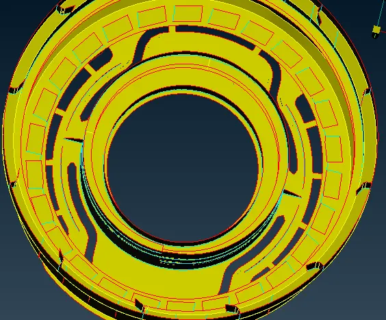
Figure 8
MESHING
- After topology clean up, we can move on to meshing the mid surface.
Figure 12
- First, we set the meshing criteria according to our requirements.
The criteria are given in table 2
|
Criteria |
Value |
|
Element Length |
1mm |
|
Minimum length |
0.5 mm |
|
Maximum Length |
3 mm |
|
Aspect Ratio |
3 |
|
Warping |
15 |
|
Skewness |
45 |
|
Jacobian |
0.7 |
|
Min angle Quad |
45 |
|
Max angle Quad |
135 |
|
Min Angle for tria |
30 |
|
Max angle for tria |
120 |
|
Tria percentage |
15 |
- We set the criteria accordingly in the mesh parameters tab and quality criteria tab and also enable elements % and set the details to max.
- Using the length command we set the length to 1mm so that the element length across the mid surface will be 1 mm.
- Now we move on to meshing, we use the best mesh option under mesh generation for this.
- We may choose to mesh each Pid separately for simplicity and then solve their errors separately.
- It should be noted that the errors near triple cons are left as is due to them not being solvable and are considered acceptable.
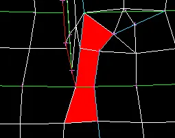
Figure 9
- The mesh is reconstructed/smoothed so as to solve the failed elements and reduce tria percentage.
- After this we now manually look at the mesh and look for opposing trias and rotating quads to solve using split,join and reconstruct
- Figure 18-20 show the final meshed model.
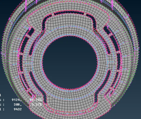
Figure 10
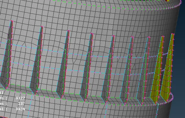
Figure 11
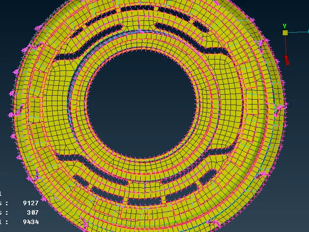
Figure 12
- After final mesh editing is done,Enable draw shell as solid option in the presentation parameters in quality criteria.
- Now we enable the parent geometry,set transparency on and compare the mid surface to verify its accuracy.
- The final elemen % is show in figure 13.
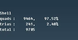
Figure 13
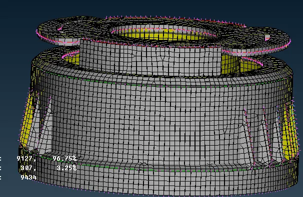
Figure 14
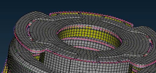
Figure 15
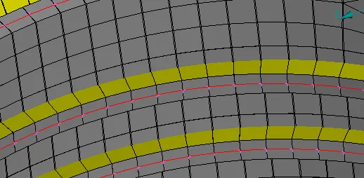
Figure 16
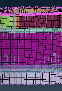
Figure 17
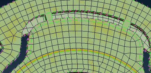
Figure 18
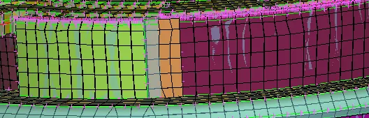
Figure 19
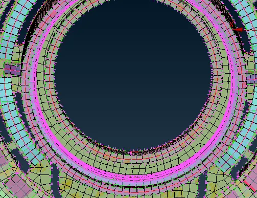
Figure 20
Learning Outcomes
The following skills were learnt and practiced during this challenge.
- Model Geometry Clean up
- Mid surface Generation (Manual and automatic)
- Mid Surface topology clean up
- Mid surface Defeaturing
- Using new face and extent command to get a better mid surface for features.
- Setting up Mesh quality criteria
- Generating Mesh with best mesh criteria option
- Modifying Generated mesh to fix elements that fail the criteria along with opposite trias and rotating quads.
- Drawing the generated mesh as a shell.
Conclusion
The meshing of the given Plastic Bottle Cap model was performed following strict standards which were passed.After topology clean up, the generated mesh was modified to correct element failures and remove rotating quads and opposite trias.Trias near the edges were changed to quads or moved away from the corner using various commands such as split , swap and join.