Week 3 - 2D meshing for sheet metal
WEEK 3 CHALLENGE
AIM
To generate the mid surface of the given model and generate a mesh according to the required quality criteria.
PROCEDURE
- Geometry cleanup is performed on each part to check for triple cons, single cons, cracks, unchecked faces, etc after which we can move on to generating the mid surface.
- Measure the thickness of each part and store the measurements.
- For a mid surface generation, we will generate it individually for each surface for simplicity. This can be done by hiding/suppressing the other parts appropriately.
- The below table shows the thickness of each part.
|
Part |
Thickness(mm) |
|
Part 1 |
0.75 |
|
Part 2 |
0.75 |
|
Part 3 |
1.2 |
|
Part 4 |
1.2 |
|
Part 5 |
1.2 |
- Figure 1 to Figure 5 show the different parts required to be meshed
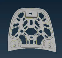
Figure 1.
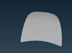
Figure 2.
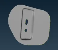
Figure 3
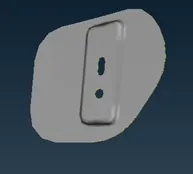
Figure 4
Figure 5
- For mid surface generation, manual mid surfacing was followed. The offset command was used with the feature area selection option for entity selection.
- Certain areas had very small thickness which would fail for element quality criteria, refer to figure 6. The join and cut command under the topo module were used to eliminate such areas which will otherwise fail during meshing.
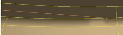
Figure 6
- In part 2, In the hemming region(in the Outer panel’s bend region), Elements will fail for the Min length error due to the very small surface to capture the curved surface. To solve this defeaturing of the surface was followed and the peak of the fillet was captured while following minimum element criteria.
- Figure 7 to figure 11 show the mid surface of the parts after topo clean up.
The pink cons refer to the joined cons during topo clean up.
After clean up, separate Property Ids were set to each mid surface using the set PID command after which we move on to the mesh module.
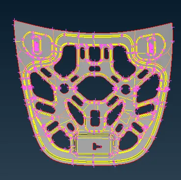
Figure 7
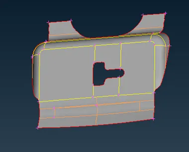
Figure 8
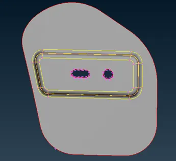
Figure 9
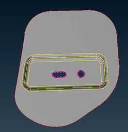
Figure 10
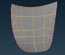
Figure 11
MESHING
- After topology clean up, we move on to meshing the mid surface.
- Using the number command we make sure that the number of edges on each hole is an even number which gives a better mesh result. The edges of such holes should be parallel to the nearest edge for the best mesh result using the slide command after which we mark the points of the hole. Figure 12 shows one such example.
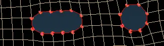
Figure 12
- First, we set the meshing criteria according to our requirements.
The criteria are given in table 2
|
Criteria |
Value |
|
Element Length |
5 mm |
|
Minimum length |
2 mm |
|
Maximum Length |
7 mm |
|
Aspect Ratio |
3 |
|
Warping |
15 |
|
Skewness |
35 |
|
Jacobian |
0.7 |
|
Min angle Quad |
45 |
|
Max angle Quad |
135 |
|
Min Angle for tria |
30 |
|
Max angle for tria |
120 |
|
Tria percentage |
15 |
- We set the criteria accordingly in the mesh parameters tab and quality criteria tab and also enable elements % and set the details to the max.
- Now we move on to meshing, we use the best mesh option under mesh generation for this.
- Splitting the part into sections will give us better mesh flow and mesh quality as shown in figure 13.
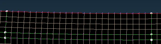
Figure 13
- After mesh generation, we enable shadow mode to check for elements that fail the quality criteria.
- These failed elements can be modified by various commands such as reconstruction, smooth, split, join,num+-(modifies the number of edges on the surface)
- Rotating quads and Opposite trias present in the model should be eliminated for better mesh result. Trias near to free edge or holes or on the fillets should be eliminated.
- This can be done via reconstructing, smooth, split, join, swap commands.
- Figure 14 – 18 shows the parts after meshing.
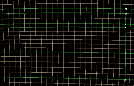
Figure 14
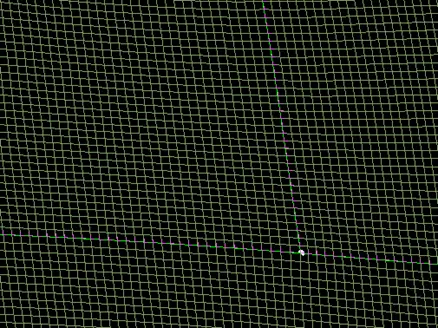
Figure 15

Figure 16
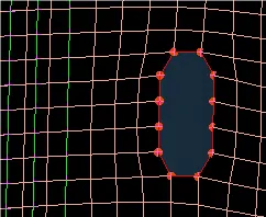
Figure 17
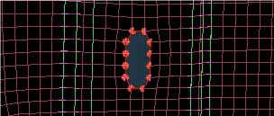
Figure 18
- After final mesh editing is done, Enable draw shell as a solid option in the presentation parameters in quality criteria.
- The final meshed part is shown in figure 19-23.
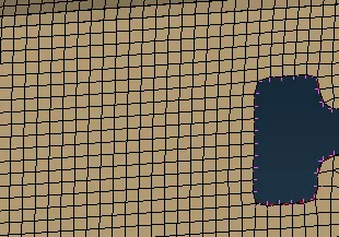
Figure 19
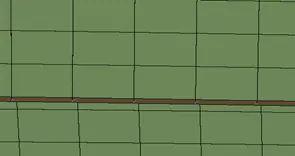
Figure 20
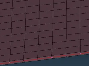
Figure 21
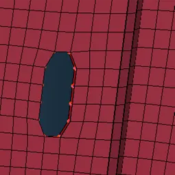
Figure 22
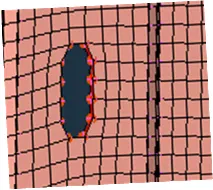
Figure 23
Learning Outcomes
The following skills were learnt and practised during this challenge.
- Model Geometry Clean up
- Mid surface Generation (Manual and automatic)
- Mid Surface topology clean up
- Mid surface Defeaturing
- Setting up Mesh quality criteria
- Generating Mesh with best mesh criteria option
- Modifying Generated mesh to fix elements that fail the criteria along with opposite trias and rotating quads.
- Drawing the generated mesh as a shell.
Conclusion
The meshing of the given hood model was performed following strict standards which were passed. After topology clean up, the generated mesh was modified to correct element failures and remove rotating quads and opposite trias.
Trias near the edges were changed to quads or moved away from the corner using various commands such as split, swap and join.