Week - 3 Drop test Challenge
Objective
The objective of the challenge is to create a deck and run the simulation for the cellphone drop model provided.
Procedure:
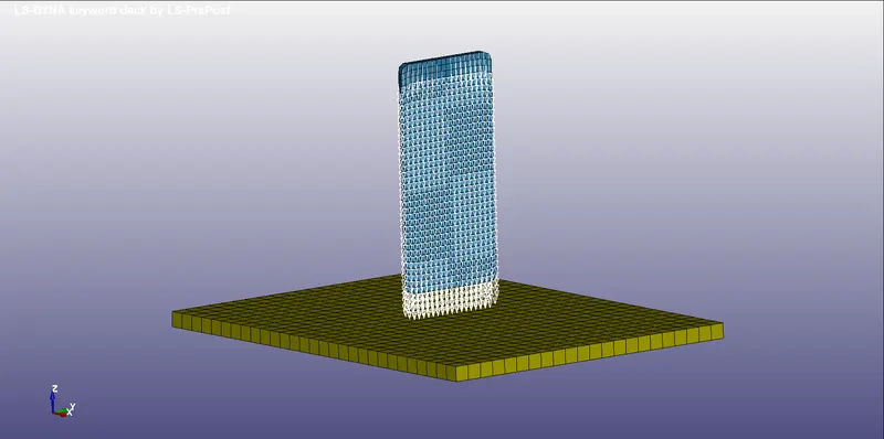
- once the model is opened in LS Dyna, one can see three components present, they are: Shell Surface, Solid Base elements and the cellphone meshed model. the base and the cellphone are created with 3D elements.
- As ususal, the work begins with creating Mat and Sections. For the base, MAT_5 is used which is nothing but Soil and Foam, predominantly used to replicate concrete. Here, the base is considered as a separate material called concrete.
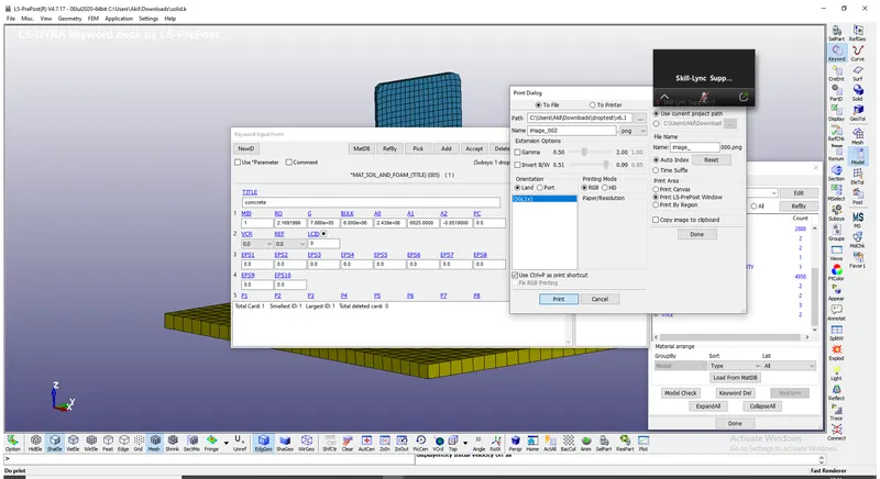
- The mat_5 requires density, shear modulus, bulk modulus and yield of the material. If the shear and bulk modulus are low, there happens to get a different result, which we will see in the Error section of the report. The concrete mat data is taken from the dynasupport website where it was readily available. So values are inputted in the MAT_5 card.
- For the mobile, a steel material is inputted for reducing the complexity.
- Once this is set, element formulations for the 3D elements are created. The ELFORM selected is 2 which is Fully integrated solid element formulation. This does not create any hourglass in the elements.
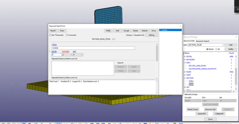
- Both there SEC and MAT are inputted in the PART keyword for both the components. The third component, which is a shell, is actually deleted due to a particular reason with respect to material which in turn we will discuss in the Error section.
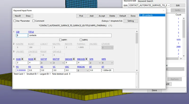
- Contacts: The mobile is being dropped onto the base, where the mobile and the base comes in contact with each other. This elements coming together is made possible by the Automatic Surface to surface contact, The automatic surface to surface contact even if the master and slave is inputted, while assembling the stiffness matrix, whichever component has less stiffness it will take that as the slave and not the other way around. This makes it much more easier to work with.
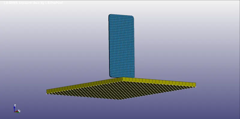
- SPC: Single point constraint needed to be assigned to the base as it must be fixed in space. BOUNDARY_SPC from the 'create entity' window is used and selected only the base nodes to fix the base model. If the top nodes are selected, then the material data provided to the base concrete becomes insignificant.
- LOAD CONDITIONS: For this, initial velocity is provided, using INTIAL > VELOCITY keyword. A value of 15 mm/ms is provided as the gap between the mobile and the base is around 20 mm.
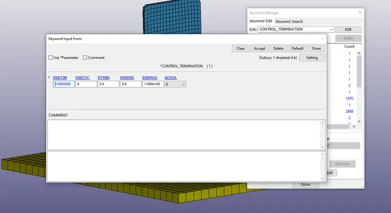
- TERMINATION Time: A termination value of 3 ms is provided to look the entire effect of dropping and its after effects.
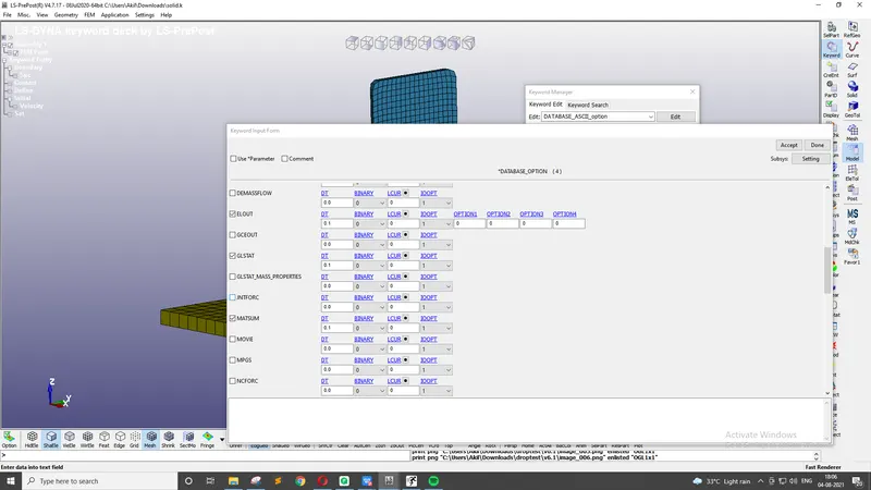
- *DATABASE keyword is used to create binary plot and also ascii outputs. It is important that the global DT of 0.1 is inputted only then the model's energies are recorded and glstat and matsum files are created.
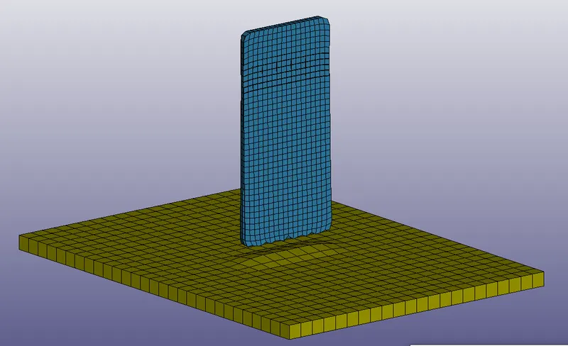
- Model checker is carried out for final checks and the simulation is solved. Attaching below the gif of the final output that produced.
Errors Experienced
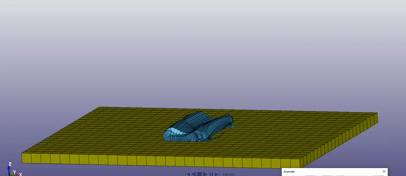
1. Load Curve vs INITIAL boundary conditions: If the velocity is inputted as Load curve, it acts as IMPVEL where what ever the disturbance is the load will be keeping on adding till the end of the simulation time. When this happens the mobile model completely crushes like a can being crushed like shown below, hence this is completely wrong.
2. MAT_5 material card is applicable only for the solid elements and not for shell elements. If the simulation is carried out then you get the error.
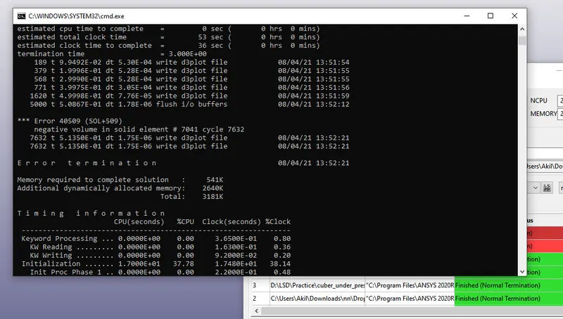
3. If the inputted material has incorrect values, then this kind of the negative volume error occurs in the model, which needs to be taken care of. Negative volume can be better removed through using proper material card.
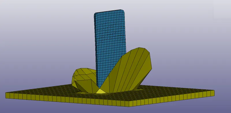
4. If the concrete's bulk modulus value is very less then this kind of output is very much expected.
Conclusion
The given model is simulated and the outputs are obtained, Also the errors that the user experienced are also mentioned in the report.