Week - 3 Drop test Challenge
AIM:
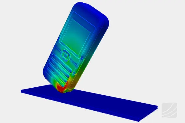
To perform the simulation of a cell phone drop test using LS-DYNA with required conditions and plot the respective results.
DROP TEST :
A drop test is a test designed to examine the structural integrity of a product.Drop tests usually involve an object being dropped from a predefined height onto a second object or surface. The object being tested can be either the dropped object or the object/surface that an object is being dropped on to.It is also called as the "Shock test" since the crash frame has to absorb the suddenly applied shock load during the free fall. Only the crash frame which passes the certification after the drop test would go to the market for the actual use.
PROCEDURE :
The given file consists of only the basic mesh file with solid and shell elements. The given .k file is opened in the LS-prepost. LS-prepost >> File >> Open >> Open the binary file.
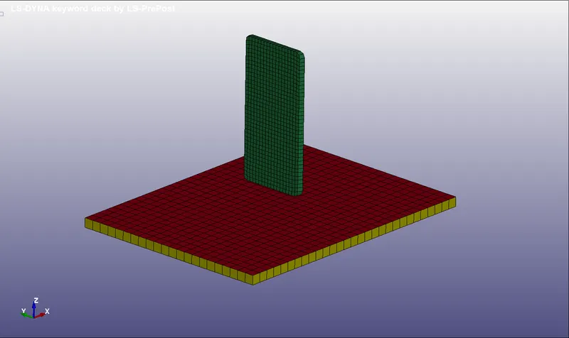
As we can see that there are three different parts in which two were solid elements and the other is shell element. We can have either of them. So, delete the shell elements and keep the solid elements which depicts one as cell phone and the other as the rigid floor. Here is the model after shell element deletion:
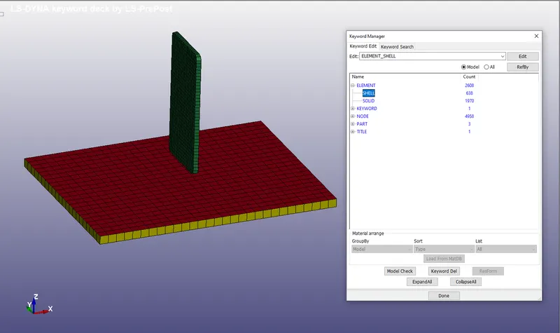
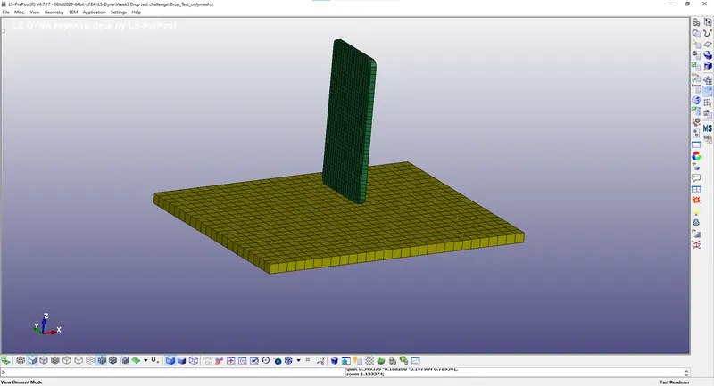
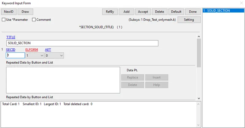
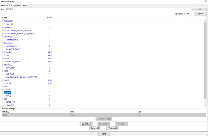
Now, that we have only the solid elements, we can create the section for the solid element. Go to Model and part >> Keyword Manager >> All >> Section >> Solid. Enter the appropriate parameters and provide Section ID and title. Then click accept and done to create the Sections.
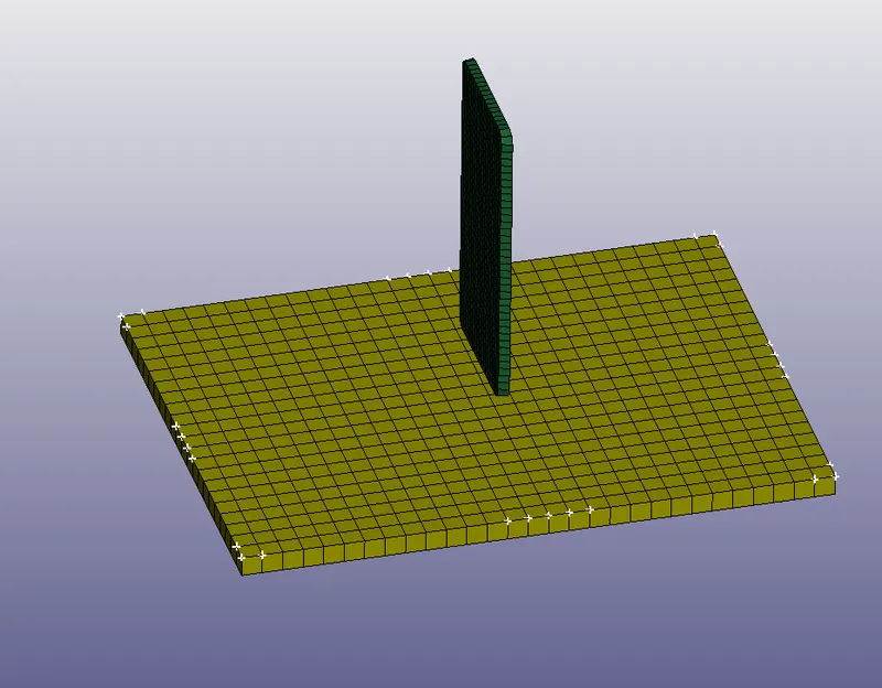
Then, we should provide the boundary conditions to the model. Here we need to think about the real time event. We are trying to simulate the event of phone dropping on the floor. So, the floor isn't moving. Hence we should apply SPC (Single Point Constrain) along all DOF's for the floor.
Then the Object (Phone) has to be provided with the initial velocity.
For setting Boundary condition, Go to Create entity >> Boundary >> SPC >> Select the edge nodes of the floor to get constrained >> Provide constrain along all DOF and Click accept and done.
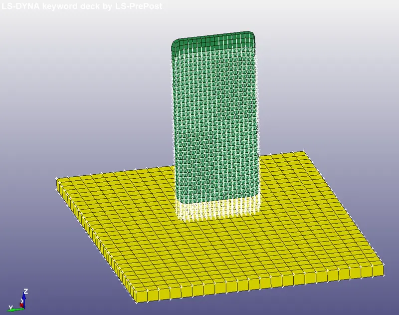
Now, for the initial velocity, Go to Create Entity >> Initial >> Velocity >> Select the part to be applied with initial velocity >> Enter the velocity along Z-direction (`Vundersetz`) and the value should be in negative to ensure the object falls to the floor.
The calculation of the Velocity is derived from the basic Displacement, velocity equations. Velocity V= `sqrt(2*a*d)`
Velocity V = `sqrt(2*9.81*10^-3*19.89)` where d is calculated by measuring the distance between node from the floor to the phone`
So the velocity is -0.626 mm/ms along Z-direction which is very less. So, we follow the standard velocity prescribed for the drop test which is 5.94mm/ms.
With the Boundary conditions applied, then we can proceed to apply the material properties for the parts. Here the materials choosen were Steel and Concrete. Since we are considering the rigid body as floor, we can use MAT_020 which is rigid material with the properties of concrete.
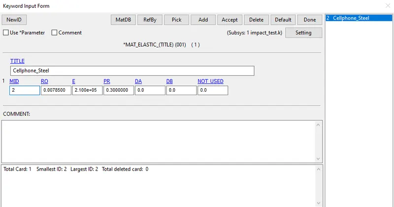
MAT_001 Elastic material can be used with Steel properties for the Phone.
For the creation of material, go to Keyword Manager >> Material >> Select the required material and enter the appropriate parameters for both the steel and the rigid body concrete.
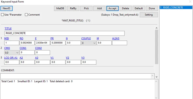
Once the material properties are created and then We need to provide the Contact interface between the two objects. Here, we need to provide Self Impact "Contact_Automatic_Single_Surface" for the phone since the phone can get collapsed and touches itself when dropped.
Then for the interface between Floor and the Phone, Provide "Contact_Automatic_Surface_to_Surface"
Here, for the selection of nodes, we should create Segment Set so that we can provide slave and master segment set ID respectively.
In the Self Impact we don't need to give any master ID since slave and master were same in that case. For the other interface the slave is given as the object on study which is phone and the Master is the Rigid floor.
Go to Keyword manager >> All >> Contact >> Select the respective contact type >> Enter the slave and master details >> Accept and done.
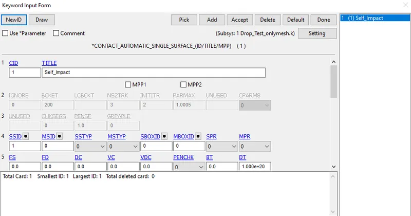
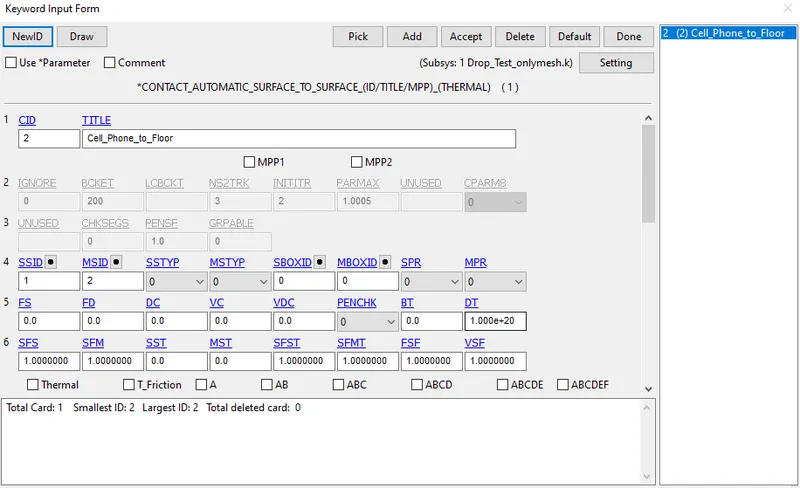
Now, all the contacts,materials, boundaries were created. The respective property and the Section ID should be updated in the Part so as to assign them to the respective parts.
Then, we should provide the Control cards. Go to Keyword manager >> All >> Control >> Termination >> Enter the DT (Time for the simulation to run)
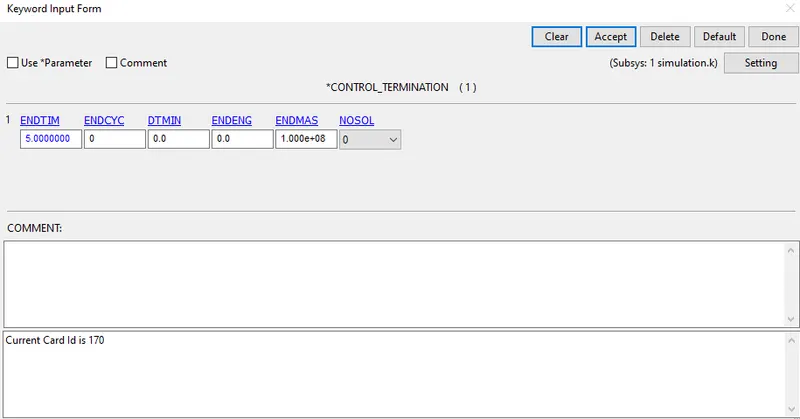
Now, The Outputs should be requested. The Output requested were Database : D3PLOT & ASCII files : GLSTAT, MATSUM, RCFORC. Those should also be provided with the DT time (0.1) for the outputs to be captured after each prescribed time.
Now, we can run the simulation. Save the Keyword file and open the same in the LS-RUN. Set the NCPU as 4 and then proceed to Run.
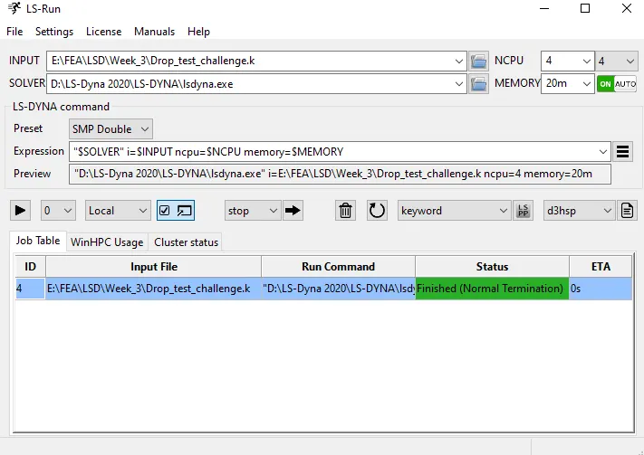
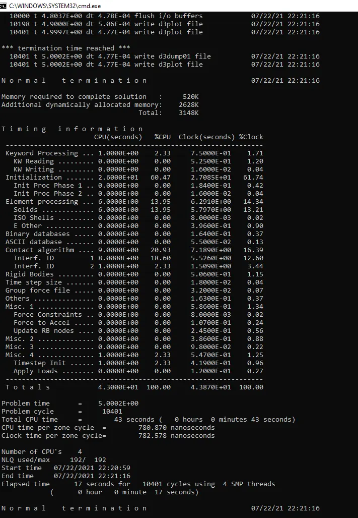
Once it is completed, then we can open the Binary Plot in the LS-Prepost to view the results. Open LS-Prepost >> File >> Open >> Binary Plot >> Select the D3PLOT and Open.
Let's see the results. The Resulting simulation is seen by opening the D3Plot in the LS-Prepost. Here is the Simulation of the Drop test.
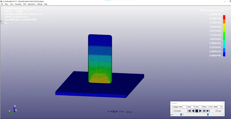
From the simulation It is seen that the contact between phone and the floor happens at 3.39ms and the von misses stress at the contact time is around 262Mpa.
Now, We can see the ASCII files. Here are the result plots of Global variables, Contact forces etc.
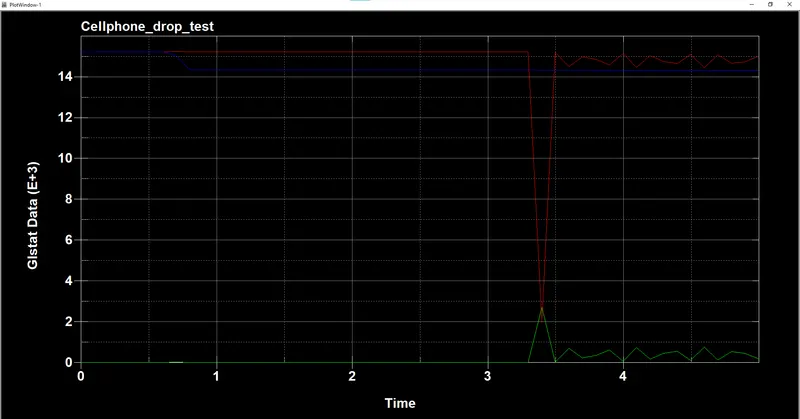
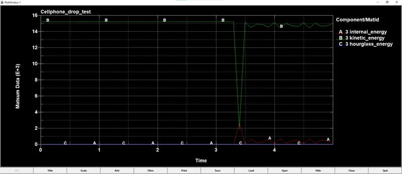
We can see that at the time of contact the Internal energy has increased. There would be some losses in the energy due to sliding contact and hourglass however at the end the total energy is conserved.
Results from the MATSUM plots:
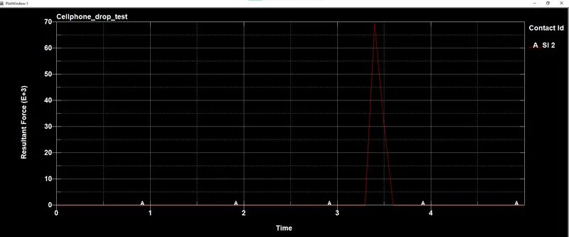
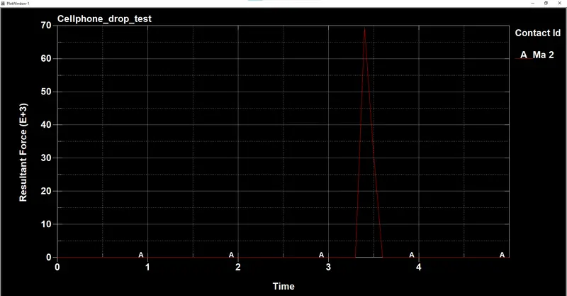
Results from the RCFORC plots:
RESULTS:
Thus, the drop test of the phone on the floor has been successfully simulated. The results might not be as exact as the real test which is due to the fact that there were not enough information about the model. This exercise gave us an understanding and experience about GUI of LS-DYNA and how to setup a simulation and post process the results.