Week 3 Challenge : CFD meshing on Turbocharger
Aim:
For the given model, check for the geometrical errors to make appropriate volumes. Create and assign PIDs.
Perform surface mesh with the given target lengths as per PIDs
- Blade stage-1 = 1 mm
- Blade stage-2 = 1 mm
- Impeller = 2 mm
- Shaft rotor = 1 mm
- Turbo casing = 5 mm
- Compressor casing = 5 mm
- Inlet casing cover = 5 mm
Perform Volumetric mesh for the required volumes as shown in the videos and write a detailed report on your surface meshing & Volume meshing process.
Geometry cleanup/Topo tab:
Import the geometry from File -> Open and the select the file.
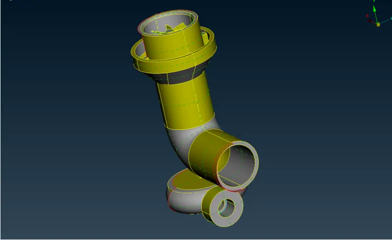
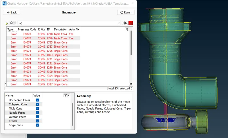
And the imported file is in the entity mode change it to PID mode.Turn on the cross hatches and the single ,double cons.The edges in ANSA are called cons and single cons are highlighted in red color, double in yellow color and triple in blue color. Double edge is shared by two surfaces and triple by three. Single cons are open edges and thy are not desired as every part of the geometry should be closed for CFD simulation.
Boolean operation/Tools in ANSA:

Or - It is used to isolate the selected surface.
And - It is used to retrieve the neighbouring/ connected surfaces.
Not - it is used to hide the selected surfaces.
INot - It is used to isolate the selected entities hiding all other surfaces/entities.It is similar to or , but we have to double click to isolate the entities.
All - It is used to retreive all the hidden surfaces.
Invert - It invert the current view,if a surface is hidden ,if we use invert the hidden entity will be visible leaving other entites hidden.
Lock - It locks the curren tview of the geometry, the hidden parts before lock cannot be retreived back.
Neighbour 1st level - It is similar to And operation which brings the adjacent cons to the selected surface.
Neighbour All - it is similar to the All option which retreives all the hidden entities.
Entity selection methods:
PID - It is use to select the whole entity.
PID region - It is used to select the specific region.
Macro area,MID ,VOL and PART are some common entity selection methods.
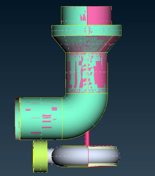
The model looks like this ,we have to delete the overlapped surfaces.
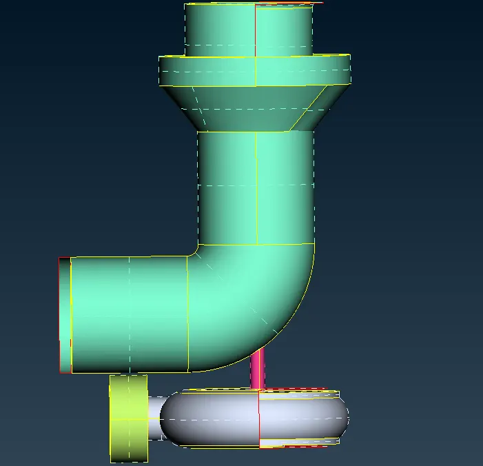
After deleting the overlapped surface the model looks like this.Use fill hole option to fill this deleted part.
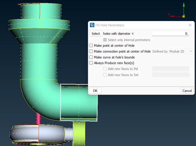
Fill hole option - It is used to fill the geometry of regular shape like rectangle square , circle etc.
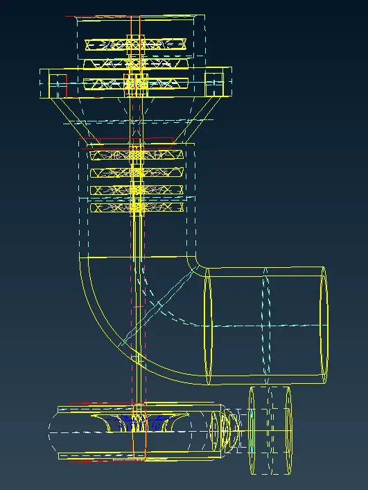
Use the checks option for the geometry and check if there is any error ,single cons present in the geometry and try to solve them.
Transform:
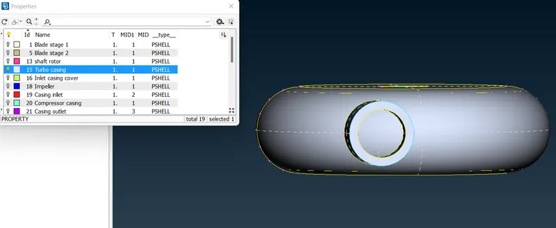
We can use transform option to fill this cavity on the turbo casing by copying the entity present on to the other side.Select mirror using 3 points and select the three points appropriately to mirror.
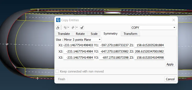
Then use Existing surface option to fill the hole.Then join the entity using the join option under mesh Tab.
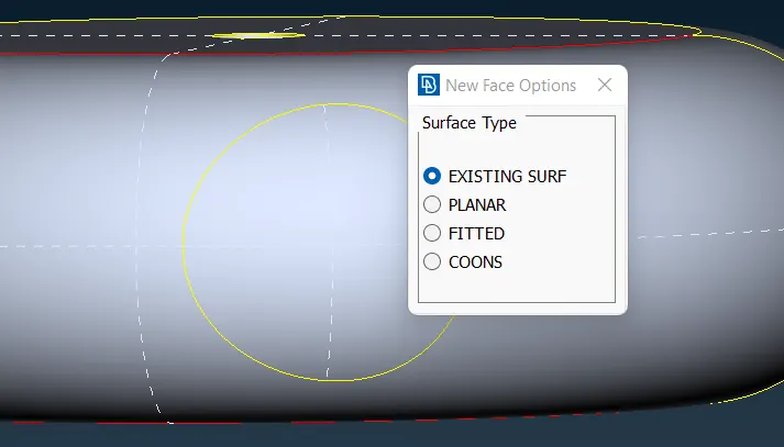
We can use the new option in the Face toolbar also.We have different methods to patch up the hole/cons.
There are four face options based on the surface type
1.Existing surface - It patches up the surface relative to a existing surface/neighbouring surface.
2.Planar - It is used to patch up the coincident surface or the holes present in the same plane.
3. Fitted - It is used patch up the regular known shapes like a circle,rectangle,square etc.
4.COONS - It got its name from a mathematician and it is used to patch irregular shapes or complex shapes.
Intersect:
Use the intersect option under faces to intersect these faces which are overlapped , select the first and second region and middle click to join the surfaces and delete the surfaces.
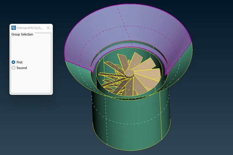
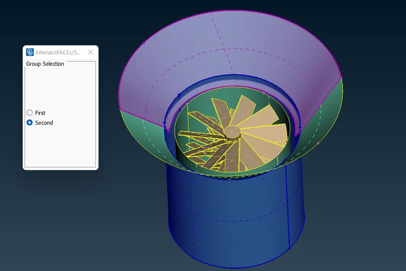
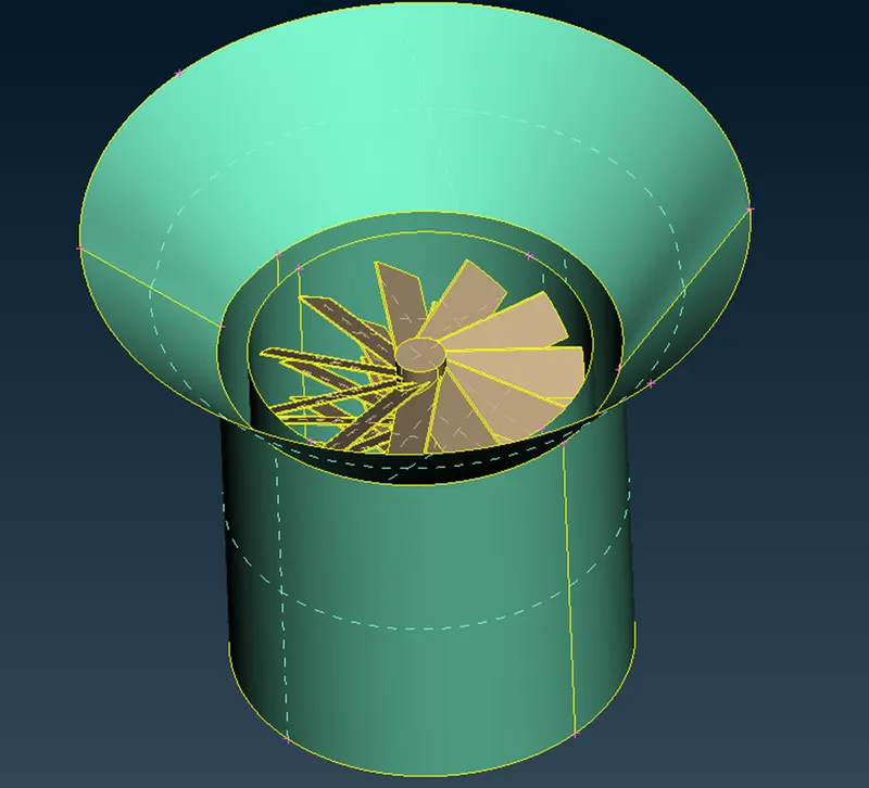
Now we have to delete all the overlapped surfaces on the shaft rotor.
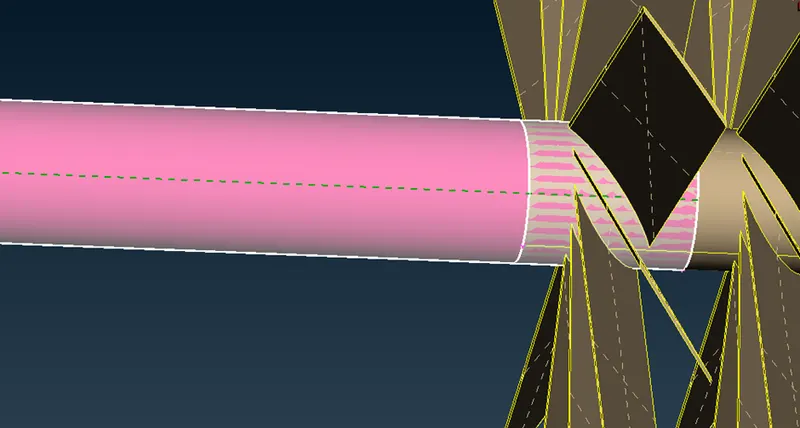
By projecting the entity on to the surface and using the topo option under we can make a triple con and delete the overlapped surface and use fine option to to make the edges fine.
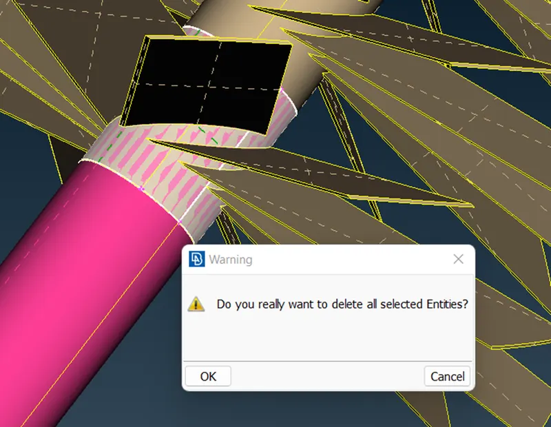
After solving all the single cons , deleting the overlapped surfaces and converting the shaft into single volume we can clearly see through the other side of the impeller.
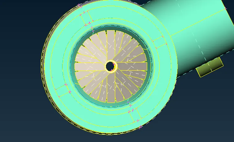
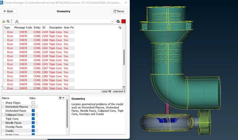
Here we can see all the single cons in the geometry have been deleted and only the necessary triple cons exist.
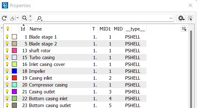
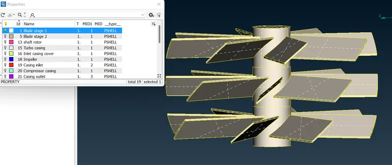
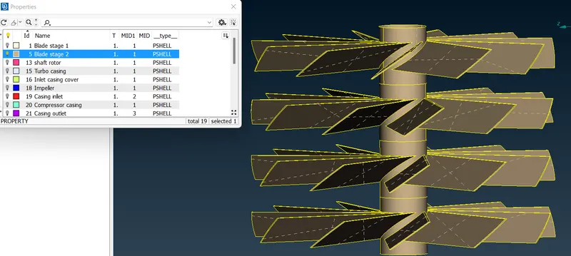
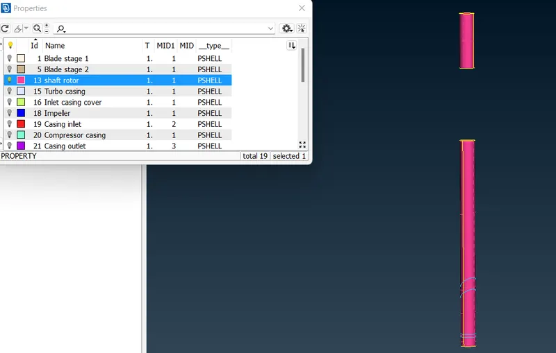

Meshing:
We have to give the mesh length parameters at four places.
1) Under perimeters we give length as 1mm under macros we give length as 5mm .We follow below steps for that ,
2) Go to mesh utility -> perimeters -> length -> now select perimeters and then-> click left mouse button and drag and select the entire model -> click middle mouse button -> Enter the element length as 5 mm -> Click middle mouse button.
3) Under mesh parameters we have to give at the target length as 5 mm and select element as tria and aslo give min and max length as 0.5 mm and 2 mm respectively and keep remaining to default.
4) In quality criteria we have to give min and max length as 3 mm and 7 mm respectively.
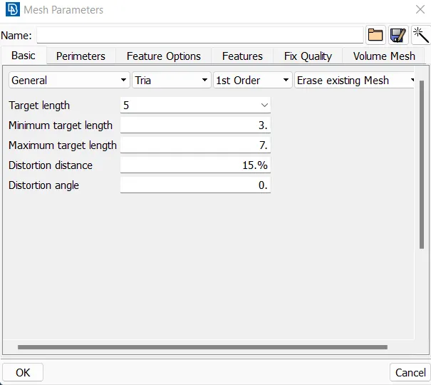
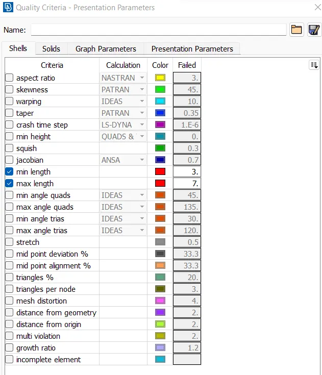
In length under perimeter tab specify the perimeter and macros target length.
Perimeter - It meshes on the perimeter for the given geometry.
Macros - It meshes the adjacent to cross section selection.
Use the respective target lengths for different entities
- Blade stage-1 = 1 mm
- Blade stage-2 = 1 mm
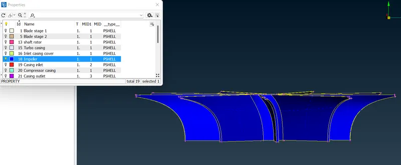
- Impeller = 2 mm
- Shaft rotor = 1 mm
- Turbo casing = 5 mm
- Compressor casing = 5 mm
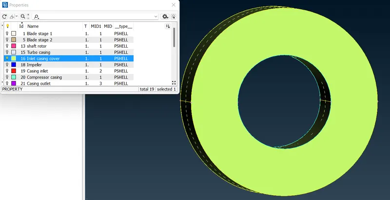
- Inlet casing cover = 5 mm
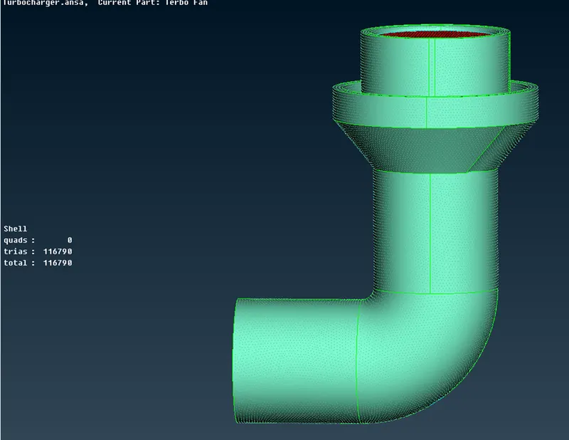
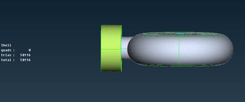
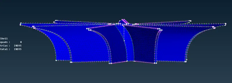
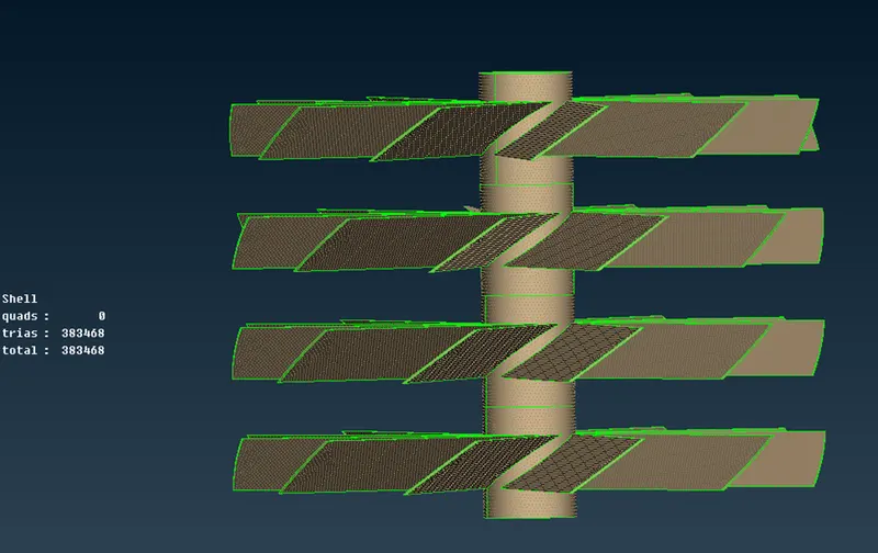
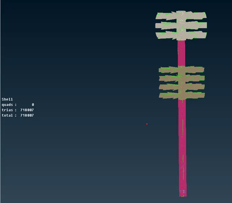
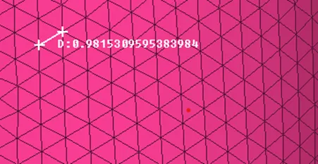
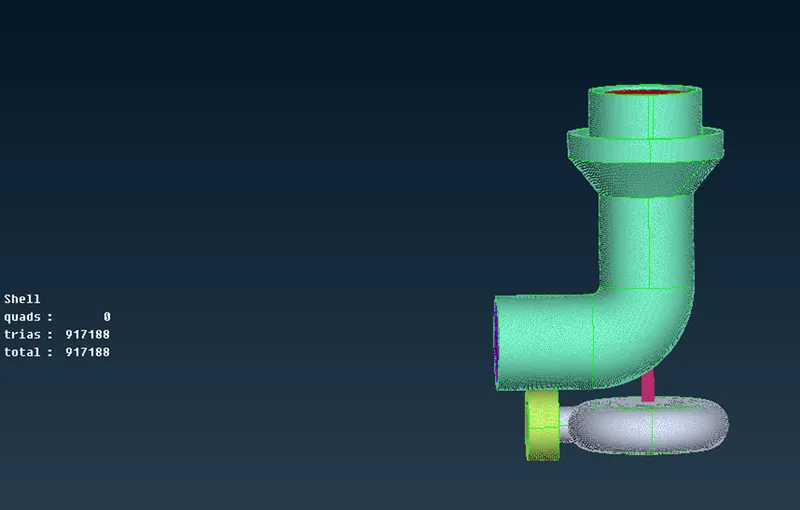
here we can seethe total mesh for the geometry which has no quad elements and all the surfaces are meshed.
Volume Meshing:
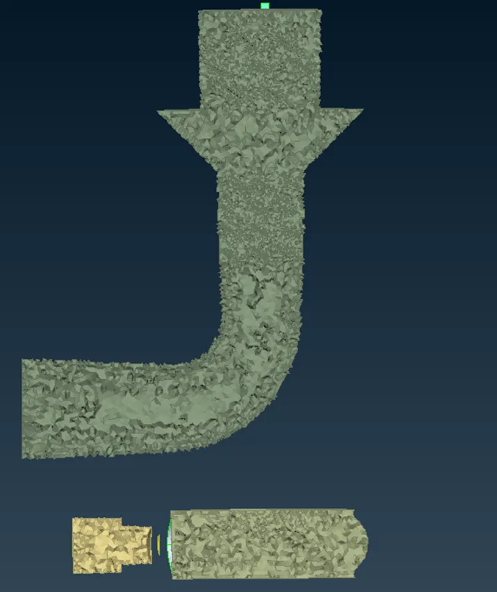
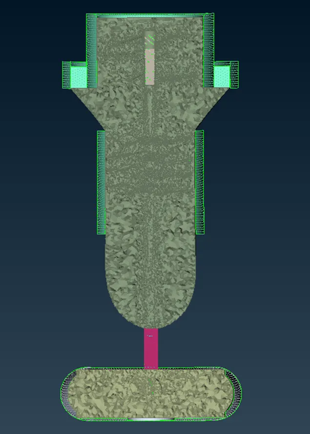
Lets move to the volume meshing tab where we have to create mesh for the volume of the geometry as we have just completed the surface mesh in the mesh.Volumetric meshing is important as it is responsible for the area under which the fluid moves around the geometry.
It is a very sensitive mesh so we should make sure that geometry does not have any errors in it.It takes a lot of time to mesh and more processing time.
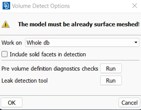
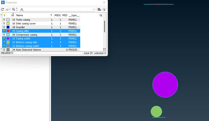
Under volumes tab we can see the define option under which we have to select the wholedb and automatically detected to find the list of automatically detected volumes to be meshed.
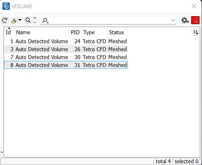
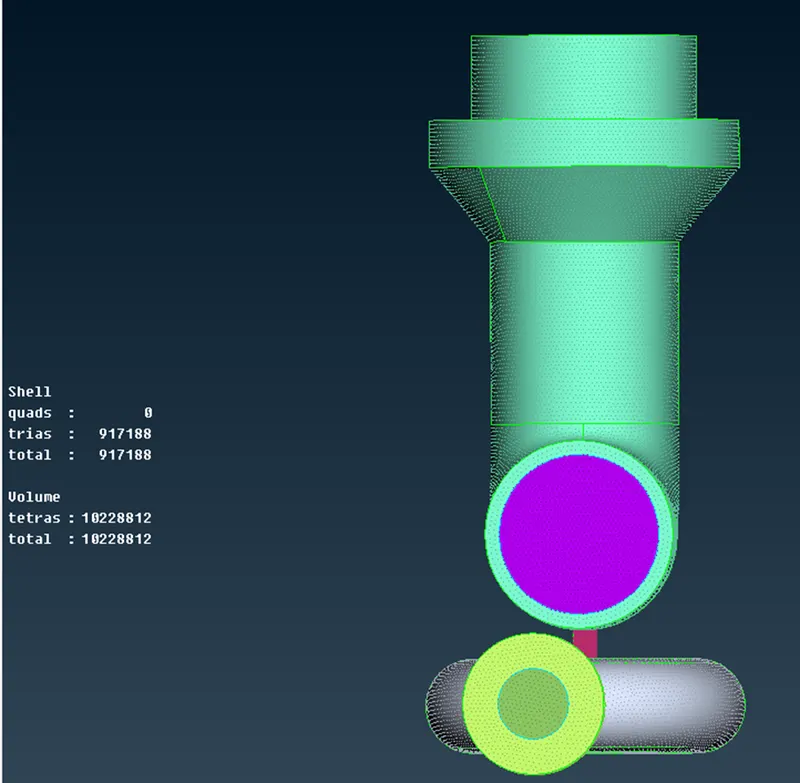
We have to delete the thickness of the geometry keeping only the volume of the geometry.
Conclusion:
Thus, the geometrical errors like single, double and triple con are checked and PIDs are assigned accordingly to the requirement and the surface is generated for with the given target lengths. Then volumetric meshing is performed for the volumed required successfully.