Week 3 Challenge : CFD meshing on Turbocharger
AIM`to`
For the given model, check for the geometrical errors to make appropriate volumes. Create and assign PIDs as shown in the video. Perform surface mesh with the given target lengths as per PIDs.
- Blade stage-1 = 1 mm
- Blade stage-2 = 1 mm
- Impeller = 2 mm
- Shaft rotor = 1 mm
- Turbo casing = 5 mm
- Compressor casing = 5 mm
- Inlet casing cover = 5 mm
Perform Volumetric mesh for the required volumes as shown in the videos.
Write a detailed report on your surface meshing & Volume meshing process.
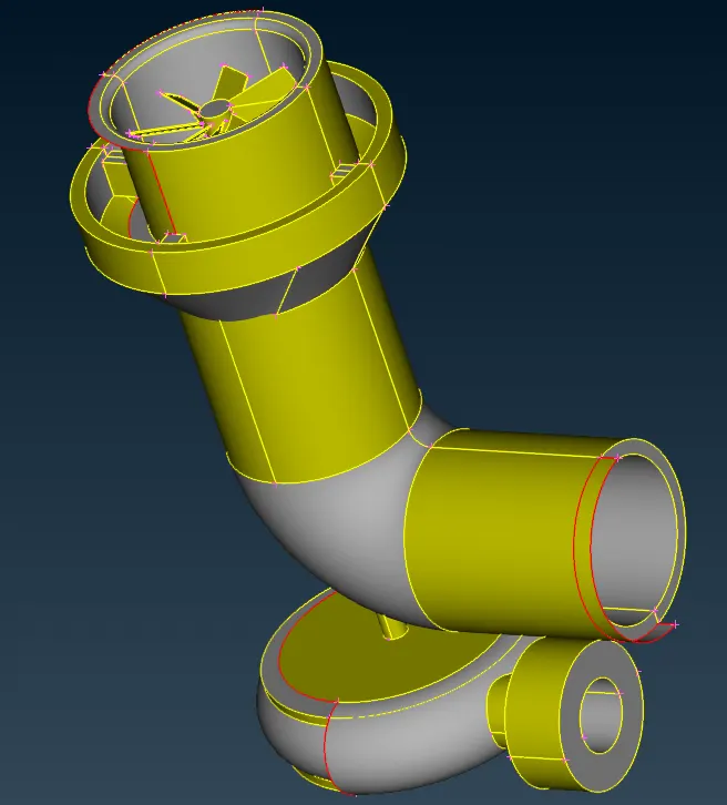
GEOMETRY OF THE TURBOCHARGER `to`
PROCEDURE `to`
The procedure involves GEOMETRY CLEANING, SURFACE MESHING & VOLUMETRIC MESHING.
GEOMETRY CLEANING `to` 
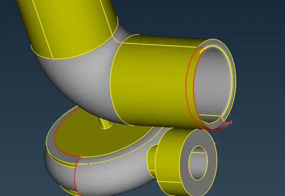
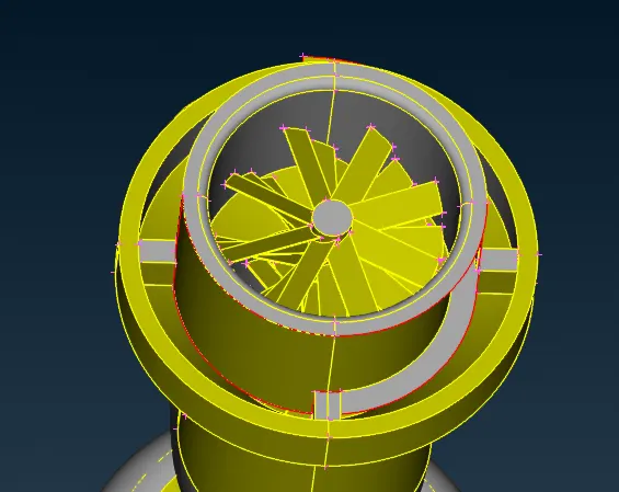
- The above shown geometry has many incomplete and penetrating entities which are shown as errors in the ANSA (via CHECKS MANAGER)

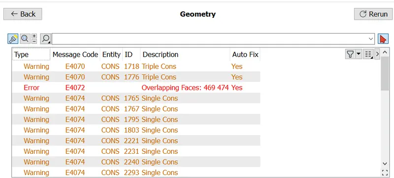
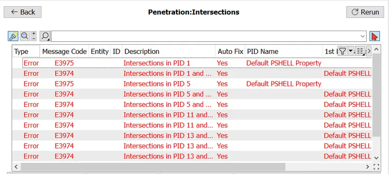
- There were geometrical as well as penetration errors. The geometrical errors were related to single, dowble and triple CONS. And the penetration errors where one entity penetrates into the other entity.
- The geomertrical errors were first one to get resolved.
- The errs caused by incompletely drawn surfaces were resolved by creating those surfaces using the command FACES > NEW. Here the surface type is asked and COON type was selected (as shown below)
. `to`
`to` 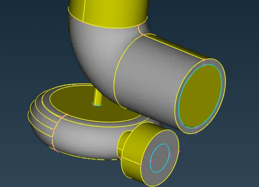
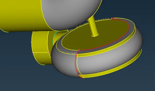
- Some errors required additional hotpoint creations using HOT POINTS > PARAMETRIC. The distance in percentage wise is given as 50%(as shown in figuree below).
 `to`
`to` 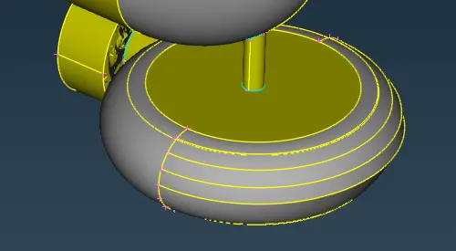
- the errors with complex curves were resolved by drawing additional curves and using the command HOT POINTS > INTERSECT(as shown below).
 `to`
`to` 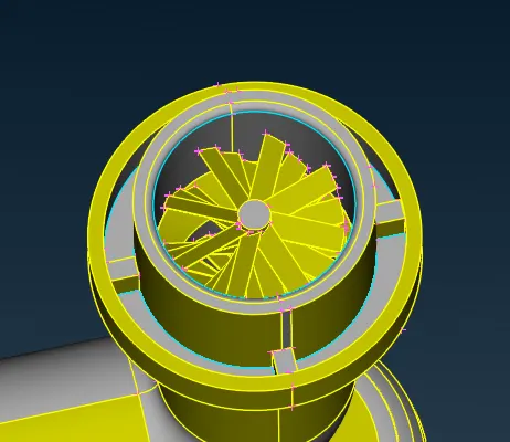
- water tight geometries are needed for the CFD meshing, therefore the inlet and outlets of compressor casing, turbo casing were closed by creating surfaces using FILL HOLE command.
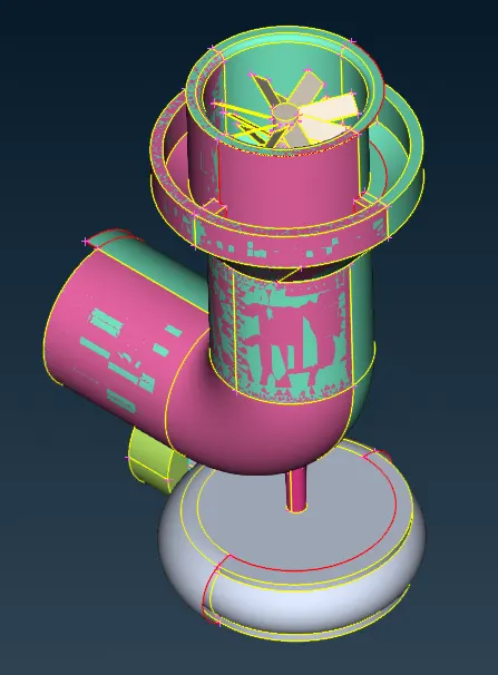
- There overlapping surfaces in the compressir casing which resemble like a glitches on the surfaces(as shown below).
 `to`
`to` 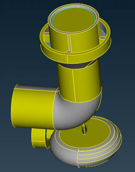
- Similarly, most of the single CONS formed were resolved into double CONS using TOPO command.
SURFACE MESHING `to` 
- For surface meshing, each components were renamed for better understanding.
|
Compressor casing with inlet and outlet
|
Turbo casing with inlet and outlet
|
Shaft rotor with two stages of blade
|
Impeller
|
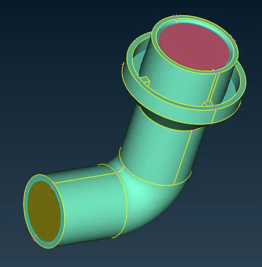
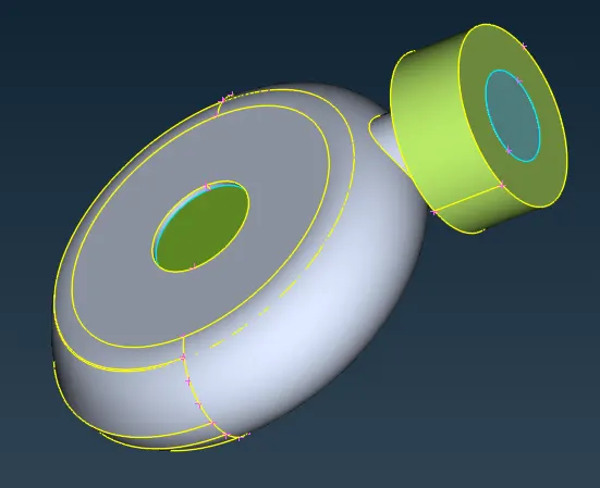
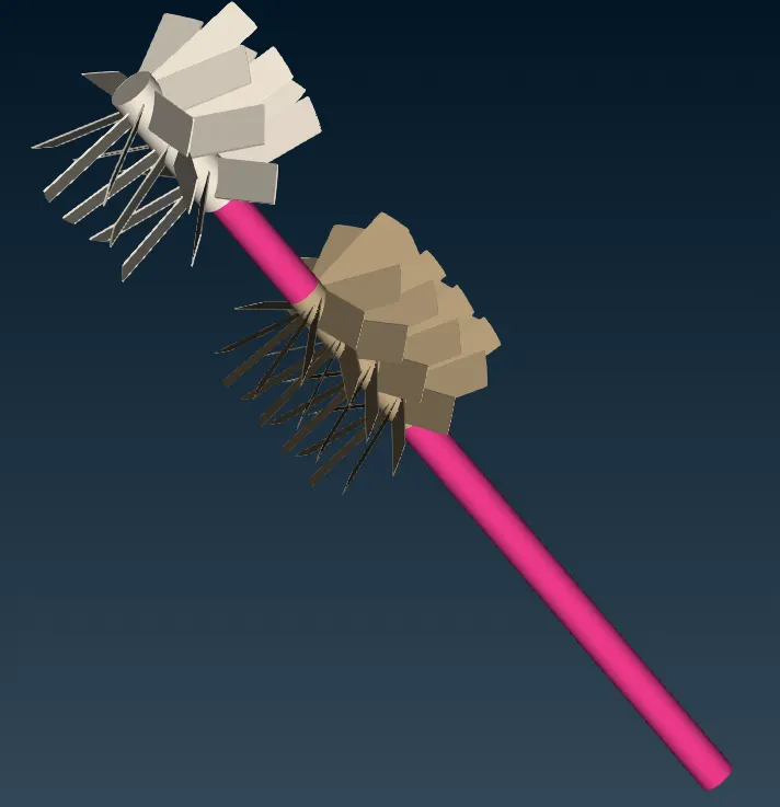
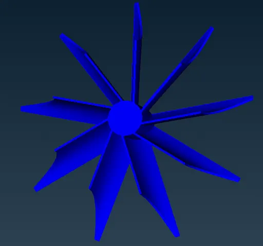
- Each of the above PID's were given specific mesh size. For wach component the target legth is equal to the mesh size. First the mesh size and target legths were asigned in the mesh parameters and mesh quality criteria. Followed by perimeters and macros are assigned. Atlast, mesh generation algorithm is specified. Here the alogorithm is spot meshing. Each components after surface meshing is as follows.
|
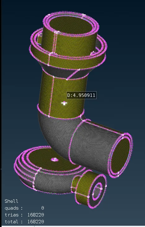
Compressor and turbo casing with inlet and outlet (5mm tria cell)
|
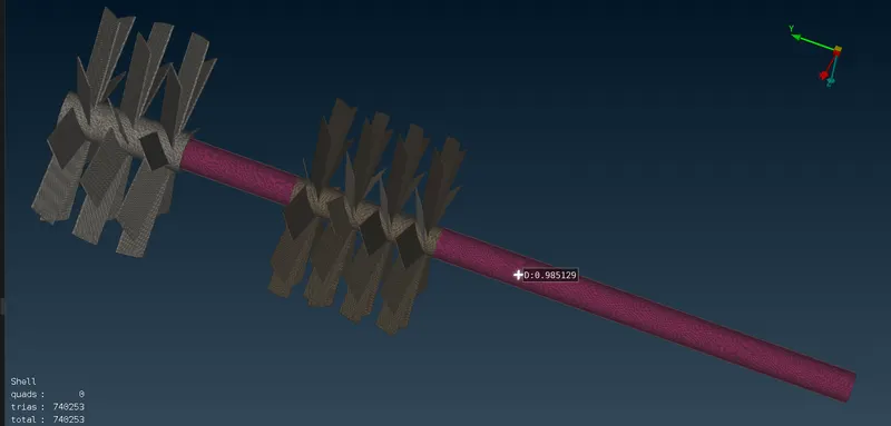
Shaft rotor with two stages of blade (1mm tria cell) |
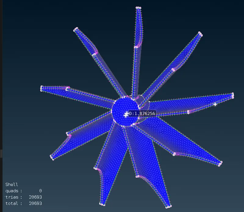
Impeller (2mm tria cell)
|
VOLUME MESHING `to` 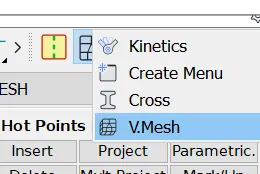
- Here we define the volume of entities which were surface meshed in the surface meshing operation (volumes > define >whole db).
- This will list out the volumes autiodetected by the ANSA. Note that these volumes are not meshed yet. They are just found by the software.
- Now these volumes are meshed using TETRA CFD type(as shown below).
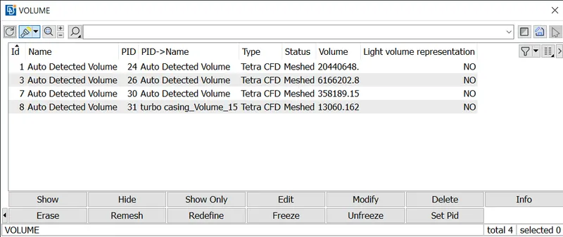
- Now the whole volumes are meshed by the ANSA software (as shown below).
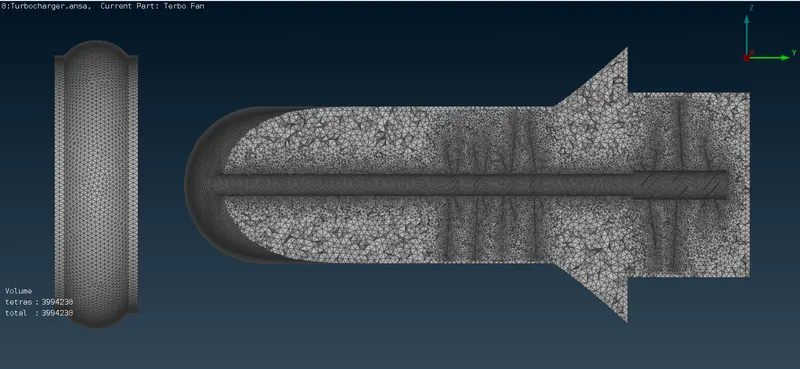
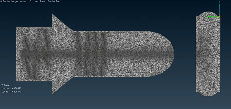
- Frome these voloume meshes (8 no:s), we have used only (4 no:s) of volume meshes which are only concerned to fluid flow, as per the CFD's requirement.
|
Backside cut section view
|
Frontal cut section view
|
RESULTS `to`
|
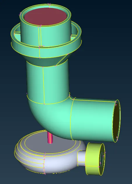
Geometry Cleaning `to` This is were the unwanted geometrical errors are resolved or cleaned for proper meshing.
|
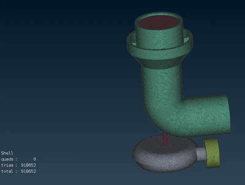
Surface Meshing `to` This is just the process of meshing the outer covering of each component. There is no volume or thickness involved. If a cut section is taken, it will be hollow from inside.
|
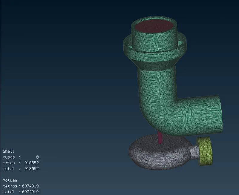
Volume meshing `to` This step is done only after the surface meshing is carried out. Note that the stats in the picture below shows the details of volume mesh. The no: of unmeshed cells is 0. There is noticeable difference between surface and volume meshing, but the stats shown are different.
|
CONCLUSION `to`
This work is for understanding the requirements of mesh type for an effective CFD problem. The whole problem depends on the domain of interest (i.e. geometry). If the geometry is complex, it is preffered to render it in sophisticated CAD softwares, because they are more convinient to create the geometry. On successfully importing these CAD models onto the CFD software can cause certain geometrical errors beccause of software issues or human error. so it is highly required to clean the geometry, preferrable defeaturing the domain with only the region of interest. Followed by proper meshing to obtain the reliable solutions. The volumetric mehsing carried out on this geometry requires the proper surface meshing, else, the meshing will not be proper.
Google drive `to`
https://drive.google.com/drive/folders/1euDkq-dHE5IGiCzDuUgeVV3XhbUCRyYG?usp=sharing