Week 3 Challenge : CFD meshing on Turbocharger
Aim : For the given model, check for the geometrical errors to make appropriate volumes. Create and assign PIDs for different components. Perform surface mesh with the given target lengths as per PIDs
Procedure for doing volumetric mesh for given component :
- The given model already assigned with pids by clicking different different component we doing topo clean
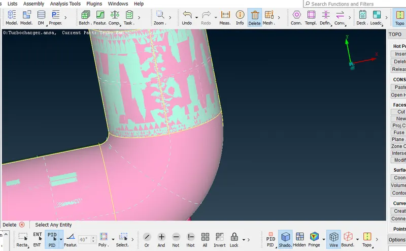
- In the component there is glich over there in the surface this glich because of the two overlapped surface this glich is solved by deleteing the unwanted surface by turn on the pid mode and selecting edge of the surface and delete
- In topo clean second thing we finding the cracks by view the single con Then we patching the cracks by cons option which there option in new option present in right of the screen that is in face section
- to patch the crack we selecting the cons option and turn on the loop option which is there bottom of toolbar then selecting cons we are patching the all cracks
- but in turbo there is one end is opend to cover that above loop con option not used because it not gives exact needed surface
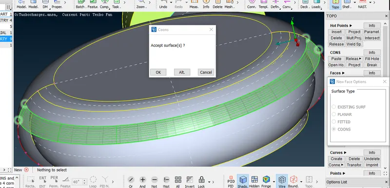
- so for that we creating hot points in different different position using parametric option which is present in the hot points option in right of the screen this hotpoints is shown in the image below then turning on the entity mode and selecting the cons we creating the surface so by this step by step we cover the opened end surafce
- similarly in compressor inlet to cover the surface we projecting the hot points by clicking one end of con to perpendicular to other end of con by using project option which is there in hot point option in right of the screen this method is used because to cover good surface this method is shown in the image below
- similarly for different different component there is glich present and single cons present like in the inner part there in shafts blade component glich present, single con present ,triple con present by looking over that using above method which is all metioned we doing topoclean up
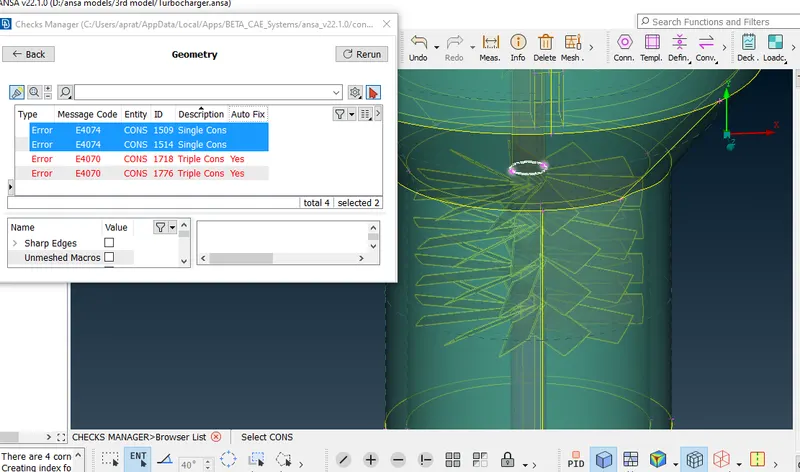
- note that there is two surface is attached but single con it showing in screen so for this selecting topo option which is there present in right of the screen and selecting the single cons we doing topoclean up
- similarly where ever there is triple con by deleting unwanted surface we doing topo clean
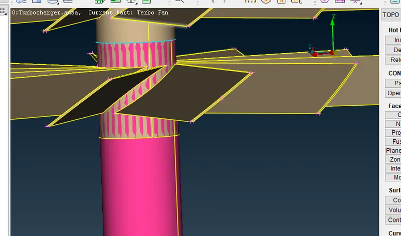
- And also in blade shaft component in bottom small portion of pink and brown shaft overlapped so when to avoid glich if we delete one surface then the entire one shaft going to deleting but we don't want to delete entire shaft for that we want to delete pink surface in that small portion which is overlapped for this we projecting the cons in small portion which is shown in the image then we deleting the pink surface by clicking edge of the small portion of pink surface
- so by this we done with the topo cleaning then going to mesh the different different component with different different target length
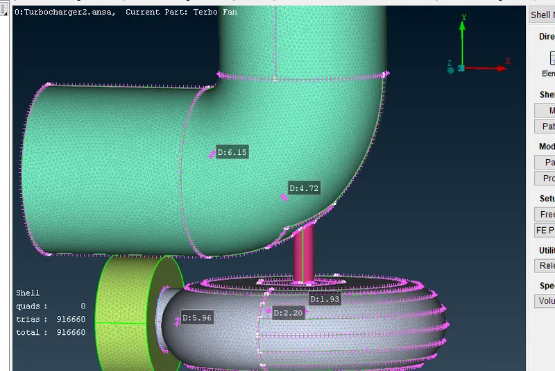
- so for turbo casing, compressor casing, inlet casing setting target length of 5mm to the perimeter, macron, in quality creteria giving min 3mm and max 7mm and in mesh parameter giving average 5mm min 3mm max 7mm and setting element type tria we meshing these component
- similarly for blade stage1, blade stage2 and shaft giving target length of 1mm we meshing these component
- and also same in impeller we giving target length of 2mm we meshing these component
- so by these we completed 2d mesh now go with volumetric mesh
- In volumetric mesh first we defining the all volume using define option shown in the right of the screen so there we selecting what all volume we need we selecting that other we deleting that volumes
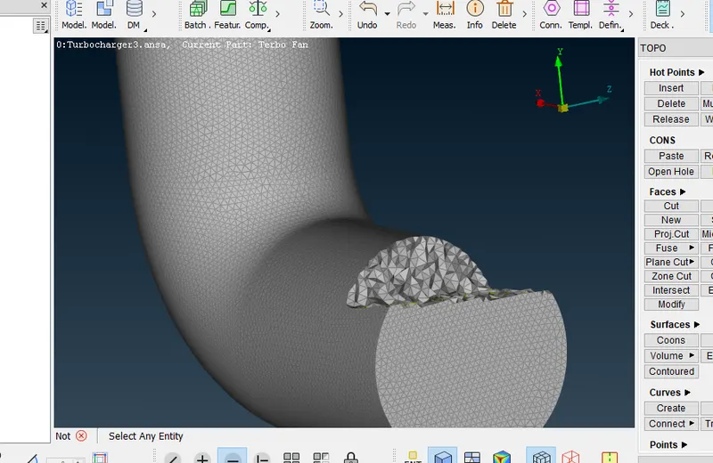
- usually we selecting the volume which fluid we analyzing in turbo charger that volume portion we selecting which shown in the image then by show only that volume we meshing the tetra cfd mesh which is there option in the right of the screen. By this we completed the challenge
learning outcomes:
- first step we are doing topoclean which we cleaning single con, unwanted triple con , cleaning overlapped surface, and colsing the sufrace which need for cfd analyse
- after topo clean giving target length and element type we are the component
- after meshing we are doing volmetric mesh of the selected volume
Result are attached below :
1.Image shows pink overlapped surface
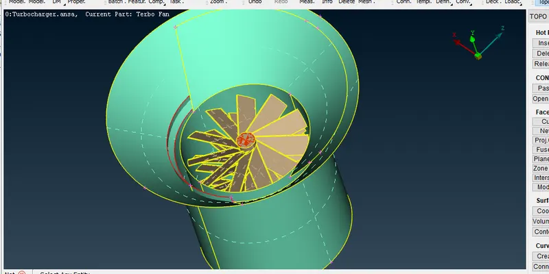
2.view of Two surface intersected :
3.View of Geometric checks shows single con and triple con:
4.View that For to cover the surface we creating multiple hot point and selecting con creating surface in the step by step wise:
5.View of Projecting the hot points over one con to perpendicular to opposite con:
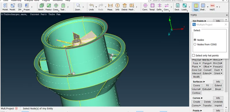
6.View of between two stafts small portion is overlapped this is solved by inserting cons on the suface of shaft:
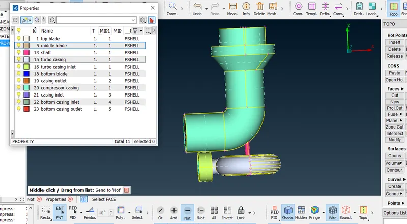
7.View of assigned the pid of different different component:
8.View of the surface mesh:
9.View of that which volume is meshed with volumetric mesh:
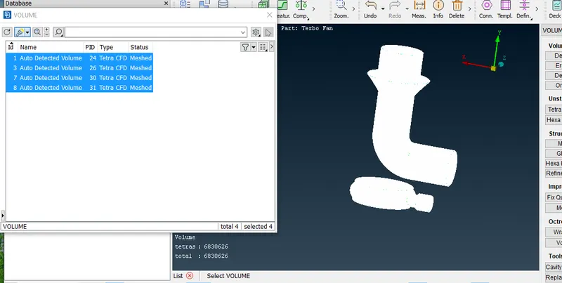
10.View of final model which is meshed with tetra cfd:
link of the model :https://drive.google.com/file/d/1GXQGMFnybB_Zon9pCBULYIJRtE788Tpk/view?usp=sharing (zipped file)
conclusion :
Finally volumetric mesh of the given component is completed successfully by doing above methods