Week 3 Challenge : CFD meshing on Turbocharger
Aim: To check the geometry for errors and create surface mesh and volumetric mesh for the given regions.
Obective of the project:
- To check the model for the errors.
- Fix the errors.
- Create and assign PID's for the geometry with given information.
- Perform a geometric check for the geometry validation.
- First perform the surface mesh.
- Then perform the volumetric mesh.
- The tools/command used are:
- Intersect.
- Fill hole.
- Mesh.
- V Mesh.
- New surface.
- TOPO.
- Hot Points.
- Delete Hot points.
- Tools.
- Resolution setting.
- Mesh.
- Perimeters.
- Length.
- Macros.
- Mesh generations.
- Spot Mesh.
- Measure.
- Shadow.
Content of the body:
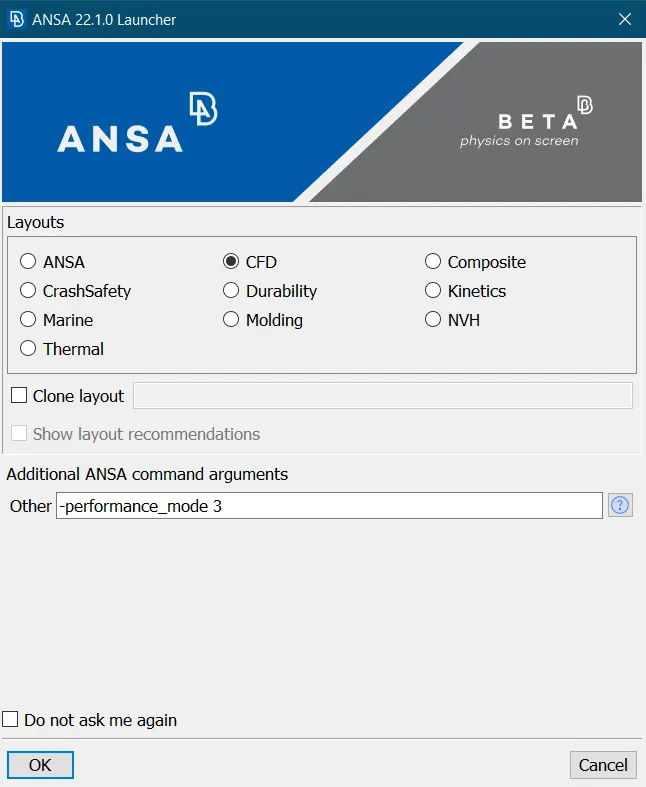
- Open the ANSA software in CFD mode with high performance category:
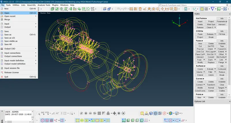
- Now import the file to be meshed:
- Now as we can see there are multiple errors in the geometry:
- Overlapping surfaces.
- Extra surfaces.
- Incomplete surfaces.
- Water Tight geometry.
- Single cons.
- Triple cons.
- Now correct the errors in the geometry.
- Overlapping surfaces:
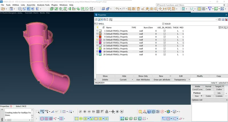
- Here as shown in the below figure there are overlapping surfaces, so to fix it delete the extra surfaces:
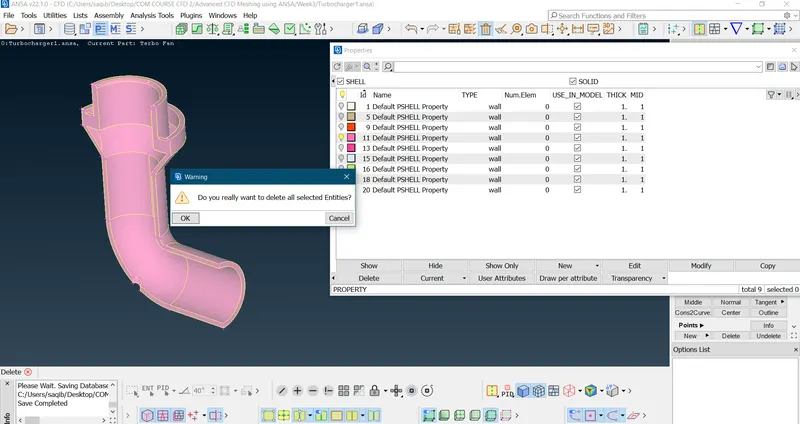
- Now hiding the surfaces find the hidden/overlapping surfaces and delete it:
- Here as shown in the below figure there are overlapping surfaces, so to fix it delete the extra surfaces:
- Extra surfaces:
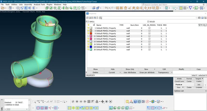
- There are many extra surface find them and delete them:
- There are many extra surface find them and delete them:
- Incomplete surfaces:
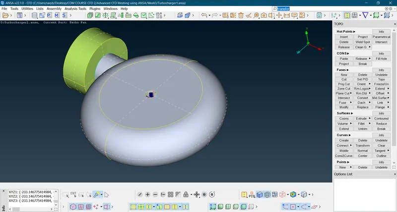
- In turbine region(outer casing):
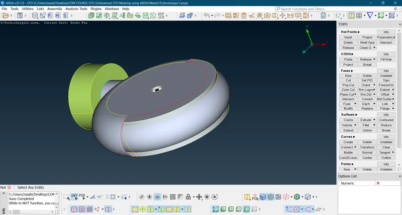
- As this is symmetric this can be used as an advantage to mirror the remaining part.
- Insert a hotpoint for reference.
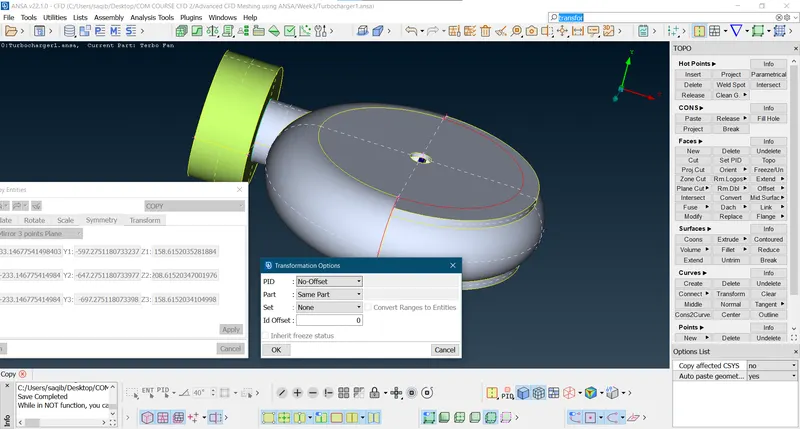
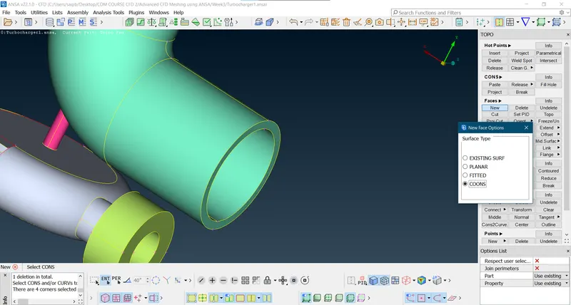
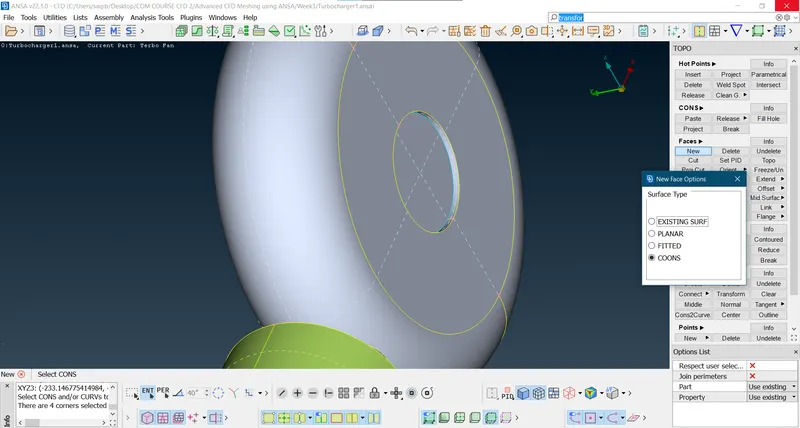
- Use topo to connect the surface coons.
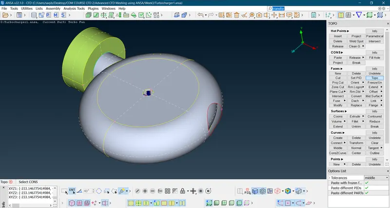
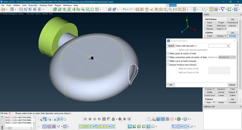
- By using the fill hole option fill the hole to get a surface and the final surface is shown below:
- At the top of the column:
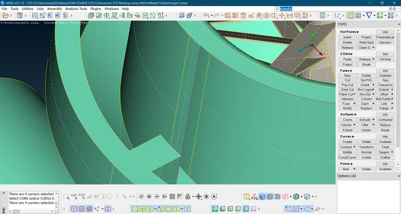
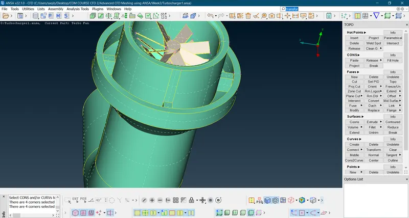
- Use new curves (create curve options) and create a new surface after the line and curve intersect as there was no other options of creating new surface for this part of the geometry.
- Delete the curves and create the new surfaces.
- Between the surface at the inlet of the compressor:
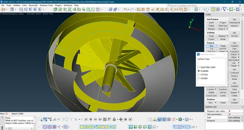
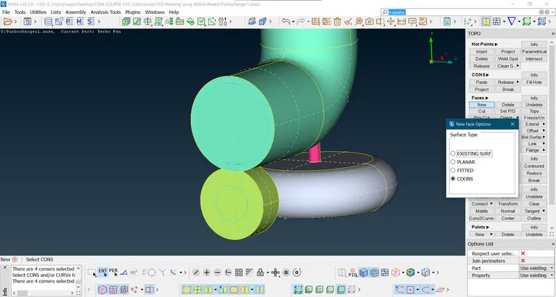
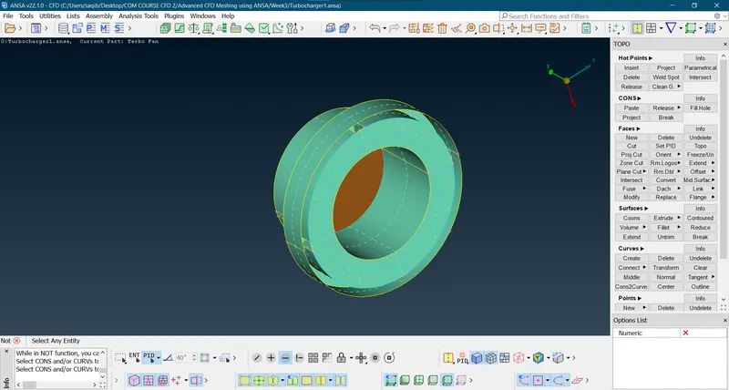
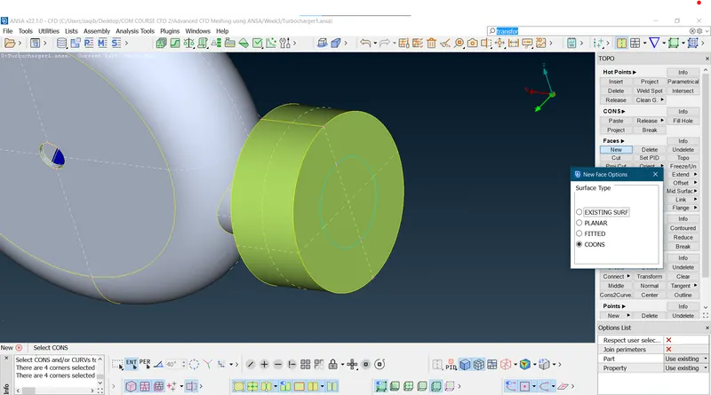
- Here there are open surfaces which needs to be closed in order to perform a volumetric mesh.
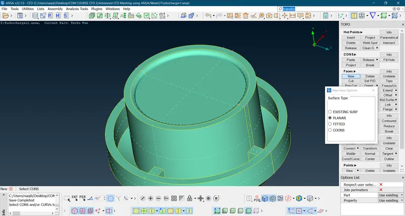
- Using the planar new surface command the surfaces are created.
- After finishing;
- In turbine region(outer casing):
- Water Tight geometry:
- For the Turbine:
- Compressor:
- Entrance of the compressor(planar):
- Exit of the compressor:
- For the Turbine:
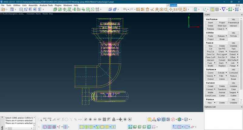
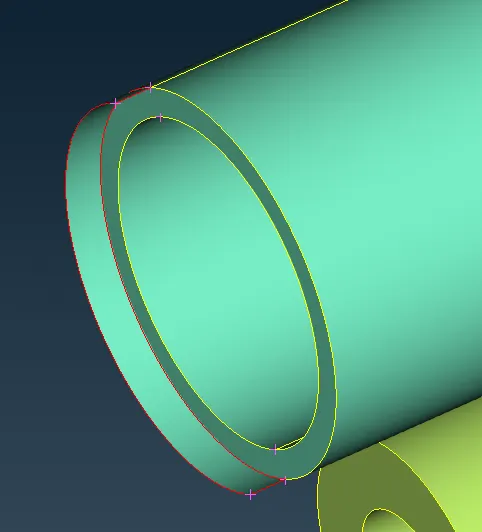
- Single coons:
- Now find the single cons hidden and fix them:
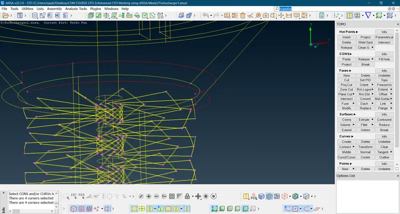
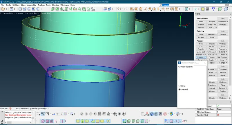
- Use the intersect option to fix it:
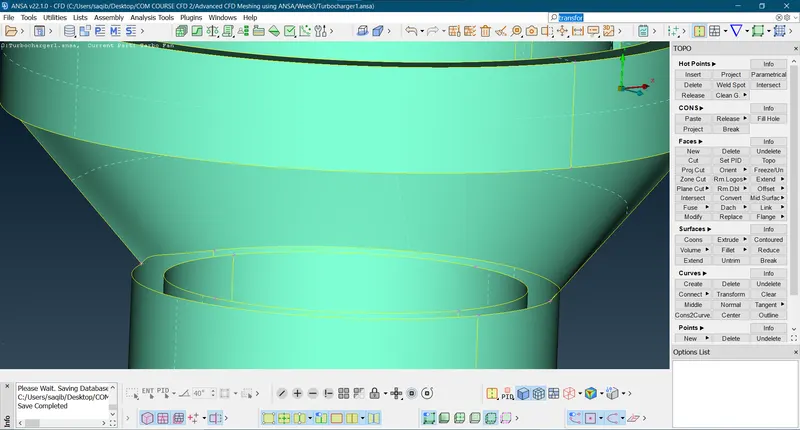
- Now find the single cons hidden and fix them:
- Triple cons:
- There are extra surfaces causing the triple cons, so deleting the cons for the better geometry configuration:
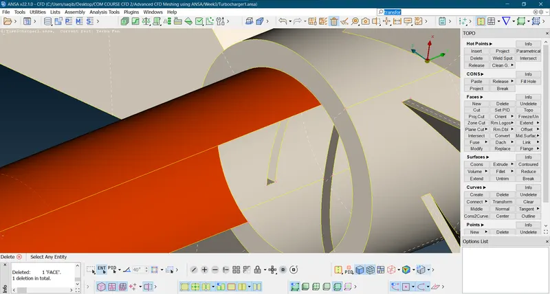
- Here project option is used to project the shaft cons to the upper surface as they are in touch with complete surface, then the triple cons caused are deleted.
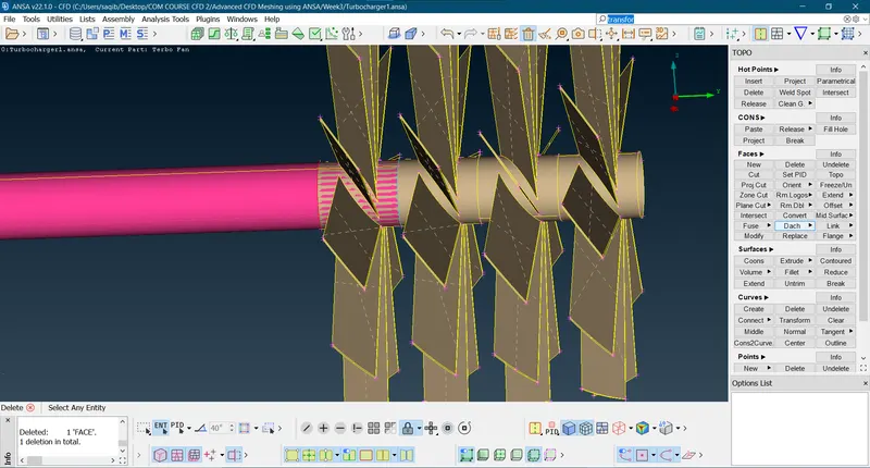
- Now to solve the overlapping issue first use the project and the delete the extra overlapping surfaces.
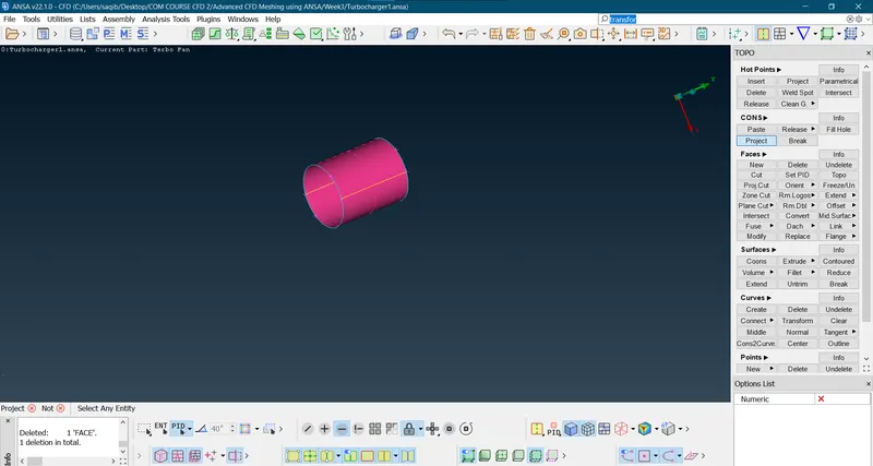
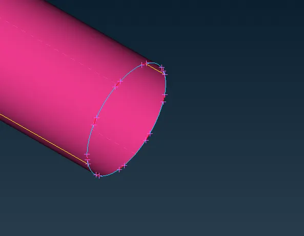
- After finishing:
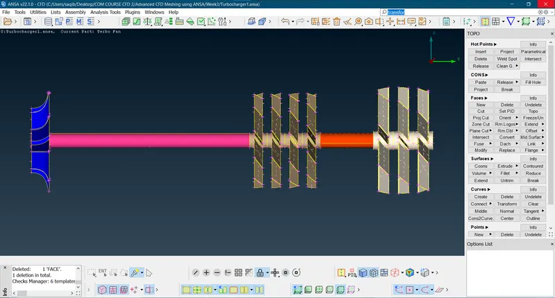
- There are extra surfaces causing the triple cons, so deleting the cons for the better geometry configuration:
- Overlapping surfaces:
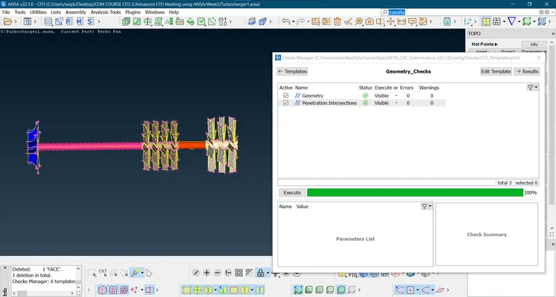
- After this running the ‘Geometry check’:
- After running the test for the entire geometry;
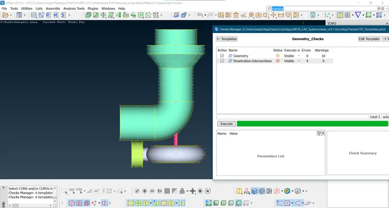
- All the geometry warnings are for the triple cons which are justified by the watertight geometry (10 triple cons).
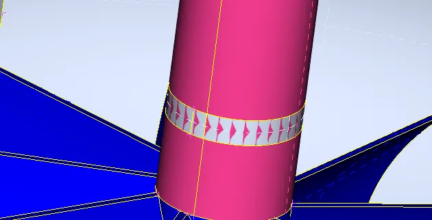
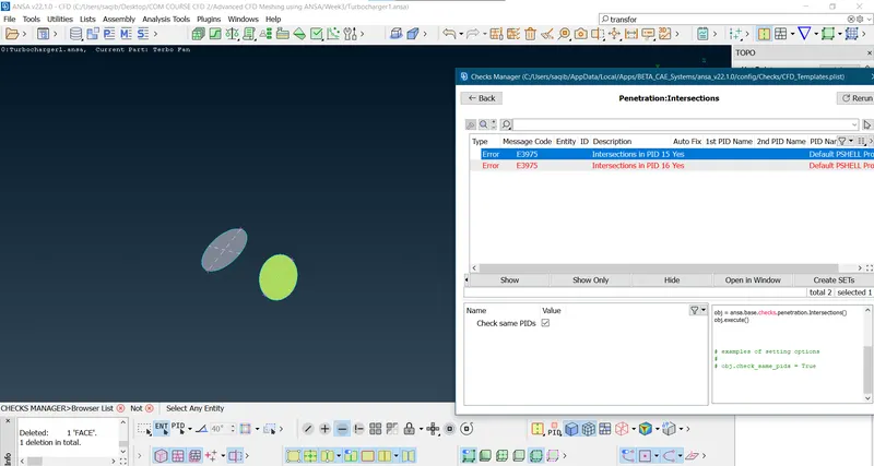
- Now Penetration Intersection errors need to fixed:
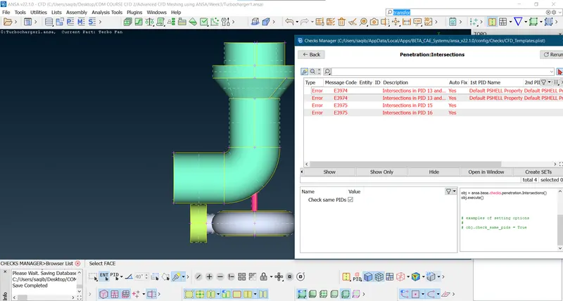
- The above shown figure shows the warnings of the triple cons which are justifiable as water tight geometry.
- Creating the PID for the geometry:
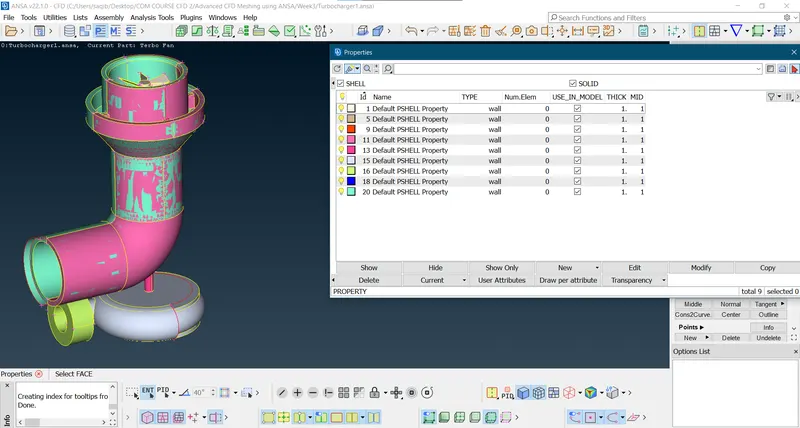
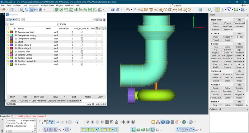
- Create the PID for each component of the geometry.
- Check of any unused PID using compress from the tool bar:
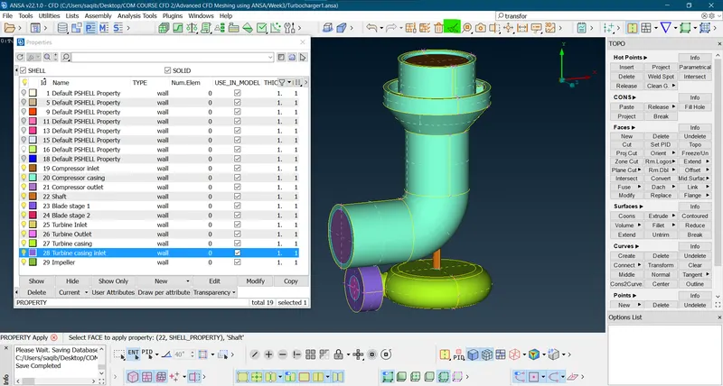
- After the compression the PID are:
- Meshing:
- Here the surfaces are meshed to the prescried properties.
- Blade stage-2 = 1 mm
- Impeller = 2 mm
- Shaft rotor = 1 mm
- Turbo casing = 5 mm
- Compressor casing = 5 mm
- Inlet casing cover = 5 mm
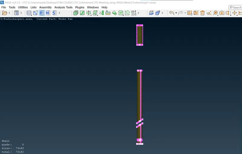
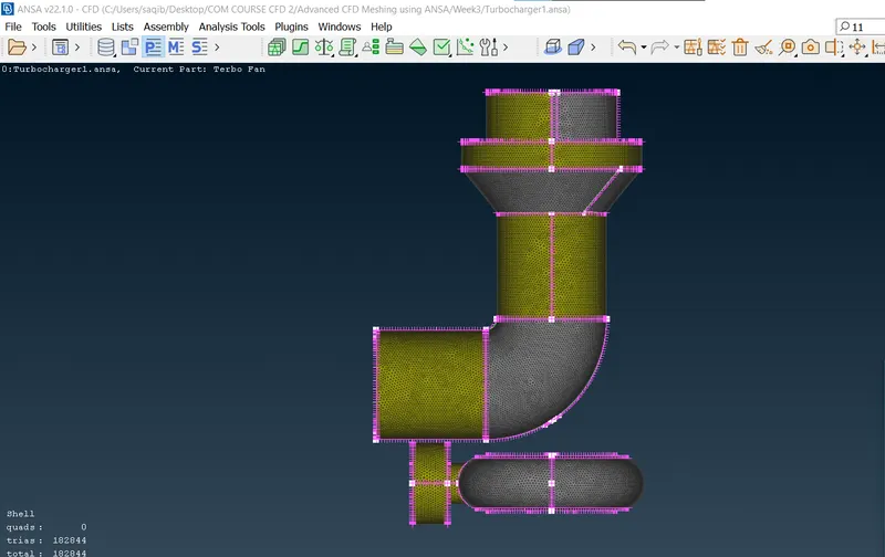
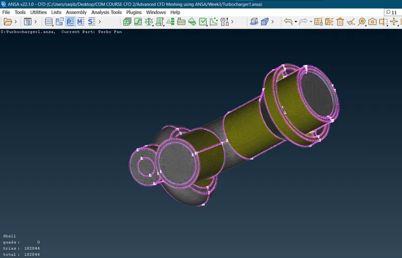
- After meshing the surfaces:
- As there are no unmeshed components we can proceed the volumetric mesh:
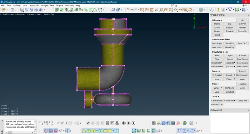
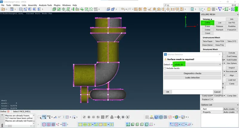
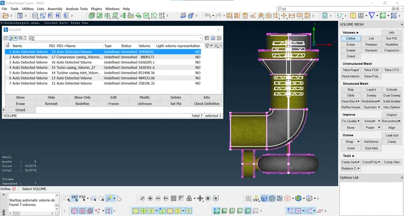
- By using the 'Define' let the whole data base be defined.
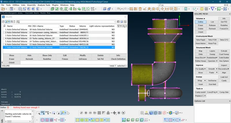
- Seven volumes are detected.
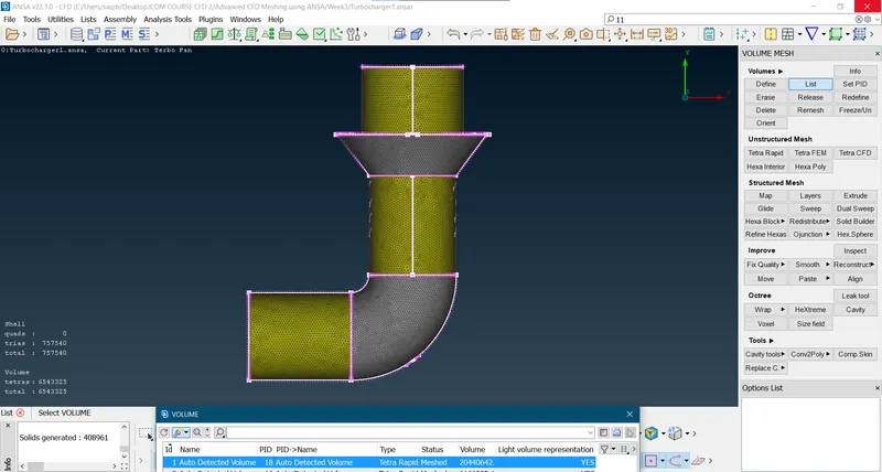
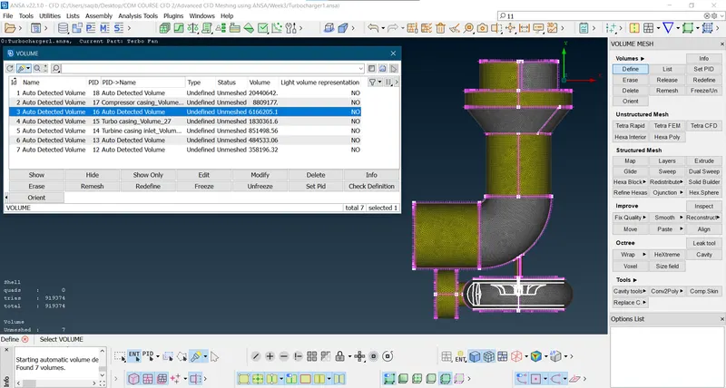
- Fluid volume of the compressor casing:
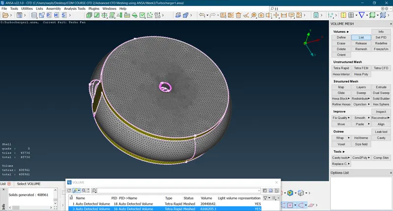
- Fluid volume of the turbo casing:
- Now select the volumes which are to be meshed i.e. fluid volume of the compressor casing and fluid volume of the turbo casing and delete the all other volumes for the clear operation.
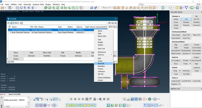
- The mesh is generated by using the tetra rapid.
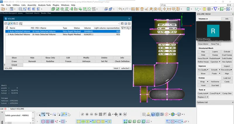
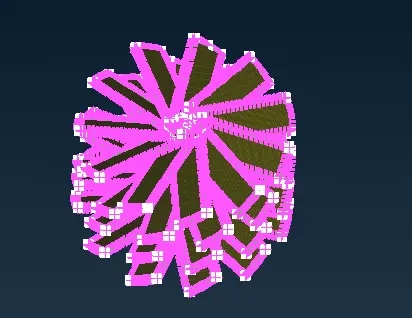
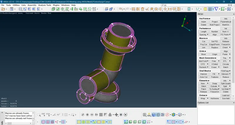
- Meshed fluid volume of the compressor casing fluid region(tetra rapid):
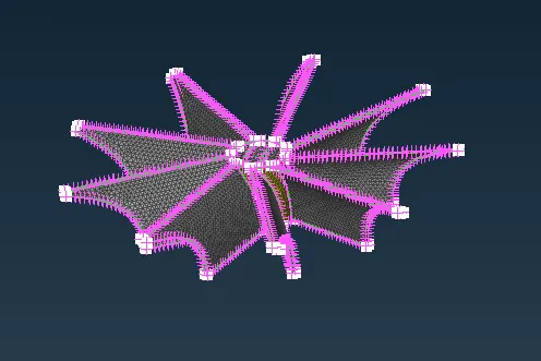
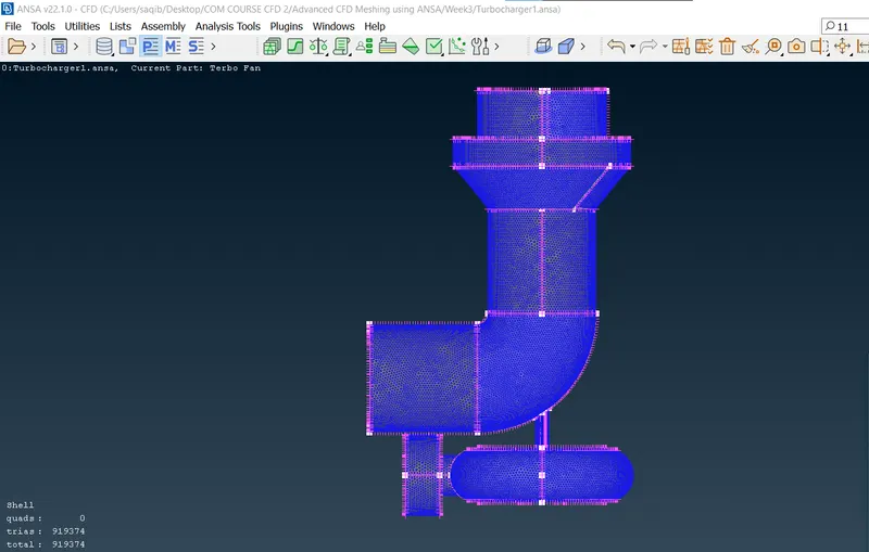
- Meshed fluid volume of the turbo casing(tetra rapid):
Results:
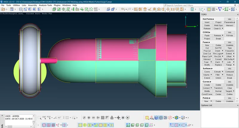
- The geometry before the meshing procedure:
- The geometry after the cleaning and meshing:
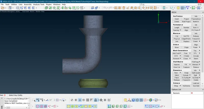
- Both fluid volumes after meshing:
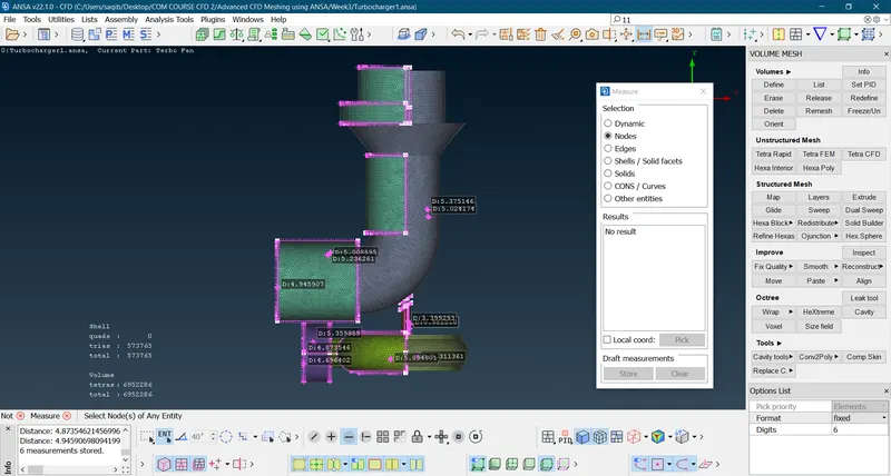
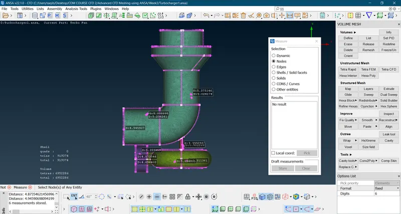
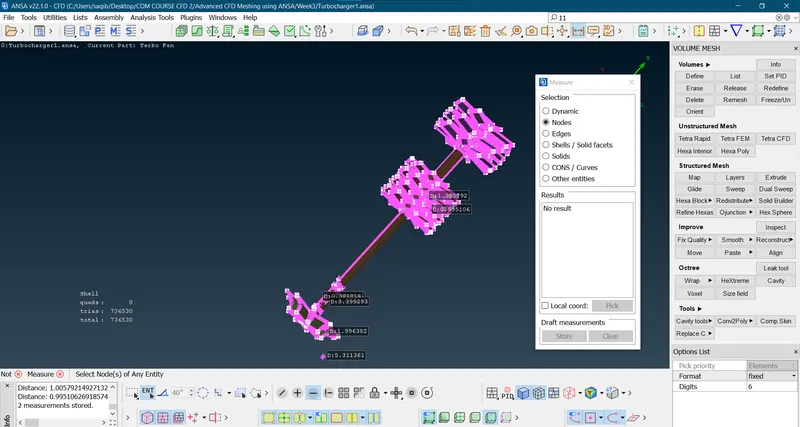
- The elements/nodal length of the mesh components are measured and are in accordance.
Learning Outcomes:
- Here geometry clean up, Intersect, PID creations, Surface meshing and volume meshing are understood and executed as the results of this challenge.
Link to the geometry:
https://drive.google.com/file/d/1wTlQmHMmLeXQsyaotRw4iJtM-TOUQo7s/view?usp=sharing
Conclusions:
- The geometry is successfully inspected, cleaned and meshed for the surface and volume according to the specifications provided.
- The procedure of the process followed are explained in detail with respective illustrated images.